
Information Update - Processor Installation
Page 3
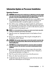
.... 8 Gently lift the heat sink off the system, including any of the components inside the system. Before you begin this procedure, review the safety instructions that you intend to remove the processor. WARNING: The heat sink and processor are authorized to remove the system cover ...Prior to upgrading your Hardware Owner's Manual for a system-specific illustration. See your system, download the latest system BIOS version from support.dell.com and follow the instructions included in the compressed download file to install the update on components in the interior of the heat sink....
.... 8 Gently lift the heat sink off the system, including any of the components inside the system. Before you begin this procedure, review the safety instructions that you intend to remove the processor. WARNING: The heat sink and processor are authorized to remove the system cover ...Prior to upgrading your Hardware Owner's Manual for a system-specific illustration. See your system, download the latest system BIOS version from support.dell.com and follow the instructions included in the compressed download file to install the update on components in the interior of the heat sink....
Information Update - Processor Installation
Page 6
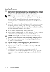
... the system cover and access any of the processor. NOTE: In a single-processor configuration, the CPU1 socket must be used. 1 If you begin this procedure, review the safety instructions that came with the system. Place your fingers on the ZIF socket. When the processor is shown as a triangle on the top...
... the system cover and access any of the processor. NOTE: In a single-processor configuration, the CPU1 socket must be used. 1 If you begin this procedure, review the safety instructions that came with the system. Place your fingers on the ZIF socket. When the processor is shown as a triangle on the top...
Getting Started Guide
Page 5
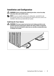
... came with your system. NOTE: If you are using the optional rack configuration, assemble the rails and install the system in the rack following procedure, review the safety instructions that can be extended outward to the system. Getting Started With Your System 3 Installation and Configuration WARNING: Before performing the following the...
... came with your system. NOTE: If you are using the optional rack configuration, assemble the rails and install the system in the rack following procedure, review the safety instructions that can be extended outward to the system. Getting Started With Your System 3 Installation and Configuration WARNING: Before performing the following the...
Hardware Owner's Manual
Page 30
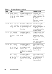
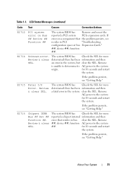
.... The system BIOS has reported an I /O channel check error. If the problem persists, see resides in the specified "Troubleshooting slot. Review & clear SEL. Check PSU and config. Expansion Cards." 30 About Your System If on a component that the problem persists, see "... component that the problem persists, see resides in PCI "Troubleshooting configuration space at bus Expansion Cards." ##, device ##, function ##. Review & clear SEL. Remove AC power to the system, reduce the hardware configuration or install higher-wattage power supplies, and then ...
.... The system BIOS has reported an I /O channel check error. If the problem persists, see resides in the specified "Troubleshooting slot. Review & clear SEL. Check PSU and config. Expansion Cards." 30 About Your System If on a component that the problem persists, see "... component that the problem persists, see resides in PCI "Troubleshooting configuration space at bus Expansion Cards." ##, device ##, function ##. Review & clear SEL. Remove AC power to the system, reduce the hardware configuration or install higher-wattage power supplies, and then ...
Hardware Owner's Manual
Page 31
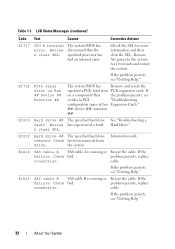
Remove is unable to determine its AC power to the system SEL. ##. Review & clear SEL. Remove AC power to the system for more Review & clear determined there has been information and then SEL. If the problem persists, see "Getting Help." LCD Status Messages (continued) Code Text Causes Corrective Actions ... Remove and reseat the reported a PCI system PCIe expansion cards. If the problem persists, see resides in the system. About Your System 31 Table 1-1. Remove Review & clear ##, device ##, function AC power to the system origin.
Remove is unable to determine its AC power to the system SEL. ##. Review & clear SEL. Remove AC power to the system for more Review & clear determined there has been information and then SEL. If the problem persists, see "Getting Help." LCD Status Messages (continued) Code Text Causes Corrective Actions ... Remove and reseat the reported a PCI system PCIe expansion cards. If the problem persists, see resides in the system. About Your System 31 Table 1-1. Remove Review & clear ##, device ##, function AC power to the system origin.
Hardware Owner's Manual
Page 32
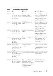
... ## The specified hard drive fault. E1812 Hard drive ## The specified hard drive removed. Check bad. See "Troubleshooting a Hard Drive." Review & clear SEL. E1A14 SAS cable A SAS cable A is missing or Reseat the cable. If the problem persists, see resides in ... the problem persists, see "Getting Help." 32 About Your System E1A15 SAS cable B SAS cable B is missing or Reseat the cable. Review has experienced a fault. & clear SEL. Table 1-1. problem persists, replace connection. problem persists, replace connection. Check has been removed from ...
... ## The specified hard drive fault. E1812 Hard drive ## The specified hard drive removed. Check bad. See "Troubleshooting a Hard Drive." Review & clear SEL. E1A14 SAS cable A SAS cable A is missing or Reseat the cable. If the problem persists, see resides in ... the problem persists, see "Getting Help." 32 About Your System E1A15 SAS cable B SAS cable B is missing or Reseat the cable. Review has experienced a fault. & clear SEL. Table 1-1. problem persists, replace connection. problem persists, replace connection. Check has been removed from ...
Hardware Owner's Manual
Page 35
... Status Messages (continued) Code Text Causes Corrective Actions E201C SMI System management initialization interrupt (SMI) failure. E201E POST memory test failure. See "Troubleshooting the Processor(s)." Review User Guide. See "Troubleshooting System Memory." Check DIMMs. BIOS POST memory test failure. POST. Table 1-1. If the problem persists, see "Getting Help." Power initialization failure...
... Status Messages (continued) Code Text Causes Corrective Actions E201C SMI System management initialization interrupt (SMI) failure. E201E POST memory test failure. See "Troubleshooting the Processor(s)." Review User Guide. See "Troubleshooting System Memory." Check DIMMs. BIOS POST memory test failure. POST. Table 1-1. If the problem persists, see "Getting Help." Power initialization failure...
Hardware Owner's Manual
Page 36
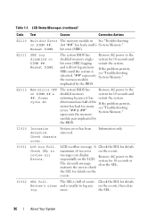
E2111 SBE log disabled on DIMM ## & ##. The system BIOS has Remove AC power to review all Errors. system for details on the events. E2113 Mem mirror OFF on DIMM ##. "## & ##" System Memory." I1910 Intrusion detected. I1911 LCD Log Full. .... Table 1-1. Reseat DIMM. and will not log anymore If the problem persists, SBEs until the system is unable to the disabled memory system for details Review & clear and is see "Troubleshooting errors. Check SEL to the disabled memory single- System Memory." Check chassis cover. System cover has been removed. slot ...
E2111 SBE log disabled on DIMM ## & ##. The system BIOS has Remove AC power to review all Errors. system for details on the events. E2113 Mem mirror OFF on DIMM ##. "## & ##" System Memory." I1910 Intrusion detected. I1911 LCD Log Full. .... Table 1-1. Reseat DIMM. and will not log anymore If the problem persists, SBEs until the system is unable to the disabled memory system for details Review & clear and is see "Troubleshooting errors. Check SEL to the disabled memory single- System Memory." Check chassis cover. System cover has been removed. slot ...
Hardware Owner's Manual
Page 43
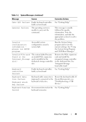
... is usually followed by specific information. dedicated storage controller slot. Table 1-2. This message is installed in the dedicated slot. Run the System Setup program and review the current settings. Remove the PCIe expansion card and install the integrated storage controller in the slot! About Your System 43 See "Getting Help." See...
... is usually followed by specific information. dedicated storage controller slot. Table 1-2. This message is installed in the dedicated slot. Run the System Setup program and review the current settings. Remove the PCIe expansion card and install the integrated storage controller in the slot! About Your System 43 See "Getting Help." See...

