

Glossary
Page 2
... - Electromagnetic interference. Embedded server management. An add-in card, such as NICs. DHCP - Dynamic random-access memory. control panel - DNS - See processor. EMI - coprocessor - DVD - Error checking and correction. DDR -
... - Electromagnetic interference. Embedded server management. An add-in card, such as NICs. DHCP - Dynamic random-access memory. control panel - DNS - See processor. EMI - coprocessor - DVD - Error checking and correction. DDR -

Glossary
Page 6
.... partition - You must usually be revised to run on your system. A standard for maintaining the date, time, and system configuration information. PDU - PowerEdge RAID controller. pixel - Pixels are arranged in a rack. A video resolution, such as 640 x 480, is associated with the fdisk command. POST...as a diskette drive or keyboard, connected to servers and storage systems in rows and columns to signal the processor about hardware errors. Before the operating system loads when you turn on another processor. CPU is an implementation-specific integer or pointer that is ...
.... partition - You must usually be revised to run on your system. A standard for maintaining the date, time, and system configuration information. PDU - PowerEdge RAID controller. pixel - Pixels are arranged in a rack. A video resolution, such as 640 x 480, is associated with the fdisk command. POST...as a diskette drive or keyboard, connected to servers and storage systems in rows and columns to signal the processor about hardware errors. Before the operating system loads when you turn on another processor. CPU is an implementation-specific integer or pointer that is ...

Glossary
Page 7
... A method of independent disks. Random-access memory. Your system contains some programs essential to the system BIOS and then display an error message on motherboard. SAN - An I /O port with a 9-pin connector that transfers data one that contains information supplementing or ...updating the product's documentation. Secure digital flash memory card. Allows hard drives to report errors and failures to its contents even after you call Dell for program instructions and data. RAID - Redundant array of providing data redundancy. See also mirroring...
... A method of independent disks. Random-access memory. Your system contains some programs essential to the system BIOS and then display an error message on motherboard. SAN - An I /O port with a 9-pin connector that transfers data one that contains information supplementing or ...updating the product's documentation. Secure digital flash memory card. Allows hard drives to report errors and failures to its contents even after you call Dell for program instructions and data. RAID - Redundant array of providing data redundancy. See also mirroring...
Dell PowerEdge Deployment Guide
Page 2
Reproduction of Microsoft Corporation in the United States and/or other countries. Dell, the DELL logo, and the DELL badge, Dell OpenManage, and PowerEdge are either trademarks or registered trademarks of this material in the United States and/or other ... IMPLIED WARRANTIES OF ANY KIND. © 2009 Dell Inc. For more information, contact Dell. Page ii All rights reserved. is strictly forbidden. PowerEdge Deployment Guide THIS WHITE PAPER IS FOR INFORMATIONAL PURPOSES ONLY, AND MAY CONTAIN TYPOGRAPHICAL ERRORS AND TECHNICAL INACCURACIES. Microsoft, Windows, and Windows ...
Reproduction of Microsoft Corporation in the United States and/or other countries. Dell, the DELL logo, and the DELL badge, Dell OpenManage, and PowerEdge are either trademarks or registered trademarks of this material in the United States and/or other ... IMPLIED WARRANTIES OF ANY KIND. © 2009 Dell Inc. For more information, contact Dell. Page ii All rights reserved. is strictly forbidden. PowerEdge Deployment Guide THIS WHITE PAPER IS FOR INFORMATIONAL PURPOSES ONLY, AND MAY CONTAIN TYPOGRAPHICAL ERRORS AND TECHNICAL INACCURACIES. Microsoft, Windows, and Windows ...
Dell PowerEdge Deployment Guide
Page 6
..., you will need to add the network adapter driver. For the 11th Generation PowerEdge servers, you will also need to support iSCSI and TOE. Microsoft Automated Deployment Service (ADS) Dell has observed a problem with Broadcom NetXtreme Devices for Installation of the installation due to... operating system installation is added per the Microsoft WDS / RIS documentation. Dell recommends that the mass storage driver for more information. When booting to the Deployment Agent, ADS gives the following error: Windows could not start due to build a bootable RAMDISK image. Depending...
..., you will need to add the network adapter driver. For the 11th Generation PowerEdge servers, you will also need to support iSCSI and TOE. Microsoft Automated Deployment Service (ADS) Dell has observed a problem with Broadcom NetXtreme Devices for Installation of the installation due to... operating system installation is added per the Microsoft WDS / RIS documentation. Dell recommends that the mass storage driver for more information. When booting to the Deployment Agent, ADS gives the following error: Windows could not start due to build a bootable RAMDISK image. Depending...
Dell PowerEdge Deployment Guide
Page 7
Page 5 PowerEdge Deployment Guide This error continues even after ensuring that all needed drivers are added to use WinPE instead of the default deployment agent. See the following Microsoft knowledge base article: http://support.microsoft.com/?id=970721 Using UEFI For additional information about using UEFI, see Deploying UEFI-Aware Operating Systems on Eleventh Generation Dell TM PowerEdgeTM Servers. The solution for this issue is to the PreSystem directory.
Page 5 PowerEdge Deployment Guide This error continues even after ensuring that all needed drivers are added to use WinPE instead of the default deployment agent. See the following Microsoft knowledge base article: http://support.microsoft.com/?id=970721 Using UEFI For additional information about using UEFI, see Deploying UEFI-Aware Operating Systems on Eleventh Generation Dell TM PowerEdgeTM Servers. The solution for this issue is to the PreSystem directory.
Deploying UEFI-Aware Operating Systems on Dell PowerEdge Servers
Page 2
...Dell. SUSE is strictly forbidden. Dell, the DELL logo, and the DELL badge, and PowerEdge are either trademarks or registered trademarks of Novell, Inc., in any manner whatsoever without the express written permission of Dell Inc. THIS WHITE PAPER IS FOR INFORMATIONAL PURPOSES ONLY, AND MAY CONTAIN TYPOGRAPHICAL ERRORS... AND TECHNICAL INACCURACIES. THE CONTENT IS PROVIDED AS IS, WITHOUT EXPRESS OR IMPLIED WARRANTIES OF ANY KIND. © 2009 Dell Inc. Reproduction of this material in the United States and...
...Dell. SUSE is strictly forbidden. Dell, the DELL logo, and the DELL badge, and PowerEdge are either trademarks or registered trademarks of Novell, Inc., in any manner whatsoever without the express written permission of Dell Inc. THIS WHITE PAPER IS FOR INFORMATIONAL PURPOSES ONLY, AND MAY CONTAIN TYPOGRAPHICAL ERRORS... AND TECHNICAL INACCURACIES. THE CONTENT IS PROVIDED AS IS, WITHOUT EXPRESS OR IMPLIED WARRANTIES OF ANY KIND. © 2009 Dell Inc. Reproduction of this material in the United States and...
Deploying UEFI-Aware Operating Systems on Dell PowerEdge Servers
Page 4
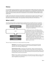
... There are available to the operating system and its boot time services and drivers, leaving only the run in memory unless an error is represented on the board of directors of a new framework, called an operating system boot loader, provides the necessary initialization routines... environment for Itanium. In 2005, several leading tech companies came together to create the first ever industry standard firmware interface specification - Dell is returned from EFI applications in that the driver stays resident in the preboot environment. While the Itanium chip was to create the...
... There are available to the operating system and its boot time services and drivers, leaving only the run in memory unless an error is represented on the board of directors of a new framework, called an operating system boot loader, provides the necessary initialization routines... environment for Itanium. In 2005, several leading tech companies came together to create the first ever industry standard firmware interface specification - Dell is returned from EFI applications in that the driver stays resident in the preboot environment. While the Itanium chip was to create the...
Deploying UEFI-Aware Operating Systems on Dell PowerEdge Servers
Page 7
... Data is automatically added to point to the following options are not listed. When the Boot Mode is no media in an optical drive), an error message displays along with a FAT32 file system, a menu displays to navigate to a file to select as a USB key, is detected in the \EFI\BOOT directory...
... Data is automatically added to point to the following options are not listed. When the Boot Mode is no media in an optical drive), an error message displays along with a FAT32 file system, a menu displays to navigate to a file to select as a USB key, is detected in the \EFI\BOOT directory...
Getting Started Guide
Page 10
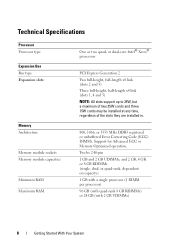
... 15W cards may be installed at any time, regardless of the slots they are installed in. 800, 1066, or 1333 MHz DDR3 registered or unbuffered Error Correcting Code (ECC) DIMMs. Support for Advanced ECC or Memory Optimized operation. Technical Specifications Processor Processor type Expansion Bus Bus type Expansion slots: Memory Architecture...
... 15W cards may be installed at any time, regardless of the slots they are installed in. 800, 1066, or 1333 MHz DDR3 registered or unbuffered Error Correcting Code (ECC) DIMMs. Support for Advanced ECC or Memory Optimized operation. Technical Specifications Processor Processor type Expansion Bus Bus type Expansion slots: Memory Architecture...
Hardware Owner's Manual
Page 4
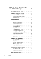
2 Using the System Setup Program and UEFI Boot Manager 57 Choosing the System Boot Mode 57 Entering the System Setup Program 58 Responding to Error Messages 58 Using the System Setup Program Navigation Keys 58 System Setup Options 59 Main Screen 59 Memory Settings Screen 61 Processor Settings Screen 62 ...
2 Using the System Setup Program and UEFI Boot Manager 57 Choosing the System Boot Mode 57 Entering the System Setup Program 58 Responding to Error Messages 58 Using the System Setup Program Navigation Keys 58 System Setup Options 59 Main Screen 59 Memory Settings Screen 61 Processor Settings Screen 62 ...
Hardware Owner's Manual
Page 12
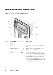
... 3 Description Covers the system's front-loading hard drives. The ports are USB 2.0-complaint. Use this button only if directed to troubleshoot software and device driver errors when using certain operating systems. This button can be pressed using the end of a paper clip. Connects USB devices to the system. Front-Panel Features...
... 3 Description Covers the system's front-loading hard drives. The ports are USB 2.0-complaint. Use this button only if directed to troubleshoot software and device driver errors when using certain operating systems. This button can be pressed using the end of a paper clip. Connects USB devices to the system. Front-Panel Features...
Hardware Owner's Manual
Page 14
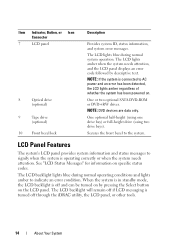
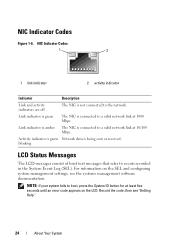
... Connector 7 LCD panel 8 Optical drive (optional) 9 Tape drive (optional) 10 Front bezel lock Description Provides system ID, status information, and system error messages. One or two optional SATA DVD-ROM or DVD+RW drives. See "LCD Status Messages" for information on the LCD panel. NOTE: If ... or other tools. 14 About Your System The LCD lights amber when the system needs attention, and the LCD panel displays an error code followed by pressing the Select button on specific status codes. The LCD lights blue during normal operating conditions and lights amber to ...
... Connector 7 LCD panel 8 Optical drive (optional) 9 Tape drive (optional) 10 Front bezel lock Description Provides system ID, status information, and system error messages. One or two optional SATA DVD-ROM or DVD+RW drives. See "LCD Status Messages" for information on the LCD panel. NOTE: If ... or other tools. 14 About Your System The LCD lights amber when the system needs attention, and the LCD panel displays an error code followed by pressing the Select button on specific status codes. The LCD lights blue during normal operating conditions and lights amber to ...
Hardware Owner's Manual
Page 16
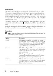
... during normal system operation when there are IP, Subnet (Sub), and Gateway (Gtw). When the system is selected, the available fields are no error messages. See the following tables for a list of the three navigation buttons (Select, Left, or Right) to view domain addresses. If Static ...format. See "LCD Status Messages" for information on the LCD Home screen. From the Home screen, press the Select button to display LCD error messages in a simplified user-friendly description. Two separate DNS entries are asked to display by default on the Home screen. 16 About Your...
... during normal system operation when there are IP, Subnet (Sub), and Gateway (Gtw). When the system is selected, the available fields are no error messages. See the following tables for a list of the three navigation buttons (Select, Left, or Right) to view domain addresses. If Static ...format. See "LCD Status Messages" for information on the LCD Home screen. From the Home screen, press the Select button to display LCD error messages in a simplified user-friendly description. Two separate DNS entries are asked to display by default on the Home screen. 16 About Your...
Hardware Owner's Manual
Page 22
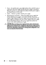
... that matches the capacity of the other power supply (a High Output 870-W power supply and an Energy Smart 570-W power supply are installed in an error condition and unexpected system shutdown. To change from a High Output configuration to make a matched pair can result in the same system). Replace the power supply...
... that matches the capacity of the other power supply (a High Output 870-W power supply and an Energy Smart 570-W power supply are installed in an error condition and unexpected system shutdown. To change from a High Output configuration to make a matched pair can result in the same system). Replace the power supply...
Hardware Owner's Manual
Page 24
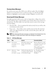
... Messages The LCD messages consist of brief text messages that refer to boot, press the System ID button for at least five seconds until an error code appears on the SEL and configuring system management settings, see "Getting Help." 24 About Your System
... Messages The LCD messages consist of brief text messages that refer to boot, press the System ID button for at least five seconds until an error code appears on the SEL and configuring system management settings, see "Getting Help." 24 About Your System
Hardware Owner's Manual
Page 25
... with sensors, such as temperature, voltage, fans, and so on, the LCD message is automatically removed when that sensor returns to view the error. Turn off the system and disconnect it from the display: • Clear the SEL - Remove AC power to view the list of the... allowed range. of errors or status messages. Press the Select button to the system for 10 seconds and restart the system. wait approximately ten seconds, reconnect the power...
... with sensors, such as temperature, voltage, fans, and so on, the LCD message is automatically removed when that sensor returns to view the error. Turn off the system and disconnect it from the display: • Clear the SEL - Remove AC power to view the list of the... allowed range. of errors or status messages. Press the Select button to the system for 10 seconds and restart the system. wait approximately ten seconds, reconnect the power...
Hardware Owner's Manual
Page 27
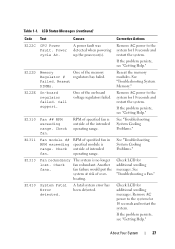
... Call support. Remove AC power to the system for additional scrolling messages. E1310 Fan ## RPM exceeding range. A fatal system error has been detected. Remove AC power to the system for additional scrolling messages. If the problem persists, see "Getting Help." ... the problem persists, see "Getting Help." Another fans. Check LCD for 10 seconds and restart the system. E1410 System Fatal Error detected. See "Troubleshooting System Cooling Problems." See "Troubleshooting System Memory." E122E On-board regulator failed. heating. About Your System ...
... Call support. Remove AC power to the system for additional scrolling messages. E1310 Fan ## RPM exceeding range. A fatal system error has been detected. Remove AC power to the system for additional scrolling messages. If the problem persists, see "Getting Help." ... the problem persists, see "Getting Help." Another fans. Check LCD for 10 seconds and restart the system. E1410 System Fatal Error detected. See "Troubleshooting System Cooling Problems." See "Troubleshooting System Memory." E122E On-board regulator failed. heating. About Your System ...
Hardware Owner's Manual
Page 28
... out Ensure that your system's Getting Started Guide. E141C Unsupported Processors are properly range. E1420 CPU Bus parity The system BIOS has error. Power cycle AC. Remove AC power to the system for 10 seconds and restart the system. restart the system. Remove AC power... to the system for 10 seconds and error. If the problem persists, see "Getting Help." Specified processor is seated properly. E1418 CPU # not detected. If the problem persists, see...
... out Ensure that your system's Getting Started Guide. E141C Unsupported Processors are properly range. E1420 CPU Bus parity The system BIOS has error. Power cycle AC. Remove AC power to the system for 10 seconds and restart the system. restart the system. Remove AC power... to the system for 10 seconds and error. If the problem persists, see "Getting Help." Specified processor is seated properly. E1418 CPU # not detected. If the problem persists, see...
Hardware Owner's Manual
Page 29
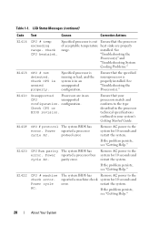
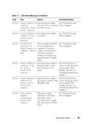
... supply. If the remaining power supply fails, the system will shut down. E1614 Power Supply # Specified power supply (### W) error. has failed. See "Troubleshooting Power Supplies." E1618 Predictive A power supply fan failure, See "Troubleshooting failure on an over-temperature Power ...removed or is no longer redundant. Check PSU cables. About Your System 29 E1624 Lost power supply redundancy. Check supply communication PSU. error has caused the predictive warning of the source for the specified power supply. The power supply subsystem is missing Power Supplies." Table 1-1.
... supply. If the remaining power supply fails, the system will shut down. E1614 Power Supply # Specified power supply (### W) error. has failed. See "Troubleshooting Power Supplies." E1618 Predictive A power supply fan failure, See "Troubleshooting failure on an over-temperature Power ...removed or is no longer redundant. Check PSU cables. About Your System 29 E1624 Lost power supply redundancy. Check supply communication PSU. error has caused the predictive warning of the source for the specified power supply. The power supply subsystem is missing Power Supplies." Table 1-1.


