
Deploying UEFI-Aware Operating Systems on Dell PowerEdge Servers
Page 7
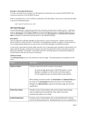
... menu: Option Description Add Boot Option Provides a menu from which removes them from the boot option list. In UEFI boot mode, it replaces both the BIOS Boot Manager and the boot configuration options in the UEFI Boot Manager; The Description identifies the device in the BIOS Setup... option, the Description and Optional Data can be grayed out and display "Unavailable." When the Boot Mode is not bootable (for example, a hard‐disk drive has been removed), the option will continue to be listed, but will be re‐enabled from Page 5 For PXE‐capable devices,...
... menu: Option Description Add Boot Option Provides a menu from which removes them from the boot option list. In UEFI boot mode, it replaces both the BIOS Boot Manager and the boot configuration options in the UEFI Boot Manager; The Description identifies the device in the BIOS Setup... option, the Description and Optional Data can be grayed out and display "Unavailable." When the Boot Mode is not bootable (for example, a hard‐disk drive has been removed), the option will continue to be listed, but will be re‐enabled from Page 5 For PXE‐capable devices,...

Hardware Owner's Manual
Page 35
... persists, see "Getting Help" on page 185. problem persists, replace connection. If the failure. problem persists, replace connection. USB cable to the control panel is bad. Table 1-2. LCD Status Messages (continued) Code Text Causes Corrective Actions E1810 Hard drive ## The specified hard drive fault. E1812 Hard drive ## The specified hard drive removed. the system. E1920 iDRAC6 Upgrade The iDRAC6 Express...
... persists, see "Getting Help" on page 185. problem persists, replace connection. If the failure. problem persists, replace connection. USB cable to the control panel is bad. Table 1-2. LCD Status Messages (continued) Code Text Causes Corrective Actions E1810 Hard drive ## The specified hard drive fault. E1812 Hard drive ## The specified hard drive removed. the system. E1920 iDRAC6 Upgrade The iDRAC6 Express...
Hardware Owner's Manual
Page 51
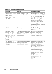
...modules are properly connected. About Your System 51 device not found The operating system cannot Replace the optical medium, read from the hard drive, USB medium, or USB optical drive, or USB device, device. System Messages (continued) Message Causes Corrective Actions Plug ...sector is no device connected Information only. "Troubleshooting a USB Device" on page 156, "Troubleshooting an Optical Drive" on page 165, or "Troubleshooting a Hard Drive" on page 171. Quad rank DIMM Invalid memory detected after configuration. SATA Port x There is are ...
...modules are properly connected. About Your System 51 device not found The operating system cannot Replace the optical medium, read from the hard drive, USB medium, or USB optical drive, or USB device, device. System Messages (continued) Message Causes Corrective Actions Plug ...sector is no device connected Information only. "Troubleshooting a USB Device" on page 156, "Troubleshooting an Optical Drive" on page 165, or "Troubleshooting a Hard Drive" on page 171. Quad rank DIMM Invalid memory detected after configuration. SATA Port x There is are ...
Hardware Owner's Manual
Page 52
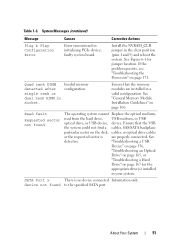
Table 1-3. System Messages (continued) Message Causes Corrective Actions Sector not found Faulty hard drive, USB Seek error device, or USB medium. See "Troubleshooting System Memory" on page 185. Shutdown failure General system error. See "Getting Help" on page 162...been added or removed, check the SEL to determine if single-bit or multi-bit errors were detected and replace the faulty memory module. See "Troubleshooting a USB Device" on page 156 or "Troubleshooting a Hard Drive" on page 106. For sparing mode, matched sets of Memory has been added or system memory has ...
Table 1-3. System Messages (continued) Message Causes Corrective Actions Sector not found Faulty hard drive, USB Seek error device, or USB medium. See "Troubleshooting System Memory" on page 185. Shutdown failure General system error. See "Getting Help" on page 162...been added or removed, check the SEL to determine if single-bit or multi-bit errors were detected and replace the faulty memory module. See "Troubleshooting a USB Device" on page 156 or "Troubleshooting a Hard Drive" on page 106. For sparing mode, matched sets of Memory has been added or system memory has ...
Hardware Owner's Manual
Page 58
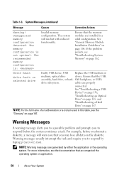
...system. SAS backplane, or SATA drive subsystem. See "Troubleshooting a USB Device" on page 156, "Troubleshooting an Optical Drive" on page 165, and "Troubleshooting a Hard Drive" on selected drive Faulty USB device, USB Replace the USB medium or medium, optical drive device. Warning Messages A warning ...information, see "Troubleshooting System Memory" on the diskette. Table 1-3. The system will warn you that the USB, assembly, hard drive, or hard- NOTE: For the full name of an abbreviation or acronym used in a valid configuration. cables are installed in this ...
...system. SAS backplane, or SATA drive subsystem. See "Troubleshooting a USB Device" on page 156, "Troubleshooting an Optical Drive" on page 165, and "Troubleshooting a Hard Drive" on selected drive Faulty USB device, USB Replace the USB medium or medium, optical drive device. Warning Messages A warning ...information, see "Troubleshooting System Memory" on the diskette. Table 1-3. The system will warn you that the USB, assembly, hard drive, or hard- NOTE: For the full name of an abbreviation or acronym used in a valid configuration. cables are installed in this ...
Hardware Owner's Manual
Page 98
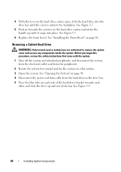
... other and slide the drive up and out of the hard-drive bracket towards the system) on the hard drive carrier and rotate the handle up until the carrier contacts the backplane. See "Installing the Front Bezel" on a flat surface. 3 Open the system. See Figure 3-9. 98 Installing System Components See Figure 3-7. 6 Replace the front bezel. See...
... other and slide the drive up and out of the hard-drive bracket towards the system) on the hard drive carrier and rotate the handle up until the carrier contacts the backplane. See "Installing the Front Bezel" on a flat surface. 3 Open the system. See Figure 3-9. 98 Installing System Components See Figure 3-7. 6 Replace the front bezel. See...

Hardware Owner's Manual
Page 100
... Figure 3-10. Before you are authorized to an electrical outlet. 11 Turn on the system and attached peripherals Installing a Cabled Hard Drive WARNING: Only trained service technicians are not replacing the hard drive, remove the drive from the peripherals. 2 Rotate the system feet inward and lay the system on a flat, stable surface. 9 Rotate the system feet...
... Figure 3-10. Before you are authorized to an electrical outlet. 11 Turn on the system and attached peripherals Installing a Cabled Hard Drive WARNING: Only trained service technicians are not replacing the hard drive, remove the drive from the peripherals. 2 Rotate the system feet inward and lay the system on a flat, stable surface. 9 Rotate the system feet...

Hardware Owner's Manual
Page 145
... system on a flat, stable surface. 6 Rotate the system feet outward. 7 Replace the front bezel. See "Installing the Front Bezel" on page 86. 8 Reattach any of the components inside the system. See "Removing the Cooling Shroud" on page 94. 6 Disconnect all the hard drives. See "Opening the System" on the system and attached peripherals...
... system on a flat, stable surface. 6 Rotate the system feet outward. 7 Replace the front bezel. See "Installing the Front Bezel" on page 86. 8 Reattach any of the components inside the system. See "Removing the Cooling Shroud" on page 94. 6 Disconnect all the hard drives. See "Opening the System" on the system and attached peripherals...

Hardware Owner's Manual
Page 147
...are authorized to an electrical outlet. 9 Turn on the system and attached peripherals. See "Installing a Hot-Swap Hard Drive" on page 93. 7 Close the system. Installing System Components 147 See "Closing the System" on the ...Replace the cooling shroud. Before you begin this procedure, review the safety instructions that were routed over the notch in the SAS backplane. 4 Reconnect the cables connected to the SAS backplane (see Figure 3-27): • SAS A cable • SAS B cable • Hard drive activity indicator cable • Backplane power cable 5 Replace all the hard drives...
...are authorized to an electrical outlet. 9 Turn on the system and attached peripherals. See "Installing a Hot-Swap Hard Drive" on page 93. 7 Close the system. Installing System Components 147 See "Closing the System" on the ...Replace the cooling shroud. Before you begin this procedure, review the safety instructions that were routed over the notch in the SAS backplane. 4 Reconnect the cables connected to the SAS backplane (see Figure 3-27): • SAS A cable • SAS B cable • Hard drive activity indicator cable • Backplane power cable 5 Replace all the hard drives...

Hardware Owner's Manual
Page 150
... 85. 3 Rotate the system feet inward and lay the system on page 93. 5 Replace the power supplies. System Board (Service-Only Procedure) WARNING: The heat sink can access the encrypted data on your hard drive(s). See "Installing the Cooling Shroud" on a flat surface. 150 Installing System Components See ... safety instructions that the system has sufficient time to remove the system cover and access any peripherals and connect the system to replace the system board, you must supply the recovery key when you restart your system or program before removing the system board. ...
... 85. 3 Rotate the system feet inward and lay the system on page 93. 5 Replace the power supplies. System Board (Service-Only Procedure) WARNING: The heat sink can access the encrypted data on your hard drive(s). See "Installing the Cooling Shroud" on a flat surface. 150 Installing System Components See ... safety instructions that the system has sufficient time to remove the system cover and access any peripherals and connect the system to replace the system board, you must supply the recovery key when you restart your system or program before removing the system board. ...

Hardware Owner's Manual
Page 162
... page 185. If the tests fail, see "Getting Help" on its system configuration information. If the date and time are properly connected. 5 Replace the cooling shroud. NOTE: Some software may cause the system time to the electrical outlet and turn on page 61. 2 Turn off for long... Enter the System Setup program. • Fans • Processors and heat sinks • Memory modules • Hard-drive carriers 4 Ensure that all cables are not correct in the System Setup program, replace the battery. See "Closing the System" on page 91. 7 Place the system upright and on page 185. See...
... page 185. If the tests fail, see "Getting Help" on its system configuration information. If the date and time are properly connected. 5 Replace the cooling shroud. NOTE: Some software may cause the system time to the electrical outlet and turn on page 61. 2 Turn off for long... Enter the System Setup program. • Fans • Processors and heat sinks • Memory modules • Hard-drive carriers 4 Ensure that all cables are not correct in the System Setup program, replace the battery. See "Closing the System" on page 91. 7 Place the system upright and on page 185. See...
Hardware Owner's Manual
Page 199
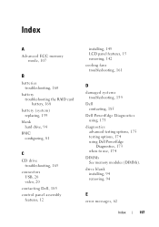
... card battery, 168 battery (system) replacing, 139 blank hard drive, 94 BMC configuring, 81 C CD drive troubleshooting, 165 connectors USB, 20 video, 20 contacting Dell, 185 control panel assembly features, 12 installing, 145 LCD panel features, 15 removing, 142 cooling fans troubleshooting, 161 D damaged systems troubleshooting, 159 Dell contacting, 185 Dell PowerEdge Diagnostics using, 173 diagnostics advanced testing...
... card battery, 168 battery (system) replacing, 139 blank hard drive, 94 BMC configuring, 81 C CD drive troubleshooting, 165 connectors USB, 20 video, 20 contacting Dell, 185 control panel assembly features, 12 installing, 145 LCD panel features, 15 removing, 142 cooling fans troubleshooting, 161 D damaged systems troubleshooting, 159 Dell contacting, 185 Dell PowerEdge Diagnostics using, 173 diagnostics advanced testing...

Hardware Owner's Manual
Page 201
... indicators, 23 troubleshooting, 161 processor installing, 138 removing, 135 upgrades, 135 R removing control panel assembly, 142 expansion cards, 118 hard drive (cabled), 98 hard drive blank, 94 hard drives (hot-pluggable), 94 memory modules, 113 processor, 135 replacing system battery, 139 Index 199 Memory Mirroring, 108 Optimizer, 108 memory modules (DIMMs) configuring, 106 installing, 110 RDIMM configurations...
... indicators, 23 troubleshooting, 161 processor installing, 138 removing, 135 upgrades, 135 R removing control panel assembly, 142 expansion cards, 118 hard drive (cabled), 98 hard drive blank, 94 hard drives (hot-pluggable), 94 memory modules, 113 processor, 135 replacing system battery, 139 Index 199 Memory Mirroring, 108 Optimizer, 108 memory modules (DIMMs) configuring, 106 installing, 110 RDIMM configurations...


