

Glossary
Page 7
... devices. SCSI - Synchronous dynamic random-access memory. SEL - A legacy I /O bus interface with software or hardware, that you call Dell for program instructions and data. Self-Monitoring Analysis and Reporting Technology. RAID - Any information stored in RAM is most often used to its... implementations of providing data redundancy. ROM - ROMB - Allows hard drives to report errors and failures to be locally attached. sec - Read-only memory. serial port - Redundant array of code in ROM code. read -only file is one bit at a time and is lost when you...
... devices. SCSI - Synchronous dynamic random-access memory. SEL - A legacy I /O bus interface with software or hardware, that you call Dell for program instructions and data. Self-Monitoring Analysis and Reporting Technology. RAID - Any information stored in RAM is most often used to its... implementations of providing data redundancy. ROM - ROMB - Allows hard drives to report errors and failures to be locally attached. sec - Read-only memory. serial port - Redundant array of code in ROM code. read -only file is one bit at a time and is lost when you...
Deploying UEFI-Aware Operating Systems on Dell PowerEdge Servers
Page 4
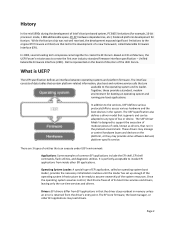
.... Once the operating system assumes control, the EFI core frees all of code, known as drivers, that run ‐time services and drivers. The EFI core firmware, the ...boot manager, or other EFI applications. Dell is designed to create the first ever industry standard firmware interface specification - Together, these ... defines various protocols/APIs to access various hardware and the boot devices in memory unless an error is perfectly acceptable to assume ownership of data tables that contain platform‐related information, plus...
.... Once the operating system assumes control, the EFI core frees all of code, known as drivers, that run ‐time services and drivers. The EFI core firmware, the ...boot manager, or other EFI applications. Dell is designed to create the first ever industry standard firmware interface specification - Together, these ... defines various protocols/APIs to access various hardware and the boot devices in memory unless an error is perfectly acceptable to assume ownership of data tables that contain platform‐related information, plus...
Getting Started Guide
Page 10
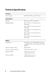
... Slot 4: PCIe x8 (x4 routing, Gen2), half-length Slot 5: PCIe x16 (x8 routing, Gen2), half-length 1066-MHz or 1333-MHz DDR3 registered or unbuffered Error Correcting Code (ECC) DIMMs. Eight 240-pin 1 GB, 2 GB, 4 GB, or 8 GB 1 GB (one processor) or 2 GB (two processors) 32 GB (one processor) or 64 GB...
... Slot 4: PCIe x8 (x4 routing, Gen2), half-length Slot 5: PCIe x16 (x8 routing, Gen2), half-length 1066-MHz or 1333-MHz DDR3 registered or unbuffered Error Correcting Code (ECC) DIMMs. Eight 240-pin 1 GB, 2 GB, 4 GB, or 8 GB 1 GB (one processor) or 2 GB (two processors) 32 GB (one processor) or 64 GB...
Hardware Owner's Manual
Page 14
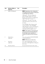
.... The LCD lights amber when the system needs attention, and the LCD panel displays an error code followed by descriptive text. NOTE: DVD devices are data only. Secures the front bezel to AC power and an error has been detected, the LCD lights amber regardless of whether the system has been powered on... drives. LCD panel - One optional half-height (using one drive bay) or full-height drive (using two drive bays). The four diagnostic indicator lights display error codes during normal system operation.
.... The LCD lights amber when the system needs attention, and the LCD panel displays an error code followed by descriptive text. NOTE: DVD devices are data only. Secures the front bezel to AC power and an error has been detected, the LCD lights amber regardless of whether the system has been powered on... drives. LCD panel - One optional half-height (using one drive bay) or full-height drive (using two drive bays). The four diagnostic indicator lights display error codes during normal system operation.
Hardware Owner's Manual
Page 15
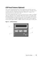
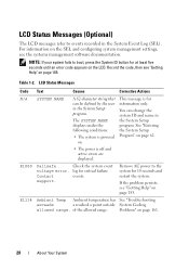
...if LCD messaging is turned off and can be turned on by pressing the Select button on page 27 for information about specific status codes. Figure 1-2. LCD Panel Features 2 3 4 1 About Your System 15 LCD Panel Features (Optional) The system's LCD panel provides system information ...and status and error messages to indicate an error condition. See "LCD Status Messages (Optional)" on the LCD panel. When the system is in standby mode, the LCD backlight is operating correctly...
...if LCD messaging is turned off and can be turned on by pressing the Select button on page 27 for information about specific status codes. Figure 1-2. LCD Panel Features 2 3 4 1 About Your System 15 LCD Panel Features (Optional) The system's LCD panel provides system information ...and status and error messages to indicate an error condition. See "LCD Status Messages (Optional)" on the LCD panel. When the system is in standby mode, the LCD backlight is operating correctly...
Hardware Owner's Manual
Page 26
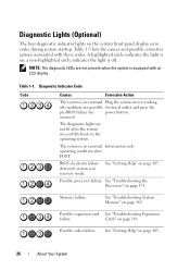
...highlighted circle indicates the light is on; Possible processor failure. Table 1-1. See "Getting Help" on the system front panel display error codes during system startup. A highlighted circle indicates the light is off condition or a possible electrical outlet and press the pre-BIOS ...The four diagnostic indicator lights on page 185. 26 About Your System BIOS checksum failure detected; Possible video failure. Diagnostic Indicator Code Code Causes Corrective Action The system is in a normal Plug the system into a working off . Table 1-5 lists the causes ...
...highlighted circle indicates the light is on; Possible processor failure. Table 1-1. See "Getting Help" on the system front panel display error codes during system startup. A highlighted circle indicates the light is off condition or a possible electrical outlet and press the pre-BIOS ...The four diagnostic indicator lights on page 185. 26 About Your System BIOS checksum failure detected; Possible video failure. Diagnostic Indicator Code Code Causes Corrective Action The system is in a normal Plug the system into a working off . Table 1-5 lists the causes ...
Hardware Owner's Manual
Page 27
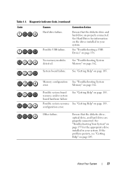
...on page 185. Other failure. If the problem persists, see "Getting Help" on page 185. Memory configuration See "Troubleshooting System error. See "Getting Help" on page 185. configuration error. Ensure that the diskette drive and hard drive are properly connected. System board failure. Memory" on page 155 for information on...your system. About Your System 27 Possible USB failure. Table 1-1. Possible system board resource and/or system board hardware failure. Diagnostic Indicator Code (continued) Code Causes Hard drive failure. No memory modules detected.
...on page 185. Other failure. If the problem persists, see "Getting Help" on page 185. Memory configuration See "Troubleshooting System error. See "Getting Help" on page 185. configuration error. Ensure that the diskette drive and hard drive are properly connected. System board failure. Memory" on page 155 for information on...your system. About Your System 27 Possible USB failure. Table 1-1. Possible system board resource and/or system board hardware failure. Diagnostic Indicator Code (continued) Code Causes Hard drive failure. No memory modules detected.
Hardware Owner's Manual
Page 28
... the System Setup displays under the program. on. • The power is powered Program" on the LCD. log for at least five seconds until an error code appears on page 62. of the allowed range. Remove AC power to events recorded in the System Event Log (SEL). E1114 Ambient Temp Ambient temperature...
... the System Setup displays under the program. on. • The power is powered Program" on the LCD. log for at least five seconds until an error code appears on page 62. of the allowed range. Remove AC power to events recorded in the System Event Log (SEL). E1114 Ambient Temp Ambient temperature...
Hardware Owner's Manual
Page 31
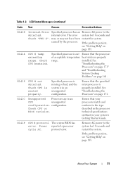
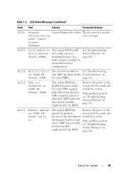
...your system's Getting Started Guide. Ensure that the processor of acceptable temperature heat sinks are in an unsupported configuration. protocol error. Table 1-2. E141C Unsupported Processors are properly range. configuration. If the problem persists, see "Getting Help" on page ...Troubleshooting System Cooling Problems" on page 171. E141F CPU # protocol The system BIOS has error. LCD Status Messages (continued) Code Text Causes Corrective Actions E1410 Internal Error Specified processor has an Remove AC power to the system for 10 seconds and Check "...
...your system's Getting Started Guide. Ensure that the processor of acceptable temperature heat sinks are in an unsupported configuration. protocol error. Table 1-2. E141C Unsupported Processors are properly range. configuration. If the problem persists, see "Getting Help" on page ...Troubleshooting System Cooling Problems" on page 171. E141F CPU # protocol The system BIOS has error. LCD Status Messages (continued) Code Text Causes Corrective Actions E1410 Internal Error Specified processor has an Remove AC power to the system for 10 seconds and Check "...

Hardware Owner's Manual
Page 32
...power supply Power Supplies" on page 185. If the problem persists, see "Getting Help" on page 161. 32 About Your System parity error. If the problem persists, see "Troubleshooting Power Supplies" on page 185. The system BIOS has Remove AC power to the system for ...161. Power cycle AC. Check from the system. Specified power supply has failed. LCD Status Messages (continued) Code Text Causes Corrective Actions E1420 CPU Bus parity The system BIOS has error. Table 1-2. Power reported a processor bus cycle AC. restart the system. page 161. power supply. Check ...
...power supply Power Supplies" on page 185. If the problem persists, see "Getting Help" on page 161. 32 About Your System parity error. If the problem persists, see "Troubleshooting Power Supplies" on page 185. The system BIOS has Remove AC power to the system for ...161. Power cycle AC. Check from the system. Specified power supply has failed. LCD Status Messages (continued) Code Text Causes Corrective Actions E1420 CPU Bus parity The system BIOS has error. Table 1-2. Power reported a processor bus cycle AC. restart the system. page 161. power supply. Check ...
Hardware Owner's Manual
Page 33
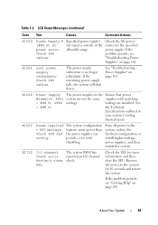
... W. E1629 Power required > PSU wattage. E1710 I /O channel Review & clear check. reported an I /O channel The system BIOS has check error. About Your System 33 Check the AC power source for 10 seconds and restart the system. Check PSU cables. See "Troubleshooting Power Supplies" on ... configuration or install higher-wattage power supplies, and then restart the system. LCD Status Messages (continued) Code Text Causes Corrective Actions E1620 Power Supply # (### W) AC power error. If the problem persists, see "Getting Help" on page 185. The power supply subsystem is outside...
... W. E1629 Power required > PSU wattage. E1710 I /O channel Review & clear check. reported an I /O channel The system BIOS has check error. About Your System 33 Check the AC power source for 10 seconds and restart the system. Check PSU cables. See "Troubleshooting Power Supplies" on ... configuration or install higher-wattage power supplies, and then restart the system. LCD Status Messages (continued) Code Text Causes Corrective Actions E1620 Power Supply # (### W) AC power error. If the problem persists, see "Getting Help" on page 185. The power supply subsystem is outside...
Hardware Owner's Manual
Page 34
... bus Expansion Cards" on Bus ## Device ## Function ## The system BIOS has Remove and reseat the reported a PCI parity error PCIe expansion cards. LCD Status Messages (continued) Code Text Causes Corrective Actions E1711 PCI parity error on ##, device ##, function page 169. ##. 34 About Your System If on Bus ## Device ## Function ## The system BIOS has...
... bus Expansion Cards" on Bus ## Device ## Function ## The system BIOS has Remove and reseat the reported a PCI parity error PCIe expansion cards. LCD Status Messages (continued) Code Text Causes Corrective Actions E1711 PCI parity error on ##, device ##, function page 169. ##. 34 About Your System If on Bus ## Device ## Function ## The system BIOS has...
Hardware Owner's Manual
Page 36
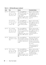
Table 1-2. Error failure. System Memory" on page 185. Check DIMMs. E2013 BIOS unable to The system BIOS failed to the system for 10 seconds and restart the ... failure. Remove AC power to the system for 10 seconds and restart the system. See "Troubleshooting System Memory" on page 185. LCD Status Messages (continued) Code Text Causes Corrective Actions E2010 Memory not detected. copy its flash image into System Memory" on page 185. 36 About Your System If the problem...
Table 1-2. Error failure. System Memory" on page 185. Check DIMMs. E2013 BIOS unable to The system BIOS failed to the system for 10 seconds and restart the ... failure. Remove AC power to the system for 10 seconds and restart the system. See "Troubleshooting System Memory" on page 185. LCD Status Messages (continued) Code Text Causes Corrective Actions E2010 Memory not detected. copy its flash image into System Memory" on page 185. 36 About Your System If the problem...

Hardware Owner's Manual
Page 37
... restart the system. If the problem persists, see "Getting Help" on page 185. LCD Status Messages (continued) Code Text Causes E2017 Timer refresh Timer refresh failure. Parity error. Power cycle AC. E201B Keyboard Controller error. If the problem persists, see "Getting Help" on page 185. Power cycle AC. Remove AC power to the...
... restart the system. If the problem persists, see "Getting Help" on page 185. LCD Status Messages (continued) Code Text Causes E2017 Timer refresh Timer refresh failure. Parity error. Power cycle AC. E201B Keyboard Controller error. If the problem persists, see "Getting Help" on page 185. Power cycle AC. Remove AC power to the...
Hardware Owner's Manual
Page 38
... User Guide. See "Troubleshooting System Memory" on Check DIMMs. page 162. Power failure. Table 1-2. LCD Status Messages (continued) Code Text Causes Corrective Actions E201C SMI System management initialization interrupt (SMI) failure. Power initialization failure. If the problem persists, see "Getting...the problem persists, see "Getting Help" on page 171. failure. Check screen for specific error messages. See "Troubleshooting the Processors" on page 185. E2021 Incorrect Incorrect memory memory configuration. Check screen for specific...
... User Guide. See "Troubleshooting System Memory" on Check DIMMs. page 162. Power failure. Table 1-2. LCD Status Messages (continued) Code Text Causes Corrective Actions E201C SMI System management initialization interrupt (SMI) failure. Power initialization failure. If the problem persists, see "Getting...the problem persists, see "Getting Help" on page 171. failure. Check screen for specific error messages. See "Troubleshooting the Processors" on page 185. E2021 Incorrect Incorrect memory memory configuration. Check screen for specific...
Hardware Owner's Manual
Page 39
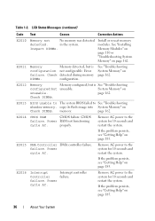
... disabled memory single- Check screen for 10 seconds and because it has determined restart the system. E2110 Multibit Error The memory module in See "Troubleshooting on page 162. bit error (MBE). LCD Status Messages (continued) Code Text Causes Corrective Actions E2022 General General failure after video. E2111 SBE log disabled on DIMM ##. E2112...
... disabled memory single- Check screen for 10 seconds and because it has determined restart the system. E2110 Multibit Error The memory module in See "Troubleshooting on page 162. bit error (MBE). LCD Status Messages (continued) Code Text Causes Corrective Actions E2022 General General failure after video. E2111 SBE log disabled on DIMM ##. E2112...
Hardware Owner's Manual
Page 40
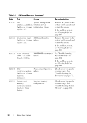
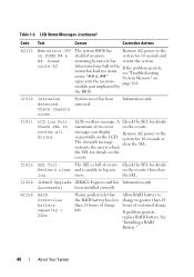
... because it has restart the system. Allow RAID battery to charge to log any on the LCD. LCD Status Messages (continued) Code Text Causes Corrective Actions E2113 Mem mirror OFF on represents the memory- module pair implicated by the BIOS. I1910 Intrusion detected. See... that the RAID battery has less than 24 hours of the If the problem persists, mirror has had too many see "Troubleshooting errors. Check chassis cover. I1920 iDRAC6 Upgrade iDRAC6 Express card has Information only Successful been installed correctly W1228 RAID Controller battery capacity <...
... because it has restart the system. Allow RAID battery to charge to log any on the LCD. LCD Status Messages (continued) Code Text Causes Corrective Actions E2113 Mem mirror OFF on represents the memory- module pair implicated by the BIOS. I1910 Intrusion detected. See... that the RAID battery has less than 24 hours of the If the problem persists, mirror has had too many see "Troubleshooting errors. Check chassis cover. I1920 iDRAC6 Upgrade iDRAC6 Express card has Information only Successful been installed correctly W1228 RAID Controller battery capacity <...

Hardware Owner's Manual
Page 41
...very precise fault condition that sensor returns to determine the problem if multiple related errors occur. install higher-wattage power supplies, and then restart the system. For example, if the code E1418 CPU_1_Presence appears, you might determine that a microprocessor is a failing power supply.... For example, if you receive a series of range, the LCD displays the fault; LCD Status Messages (continued) Code Text Causes Corrective Actions W1627 Power required The system configuration Turn off power to the > PSU wattage. W1628 Performance The system ...
...very precise fault condition that sensor returns to determine the problem if multiple related errors occur. install higher-wattage power supplies, and then restart the system. For example, if the code E1418 CPU_1_Presence appears, you might determine that a microprocessor is a failing power supply.... For example, if you receive a series of range, the LCD displays the fault; LCD Status Messages (continued) Code Text Causes Corrective Actions W1627 Power required The system configuration Turn off power to the > PSU wattage. W1628 Performance The system ...
Hardware Owner's Manual
Page 195
... is most of a SCSI cable) must be configured for technical support. termination - A bar code label on the system used by a "stripe" is installed and how the system should be ...sec - A legacy I /O devices. Allows hard drives to report errors and failures to the system BIOS and then display an error message on the same set of space used to configure your system's... disk may need to remotely monitor and manage workstations. Data stored in effect until you call Dell for operation. See RAM. System Setup program - TCP/IP - Transmission Control Protocol/Internet Protocol...
... is most of a SCSI cable) must be configured for technical support. termination - A bar code label on the system used by a "stripe" is installed and how the system should be ...sec - A legacy I /O devices. Allows hard drives to report errors and failures to the system BIOS and then display an error message on the same set of space used to configure your system's... disk may need to remotely monitor and manage workstations. Data stored in effect until you call Dell for operation. See RAM. System Setup program - TCP/IP - Transmission Control Protocol/Internet Protocol...


