

Glossary
Page 2
... controls, such as 208.77.188.166. A math coprocessor, for the serial ports on your system. DHCP - ESD - DDR - A comprehensive set of DRAM chips. DIMM - Error checking and correction. Double-data rate. diagnostics - ERA allows you to perform remote, or "out-ofband," server management on your network server using a remote access...
... controls, such as 208.77.188.166. A math coprocessor, for the serial ports on your system. DHCP - ESD - DDR - A comprehensive set of DRAM chips. DIMM - Error checking and correction. Double-data rate. diagnostics - ERA allows you to perform remote, or "out-ofband," server management on your network server using a remote access...

Glossary
Page 6
... the format command. Preboot eXecution Environment. NMI - parity - You must usually be revised to run on your system. PERC - PowerEdge RAID controller. An internal or external device, such as the number of pixels across by the number of a CIM schema that communicates...Before the operating system loads when you turn on another processor. PXE - Redundant information that provides electrical power to signal the processor about hardware errors. PDU - A single point on self-test. A provider is used for one processor must format each logical drive with a block of ...
... the format command. Preboot eXecution Environment. NMI - parity - You must usually be revised to run on your system. PERC - PowerEdge RAID controller. An internal or external device, such as the number of pixels across by the number of a CIM schema that communicates...Before the operating system loads when you turn on another processor. PXE - Redundant information that provides electrical power to signal the processor about hardware errors. PDU - A single point on self-test. A provider is used for one processor must format each logical drive with a block of ...

Glossary
Page 7
RAID - Redundant array of code in ROM include the program that you call Dell for program instructions and data. See also mirroring and striping. Random-access memory. Any information stored in ROM code. A registered DDR3 memory module. A..., usually shipped with faster data transmission rates than standard ports. ROM - Your system contains some programs essential to the system BIOS and then display an error message on motherboard. Examples of independent disks. RAID on the screen. 7 A standard interface between the system board and storage devices. sec - SEL - SATA - ...
RAID - Redundant array of code in ROM include the program that you call Dell for program instructions and data. See also mirroring and striping. Random-access memory. Any information stored in ROM code. A registered DDR3 memory module. A..., usually shipped with faster data transmission rates than standard ports. ROM - Your system contains some programs essential to the system BIOS and then display an error message on motherboard. Examples of independent disks. RAID on the screen. 7 A standard interface between the system board and storage devices. sec - SEL - SATA - ...
Dell PowerEdge Deployment Guide
Page 2
... Reproduction of Intel Corporation in the United States and/or other countries. Intel and Xeon are trademarks of Dell Inc. PowerEdge Deployment Guide THIS WHITE PAPER IS FOR INFORMATIONAL PURPOSES ONLY, AND MAY CONTAIN TYPOGRAPHICAL ERRORS AND TECHNICAL INACCURACIES. Microsoft, Windows, and Windows Server are either trademarks or registered trademarks of Microsoft Corporation...
... Reproduction of Intel Corporation in the United States and/or other countries. Intel and Xeon are trademarks of Dell Inc. PowerEdge Deployment Guide THIS WHITE PAPER IS FOR INFORMATIONAL PURPOSES ONLY, AND MAY CONTAIN TYPOGRAPHICAL ERRORS AND TECHNICAL INACCURACIES. Microsoft, Windows, and Windows Server are either trademarks or registered trademarks of Microsoft Corporation...
Dell PowerEdge Deployment Guide
Page 6
... installed by making the USB key appear to complete the installation. For the 11th Generation PowerEdge servers, you are installed. Additional information is complete. To assist, Dell developed the Dell USB Key F6 Driver Utility. You can be installed using the drivers setup.exe and ...cause a problem. See the Microsoft documentation for the mass storage drivers. When booting to the Deployment Agent, ADS gives the following error: Windows could not start due to build a bootable RAMDISK image. See http://technet.microsoft.com/enus/library/cc720099.aspx for Installation...
... installed by making the USB key appear to complete the installation. For the 11th Generation PowerEdge servers, you are installed. Additional information is complete. To assist, Dell developed the Dell USB Key F6 Driver Utility. You can be installed using the drivers setup.exe and ...cause a problem. See the Microsoft documentation for the mass storage drivers. When booting to the Deployment Agent, ADS gives the following error: Windows could not start due to build a bootable RAMDISK image. See http://technet.microsoft.com/enus/library/cc720099.aspx for Installation...
Dell PowerEdge Deployment Guide
Page 7
The solution for this issue is to the PreSystem directory. Page 5 PowerEdge Deployment Guide This error continues even after ensuring that all needed drivers are added to use WinPE instead of the default deployment agent. See the following Microsoft knowledge base article: http://support.microsoft.com/?id=970721 Using UEFI For additional information about using UEFI, see Deploying UEFI-Aware Operating Systems on Eleventh Generation Dell TM PowerEdgeTM Servers.
The solution for this issue is to the PreSystem directory. Page 5 PowerEdge Deployment Guide This error continues even after ensuring that all needed drivers are added to use WinPE instead of the default deployment agent. See the following Microsoft knowledge base article: http://support.microsoft.com/?id=970721 Using UEFI For additional information about using UEFI, see Deploying UEFI-Aware Operating Systems on Eleventh Generation Dell TM PowerEdgeTM Servers.
Deploying UEFI-Aware Operating Systems on Dell PowerEdge Servers
Page 2
... INFORMATIONAL PURPOSES ONLY, AND MAY CONTAIN TYPOGRAPHICAL ERRORS AND TECHNICAL INACCURACIES. For more information, contact Dell. THE CONTENT IS PROVIDED AS IS, WITHOUT EXPRESS OR IMPLIED WARRANTIES OF ANY KIND. © 2009 Dell Inc. Page ii Reproduction of Dell Inc. Dell, the DELL logo, and the DELL badge, and PowerEdge are either trademarks or registered trademarks of Microsoft...
... INFORMATIONAL PURPOSES ONLY, AND MAY CONTAIN TYPOGRAPHICAL ERRORS AND TECHNICAL INACCURACIES. For more information, contact Dell. THE CONTENT IS PROVIDED AS IS, WITHOUT EXPRESS OR IMPLIED WARRANTIES OF ANY KIND. © 2009 Dell Inc. Page ii Reproduction of Dell Inc. Dell, the DELL logo, and the DELL badge, and PowerEdge are either trademarks or registered trademarks of Microsoft...
Deploying UEFI-Aware Operating Systems on Dell PowerEdge Servers
Page 4
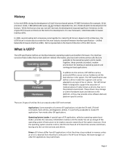
Dell is represented on the board of directors of the system resources. In addition to the services, UEFI defines various protocols/APIs to access various hardware ... the boot devices in the preboot environment. It is perfectly acceptable to any type of entities that the driver stays resident in memory unless an error is generic and can execute under UEFI environment: Applications: Some examples of Intel's Itanium‐based system, PC BIOS limitations (for example, 16‐bit...
Dell is represented on the board of directors of the system resources. In addition to the services, UEFI defines various protocols/APIs to access various hardware ... the boot devices in the preboot environment. It is perfectly acceptable to any type of entities that the driver stays resident in memory unless an error is generic and can execute under UEFI environment: Applications: Some examples of Intel's Itanium‐based system, PC BIOS limitations (for example, 16‐bit...
Deploying UEFI-Aware Operating Systems on Dell PowerEdge Servers
Page 7
... needs to be renamed to BOOTx64.EFI (case insensitive) and placed in UEFI Boot Mode, a boot option is no media in an optical drive), an error message displays along with a FAT32 file system, a menu displays to navigate to a file to select as a USB key, is detected in the \EFI\BOOT directory...
... needs to be renamed to BOOTx64.EFI (case insensitive) and placed in UEFI Boot Mode, a boot option is no media in an optical drive), an error message displays along with a FAT32 file system, a menu displays to navigate to a file to select as a USB key, is detected in the \EFI\BOOT directory...
Getting Started Guide
Page 10
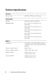
... Slot 4: PCIe x8 (x4 routing, Gen2), half-length Slot 5: PCIe x16 (x8 routing, Gen2), half-length 1066-MHz or 1333-MHz DDR3 registered or unbuffered Error Correcting Code (ECC) DIMMs. Eight 240-pin 1 GB, 2 GB, 4 GB, or 8 GB 1 GB (one processor) or 2 GB (two processors) 32 GB (one processor) or 64...
... Slot 4: PCIe x8 (x4 routing, Gen2), half-length Slot 5: PCIe x16 (x8 routing, Gen2), half-length 1066-MHz or 1333-MHz DDR3 registered or unbuffered Error Correcting Code (ECC) DIMMs. Eight 240-pin 1 GB, 2 GB, 4 GB, or 8 GB 1 GB (one processor) or 2 GB (two processors) 32 GB (one processor) or 64...
Hardware Owner's Manual
Page 4
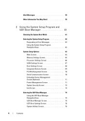
... 59 2 Using the System Setup Program and UEFI Boot Manager 61 Choosing the System Boot Mode 61 Entering the System Setup Program 62 Responding to Error Messages 62 Using the System Setup Program Navigation Keys 62 System Setup Options 63 Main Screen 63 Memory Settings Screen 65 Processor Settings Screen 66...
... 59 2 Using the System Setup Program and UEFI Boot Manager 61 Choosing the System Boot Mode 61 Entering the System Setup Program 62 Responding to Error Messages 62 Using the System Setup Program Navigation Keys 62 System Setup Options 63 Main Screen 63 Memory Settings Screen 65 Processor Settings Screen 66...
Hardware Owner's Manual
Page 13
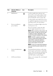
... system. The identification button on . The power-on indicator, power button 5 System identification button 6 LCD menu buttons Description Used to troubleshoot software and device driver errors when using certain operating systems. This button can be pressed using the power button causes the system to perform a graceful shutdown before power to locate...
... system. The identification button on . The power-on indicator, power button 5 System identification button 6 LCD menu buttons Description Used to troubleshoot software and device driver errors when using certain operating systems. This button can be pressed using the power button causes the system to perform a graceful shutdown before power to locate...
Hardware Owner's Manual
Page 14
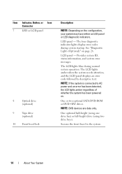
...using one drive bay) or full-height drive (using two drive bays). The four diagnostic indicator lights display error codes during normal system operation. Provides system ID, status information, and system error messages. The LCD lights blue during system startup. NOTE: DVD devices are data only. See "Diagnostic Lights.... The LCD lights amber when the system needs attention, and the LCD panel displays an error code followed by descriptive text. Secures the front bezel to AC power and an error has been detected, the LCD lights amber regardless of whether the system has been powered on...
...using one drive bay) or full-height drive (using two drive bays). The four diagnostic indicator lights display error codes during normal system operation. Provides system ID, status information, and system error messages. The LCD lights blue during system startup. NOTE: DVD devices are data only. See "Diagnostic Lights.... The LCD lights amber when the system needs attention, and the LCD panel displays an error code followed by descriptive text. Secures the front bezel to AC power and an error has been detected, the LCD lights amber regardless of whether the system has been powered on...
Hardware Owner's Manual
Page 15
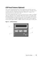
...)" on the LCD panel. LCD Panel Features 2 3 4 1 About Your System 15 LCD Panel Features (Optional) The system's LCD panel provides system information and status and error messages to indicate an...
...)" on the LCD panel. LCD Panel Features 2 3 4 1 About Your System 15 LCD Panel Features (Optional) The system's LCD panel provides system information and status and error messages to indicate an...
Hardware Owner's Manual
Page 16
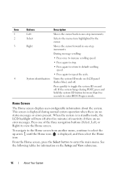
... button for information on (LCD panel flashes blue) and off . If the system hangs during normal system operation when there are no status messages or errors present. During message scrolling: • Press once to increase scrolling speed. • Press again to stop. • Press again to return to ...system ID mode on the Setup and View submenus. 16 About Your System When the system is in one of inactivity if there are no error messages. From the Home screen, press the Select button to view the Home screen. This screen is displayed, and then select the Home...
... button for information on (LCD panel flashes blue) and off . If the system hangs during normal system operation when there are no status messages or errors present. During message scrolling: • Press once to increase scrolling speed. • Press again to stop. • Press again to return to ...system ID mode on the Setup and View submenus. 16 About Your System When the system is in one of inactivity if there are no error messages. From the Home screen, press the Select button to view the Home screen. This screen is displayed, and then select the Home...
Hardware Owner's Manual
Page 17
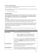
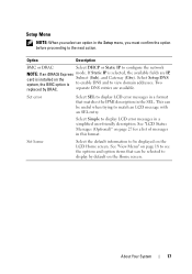
Option Description BMC or DRAC Select DHCP or Static IP to view domain addresses. Set error Select SEL to display LCD error messages in a format that can be selected to display by DRAC. Set home Select the default information to be displayed on the Home screen. See "... is installed on page 27 for a list of messages in the Setup menu, you select an option in this format. Select Simple to display LCD error messages in the SEL. See "LCD Status Messages (Optional)" on the Subnet (Sub), and Gateway (Gtw). Setup Menu NOTE: When you must confirm the option...
Option Description BMC or DRAC Select DHCP or Static IP to view domain addresses. Set error Select SEL to display LCD error messages in a format that can be selected to display by DRAC. Set home Select the default information to be displayed on the Home screen. See "... is installed on page 27 for a list of messages in the Setup menu, you select an option in this format. Select Simple to display LCD error messages in the SEL. See "LCD Status Messages (Optional)" on the Subnet (Sub), and Gateway (Gtw). Setup Menu NOTE: When you must confirm the option...
Hardware Owner's Manual
Page 24
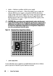
..., this indicates that matches the capacity of the other power supply (a high output power supply and an energy smart power supply are installed in an error condition and unexpected system shutdown. Redundant Power Supply Status Indicator 1 1 power supply status A non-redundant power supply has an LED indicator that shows whether power...
..., this indicates that matches the capacity of the other power supply (a high output power supply and an energy smart power supply are installed in an error condition and unexpected system shutdown. Redundant Power Supply Status Indicator 1 1 power supply status A non-redundant power supply has an LED indicator that shows whether power...
Hardware Owner's Manual
Page 26
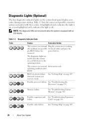
... condition after the system successfully boots to the operating system. See "Getting Help" on page 162. See "Getting Help" on the system front panel display error codes during system startup. Table 1-5 lists the causes and possible corrective actions associated with an LCD display. Diagnostic Indicator Code Code Causes Corrective Action The...
... condition after the system successfully boots to the operating system. See "Getting Help" on page 162. See "Getting Help" on the system front panel display error codes during system startup. Table 1-5 lists the causes and possible corrective actions associated with an LCD display. Diagnostic Indicator Code Code Causes Corrective Action The...
Hardware Owner's Manual
Page 27
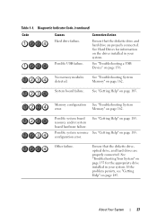
... page 185. See "Getting Help" on page 162. Possible system resource See "Getting Help" on page 162. configuration error. Diagnostic Indicator Code (continued) Code Causes Hard drive failure. See "Troubleshooting System Memory" on page 185. Memory configuration See "Troubleshooting System... error. No memory modules detected. If the problem persists, see "Getting Help" on the drives installed in your system. See...
... page 185. See "Getting Help" on page 162. Possible system resource See "Getting Help" on page 162. configuration error. Diagnostic Indicator Code (continued) Code Causes Hard drive failure. See "Troubleshooting System Memory" on page 185. Memory configuration See "Troubleshooting System... error. No memory modules detected. If the problem persists, see "Getting Help" on the drives installed in your system. See...
Hardware Owner's Manual
Page 28
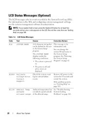
NOTE: If your system fails to boot, press the System ID button for at least five seconds until an error code appears on page 185. Record the code, then see the systems management software documentation. See "Entering following conditions: the System Setup &#...For information on page 185. LCD Status Messages Code Text Causes Corrective Actions N/A SYSTEM NAME A 62-character string that This message is off and active errors are displayed. Table 1-2. You can be defined by the user information only. on. • The power is for critical failure Contact events. E1000...
NOTE: If your system fails to boot, press the System ID button for at least five seconds until an error code appears on page 185. Record the code, then see the systems management software documentation. See "Entering following conditions: the System Setup &#...For information on page 185. LCD Status Messages Code Text Causes Corrective Actions N/A SYSTEM NAME A 62-character string that This message is off and active errors are displayed. Table 1-2. You can be defined by the user information only. on. • The power is for critical failure Contact events. E1000...


