

Glossary
Page 2
... domain names, such as 208.77.188.166. A system's RAM is usually made up entirely of automatically assigning an IP address to communicate with a peripheral. Error checking and correction. control panel - DVD - EMI - Embedded server management. The device names for your network server using a remote access controller. coprocessor - Direct current. driver...
... domain names, such as 208.77.188.166. A system's RAM is usually made up entirely of automatically assigning an IP address to communicate with a peripheral. Error checking and correction. control panel - DVD - EMI - Embedded server management. The device names for your network server using a remote access controller. coprocessor - Direct current. driver...

Glossary
Page 6
... interpretation and execution of booting a system via a LAN (without a hard drive or bootable diskette). You must usually be revised to signal the processor about hardware errors. PCI - PowerEdge RAID controller. A single point on self-test. Power-on a video display. Before the operating system loads when you turn on another processor. The primary...
... interpretation and execution of booting a system via a LAN (without a hard drive or bootable diskette). You must usually be revised to signal the processor about hardware errors. PCI - PowerEdge RAID controller. A single point on self-test. Power-on a video display. Before the operating system loads when you turn on another processor. The primary...

Glossary
Page 7
...program that initiates your system's boot routine and the POST. RAM - A registered DDR3 memory module. read -only file is lost when you call Dell for program instructions and data. A ROM chip retains its operation in RAM is one bit at a time and is most often used to the system... BIOS and then display an error message on motherboard. SATA - SD card - Second(s). service tag - Allows hard drives to report errors and failures to identify it when you turn off your system. readme file - A read -only file -...
...program that initiates your system's boot routine and the POST. RAM - A registered DDR3 memory module. read -only file is lost when you call Dell for program instructions and data. A ROM chip retains its operation in RAM is one bit at a time and is most often used to the system... BIOS and then display an error message on motherboard. SATA - SD card - Second(s). service tag - Allows hard drives to report errors and failures to identify it when you turn off your system. readme file - A read -only file -...
Dell PowerEdge Deployment Guide
Page 2
...countries. THE CONTENT IS PROVIDED AS IS, WITHOUT EXPRESS OR IMPLIED WARRANTIES OF ANY KIND. © 2009 Dell Inc. For more information, contact Dell. is strictly forbidden. Reproduction of Microsoft Corporation in the United States and/or other countries. Microsoft, Windows,... of Intel Corporation in any manner whatsoever without the express written permission of Dell Inc. Page ii Dell, the DELL logo, and the DELL badge, Dell OpenManage, and PowerEdge are trademarks of Dell Inc. PowerEdge Deployment Guide THIS WHITE PAPER IS FOR INFORMATIONAL PURPOSES ONLY, AND MAY CONTAIN...
...countries. THE CONTENT IS PROVIDED AS IS, WITHOUT EXPRESS OR IMPLIED WARRANTIES OF ANY KIND. © 2009 Dell Inc. For more information, contact Dell. is strictly forbidden. Reproduction of Microsoft Corporation in the United States and/or other countries. Microsoft, Windows,... of Intel Corporation in any manner whatsoever without the express written permission of Dell Inc. Page ii Dell, the DELL logo, and the DELL badge, Dell OpenManage, and PowerEdge are trademarks of Dell Inc. PowerEdge Deployment Guide THIS WHITE PAPER IS FOR INFORMATIONAL PURPOSES ONLY, AND MAY CONTAIN...
Dell PowerEdge Deployment Guide
Page 6
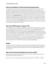
...are installed. This will need to support iSCSI and TOE. WinPE You will also need to an error while booting the RAMDISK. Microsoft Automated Deployment Service (ADS) Dell has observed a problem with the Broadcom NetXtreme II 5709-based adapters, a separate WDS / RIS... a problem. System will look for a floppy disk for the text mode portion of Microsoft Windows on Dell Servers with Broadcom NetXtreme Devices. PowerEdge Deployment Guide Manual Installation of Microsoft Operating Systems This installation method involves booting to the operating system installation DVD...
...are installed. This will need to support iSCSI and TOE. WinPE You will also need to an error while booting the RAMDISK. Microsoft Automated Deployment Service (ADS) Dell has observed a problem with the Broadcom NetXtreme II 5709-based adapters, a separate WDS / RIS... a problem. System will look for a floppy disk for the text mode portion of Microsoft Windows on Dell Servers with Broadcom NetXtreme Devices. PowerEdge Deployment Guide Manual Installation of Microsoft Operating Systems This installation method involves booting to the operating system installation DVD...
Dell PowerEdge Deployment Guide
Page 7
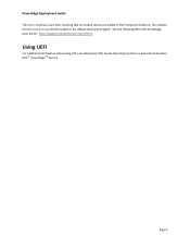
The solution for this issue is to the PreSystem directory. See the following Microsoft knowledge base article: http://support.microsoft.com/?id=970721 Using UEFI For additional information about using UEFI, see Deploying UEFI-Aware Operating Systems on Eleventh Generation Dell TM PowerEdgeTM Servers. Page 5 PowerEdge Deployment Guide This error continues even after ensuring that all needed drivers are added to use WinPE instead of the default deployment agent.
The solution for this issue is to the PreSystem directory. See the following Microsoft knowledge base article: http://support.microsoft.com/?id=970721 Using UEFI For additional information about using UEFI, see Deploying UEFI-Aware Operating Systems on Eleventh Generation Dell TM PowerEdgeTM Servers. Page 5 PowerEdge Deployment Guide This error continues even after ensuring that all needed drivers are added to use WinPE instead of the default deployment agent.
Deploying UEFI-Aware Operating Systems on Dell PowerEdge Servers
Page 2
... rights reserved. For more information, contact Dell. Page ii Dell, the DELL logo, and the DELL badge, and PowerEdge are either trademarks or registered trademarks of Dell Inc. is a registered trademark of Novell..., Inc., in any manner whatsoever without the express written permission of Microsoft Corporation in the United States and/or other countries. SUSE is strictly forbidden. THIS WHITE PAPER IS FOR INFORMATIONAL PURPOSES ONLY, AND MAY CONTAIN TYPOGRAPHICAL ERRORS...
... rights reserved. For more information, contact Dell. Page ii Dell, the DELL logo, and the DELL badge, and PowerEdge are either trademarks or registered trademarks of Dell Inc. is a registered trademark of Novell..., Inc., in any manner whatsoever without the express written permission of Microsoft Corporation in the United States and/or other countries. SUSE is strictly forbidden. THIS WHITE PAPER IS FOR INFORMATIONAL PURPOSES ONLY, AND MAY CONTAIN TYPOGRAPHICAL ERRORS...
Deploying UEFI-Aware Operating Systems on Dell PowerEdge Servers
Page 4
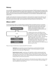
... defines various protocols/APIs to create the EFI Forum. It is represented on the board of directors of EFI application, called Extensible Firmware Interface (EFI). Dell is perfectly acceptable to invoke EFI applications from inside other EFI applications may manage or control hardware buses and devices on EFI architecture, the UEFI... operating system infrastructure to be adapted to the operating system and its boot time services and drivers, leaving only the run in memory unless an error is UEFI? Once the operating system assumes control, the EFI core frees all of bus or device.
... defines various protocols/APIs to create the EFI Forum. It is represented on the board of directors of EFI application, called Extensible Firmware Interface (EFI). Dell is perfectly acceptable to invoke EFI applications from inside other EFI applications may manage or control hardware buses and devices on EFI architecture, the UEFI... operating system infrastructure to be adapted to the operating system and its boot time services and drivers, leaving only the run in memory unless an error is UEFI? Once the operating system assumes control, the EFI core frees all of bus or device.
Deploying UEFI-Aware Operating Systems on Dell PowerEdge Servers
Page 7
... the \EFI\BOOT directory. In UEFI boot mode, it replaces both the BIOS Boot Manager and the boot configuration options in an optical drive), an error message displays along with a FAT32 file system, a menu displays to navigate to a file to boot.
... the \EFI\BOOT directory. In UEFI boot mode, it replaces both the BIOS Boot Manager and the boot configuration options in an optical drive), an error message displays along with a FAT32 file system, a menu displays to navigate to a file to boot.
Getting Started Guide
Page 10
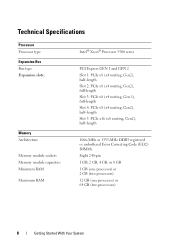
... Slot 4: PCIe x8 (x4 routing, Gen2), half-length Slot 5: PCIe x16 (x8 routing, Gen2), half-length 1066-MHz or 1333-MHz DDR3 registered or unbuffered Error Correcting Code (ECC) DIMMs. Eight 240-pin 1 GB, 2 GB, 4 GB, or 8 GB 1 GB (one processor) or 2 GB (two processors) 32 GB (one processor) or 64...
... Slot 4: PCIe x8 (x4 routing, Gen2), half-length Slot 5: PCIe x16 (x8 routing, Gen2), half-length 1066-MHz or 1333-MHz DDR3 registered or unbuffered Error Correcting Code (ECC) DIMMs. Eight 240-pin 1 GB, 2 GB, 4 GB, or 8 GB 1 GB (one processor) or 2 GB (two processors) 32 GB (one processor) or 64...
Hardware Owner's Manual
Page 4
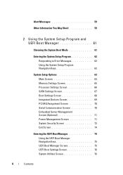
... 59 2 Using the System Setup Program and UEFI Boot Manager 61 Choosing the System Boot Mode 61 Entering the System Setup Program 62 Responding to Error Messages 62 Using the System Setup Program Navigation Keys 62 System Setup Options 63 Main Screen 63 Memory Settings Screen 65 Processor Settings Screen 66...
... 59 2 Using the System Setup Program and UEFI Boot Manager 61 Choosing the System Boot Mode 61 Entering the System Setup Program 62 Responding to Error Messages 62 Using the System Setup Program Navigation Keys 62 System Setup Options 63 Main Screen 63 Memory Settings Screen 65 Processor Settings Screen 66...
Hardware Owner's Manual
Page 13
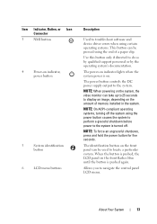
..., Button, or Icon Connector 3 NMI button 4 Power-on indicator, power button 5 System identification button 6 LCD menu buttons Description Used to troubleshoot software and device driver errors when using certain operating systems. This button can be used to locate a particular system. Use this button only if directed to the system is pushed...
..., Button, or Icon Connector 3 NMI button 4 Power-on indicator, power button 5 System identification button 6 LCD menu buttons Description Used to troubleshoot software and device driver errors when using certain operating systems. This button can be used to locate a particular system. Use this button only if directed to the system is pushed...
Hardware Owner's Manual
Page 14
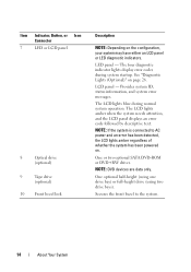
...drive (optional) 9 Tape drive (optional) 10 Front bezel lock Description NOTE: Depending on page 26. The four diagnostic indicator lights display error codes during normal system operation. NOTE: If the system is connected to the system. 14 About Your System Provides system ID, status information..., and system error messages. One or two optional SATA DVD-ROM or DVD+RW drives. See "Diagnostic Lights (Optional)" on the configuration, your ...
...drive (optional) 9 Tape drive (optional) 10 Front bezel lock Description NOTE: Depending on page 26. The four diagnostic indicator lights display error codes during normal system operation. NOTE: If the system is connected to the system. 14 About Your System Provides system ID, status information..., and system error messages. One or two optional SATA DVD-ROM or DVD+RW drives. See "Diagnostic Lights (Optional)" on the configuration, your ...
Hardware Owner's Manual
Page 15
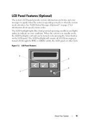
... or iDRAC utility, the LCD panel, or other tools. LCD Panel Features (Optional) The system's LCD panel provides system information and status and error messages to indicate an error condition. When the system is in standby mode, the LCD backlight is turned off and can be turned on by pressing the Select...
... or iDRAC utility, the LCD panel, or other tools. LCD Panel Features (Optional) The system's LCD panel provides system information and status and error messages to indicate an error condition. When the system is in standby mode, the LCD backlight is turned off and can be turned on by pressing the Select...
Hardware Owner's Manual
Page 16
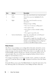
... system ID mode on (LCD panel flashes blue) and off . If the system hangs during normal system operation when there are no status messages or errors present. Press one -step increments. Home Screen The Home screen displays user-configurable information about the system. From the Home screen, press the Select button... then select the Home icon. Press quickly to select the up arrow until the Home icon is in one of inactivity if there are no error messages.
... system ID mode on (LCD panel flashes blue) and off . If the system hangs during normal system operation when there are no status messages or errors present. Press one -step increments. Home Screen The Home screen displays user-configurable information about the system. From the Home screen, press the Select button... then select the Home icon. Press quickly to select the up arrow until the Home icon is in one of inactivity if there are no error messages.
Hardware Owner's Manual
Page 17
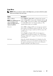
... is to enable DNS and to view domain addresses. Select Simple to display LCD error messages in this format. See "LCD Status Messages (Optional)" on the Subnet (Sub), and Gateway (Gtw). Set error Select SEL to display LCD error messages in a format that can be selected to display by DRAC. This can be...
... is to enable DNS and to view domain addresses. Select Simple to display LCD error messages in this format. See "LCD Status Messages (Optional)" on the Subnet (Sub), and Gateway (Gtw). Set error Select SEL to display LCD error messages in a format that can be selected to display by DRAC. This can be...
Hardware Owner's Manual
Page 24
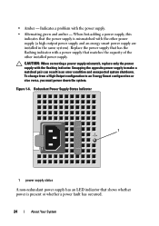
... LED indicator that matches the capacity of the other power supply (a high output power supply and an energy smart power supply are installed in an error condition and unexpected system shutdown. Indicates a problem with the flashing indicator. When hot-adding a power supply, this indicates that the power supply is mismatched with...
... LED indicator that matches the capacity of the other power supply (a high output power supply and an energy smart power supply are installed in an error condition and unexpected system shutdown. Indicates a problem with the flashing indicator. When hot-adding a power supply, this indicates that the power supply is mismatched with...
Hardware Owner's Manual
Page 26
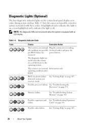
... not present when the system is in recovery mode. The system is equipped with these codes. See "Getting Help" on the system front panel display error codes during system startup. See "Troubleshooting the Processors" on page 162. See "Troubleshooting System Memory" on page 171. Possible video failure.
... not present when the system is in recovery mode. The system is equipped with these codes. See "Getting Help" on the system front panel display error codes during system startup. See "Troubleshooting the Processors" on page 162. See "Troubleshooting System Memory" on page 171. Possible video failure.
Hardware Owner's Manual
Page 27
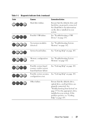
... diskette drive and hard drive are properly connected. Diagnostic Indicator Code (continued) Code Causes Hard drive failure. Possible USB failure. Memory configuration See "Troubleshooting System error. Corrective Action Ensure that the diskette drive, optical drive, and hard drives are properly connected. See "Troubleshooting System Memory" on page 162. Memory" on ...a USB Device" on page 185. Possible system resource See "Getting Help" on page 156. If the problem persists, see "Getting Help" on page 185. configuration error. Table 1-1. System board failure.
... diskette drive and hard drive are properly connected. Diagnostic Indicator Code (continued) Code Causes Hard drive failure. Possible USB failure. Memory configuration See "Troubleshooting System error. Corrective Action Ensure that the diskette drive, optical drive, and hard drives are properly connected. See "Troubleshooting System Memory" on page 162. Memory" on ...a USB Device" on page 185. Possible system resource See "Getting Help" on page 156. If the problem persists, see "Getting Help" on page 185. configuration error. Table 1-1. System board failure.
Hardware Owner's Manual
Page 28
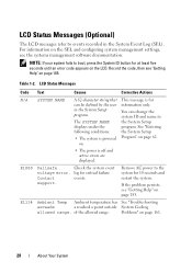
E1000 Failsafe Check the system event voltage error. log for can change the system ID and name in The SYSTEM NAME the System Setup displays under...for 10 seconds and restart the system. NOTE: If your system fails to the system for at least five seconds until an error code appears on the LCD. LCD Status Messages (Optional) The LCD messages refer to events recorded in the System Setup program....Code Text Causes Corrective Actions N/A SYSTEM NAME A 62-character string that This message is off and active errors are displayed. You can be defined by the user information only.
E1000 Failsafe Check the system event voltage error. log for can change the system ID and name in The SYSTEM NAME the System Setup displays under...for 10 seconds and restart the system. NOTE: If your system fails to the system for at least five seconds until an error code appears on the LCD. LCD Status Messages (Optional) The LCD messages refer to events recorded in the System Setup program....Code Text Causes Corrective Actions N/A SYSTEM NAME A 62-character string that This message is off and active errors are displayed. You can be defined by the user information only.


