Getting Started Guide
Page 6
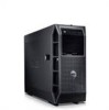
...an optional SAS controller card or backplane. Up to four internal, 3.5-inch, Serial-Attached SCSI (SAS) hard drives with an optional redundant 528-W power supply. The following resolutions: 640 x 480, 800 x 600, 1024 x 768, 1280 x 1024, and 1600 x 1200. • Systems ...drive bay for floppy drive. • Support for remote systems management. This option requires a dedicated PCI slot (slot #1). • A 490-W power supply. For more information about specific features, see "Using the System Setup Program" in the Hardware Owner's Manual. • Enhanced security features, including a...
...an optional SAS controller card or backplane. Up to four internal, 3.5-inch, Serial-Attached SCSI (SAS) hard drives with an optional redundant 528-W power supply. The following resolutions: 640 x 480, 800 x 600, 1024 x 768, 1280 x 1024, and 1600 x 1200. • Systems ...drive bay for floppy drive. • Support for remote systems management. This option requires a dedicated PCI slot (slot #1). • A 490-W power supply. For more information about specific features, see "Using the System Setup Program" in the Hardware Owner's Manual. • Enhanced security features, including a...

Getting Started Guide
Page 10
Connecting the Power Connect the system's power cable(s) to plug into a grounded electrical outlet or a separate power source such as an uninterrupted power supply (UPS) or a power distribution unit (PDU). 8 Getting Started With Your System The connectors on the monitor's cable connector. Connecting the Keyboard, Mouse, and Monitor Connect the keyboard, mouse, and monitor (optional). Plug the other end of your system have icons indicating which cable to the system. Be sure to tighten the screws (if any) on the back of the cable into each connector.
Connecting the Power Connect the system's power cable(s) to plug into a grounded electrical outlet or a separate power source such as an uninterrupted power supply (UPS) or a power distribution unit (PDU). 8 Getting Started With Your System The connectors on the monitor's cable connector. Connecting the Keyboard, Mouse, and Monitor Connect the keyboard, mouse, and monitor (optional). Plug the other end of your system have icons indicating which cable to the system. Be sure to tighten the screws (if any) on the back of the cable into each connector.
Getting Started Guide
Page 14
... Current consumption Heat dissipation Maximum inrush current System battery Physical Height Width Depth Weight Integrated ATI ES1000 VGA controller 32 MB 490 W 528 W (optional redundant power supply) 100-240 VAC, 50/60 Hz 8.0-4.5 A 2275 BTU/hr maximum Under typical line conditions and over the entire system ambient operating range, the inrush current...
... Current consumption Heat dissipation Maximum inrush current System battery Physical Height Width Depth Weight Integrated ATI ES1000 VGA controller 32 MB 490 W 528 W (optional redundant power supply) 100-240 VAC, 50/60 Hz 8.0-4.5 A 2275 BTU/hr maximum Under typical line conditions and over the entire system ambient operating range, the inrush current...

Hardware Owner's Manual (PDF)
Page 5
... Shroud 69 Removing the Processor Airflow Shroud. . . . . . 70 Installing the Processor Airflow Shroud 72 Redundant and Non-Redundant Power Supplies . . . . 72 Removing a Redundant Power Supply 73 Installing a Redundant Power Supply 75 Removing a Non-redundant Power Supply . . . . 75 Installing a Non-Redundant Power Supply. . . . . 77 Hard Drives 77 Removing a Hot-Pluggable Hard Drive 77 Installing a Hot-Pluggable Hard Drive 78 Removing a Cabled...
... Shroud 69 Removing the Processor Airflow Shroud. . . . . . 70 Installing the Processor Airflow Shroud 72 Redundant and Non-Redundant Power Supplies . . . . 72 Removing a Redundant Power Supply 73 Installing a Redundant Power Supply 75 Removing a Non-redundant Power Supply . . . . 75 Installing a Non-Redundant Power Supply. . . . . 77 Hard Drives 77 Removing a Hot-Pluggable Hard Drive 77 Installing a Hot-Pluggable Hard Drive 78 Removing a Cabled...

Hardware Owner's Manual (PDF)
Page 7
... the System Battery 120 Chassis Intrusion Switch 120 Removing the Chassis Intrusion Switch 120 Installing the Chassis Intrusion Switch 121 Power Supply Distribution Module 122 Removing the Power Supply Distribution Module . 122 Installing the Power Supply Distribution Module . 123 SAS Backplane 124 Removing the SAS Backplane 124 Installing the SAS Backplane 126 Control Panel (Service-only...
... the System Battery 120 Chassis Intrusion Switch 120 Removing the Chassis Intrusion Switch 120 Installing the Chassis Intrusion Switch 121 Power Supply Distribution Module 122 Removing the Power Supply Distribution Module . 122 Installing the Power Supply Distribution Module . 123 SAS Backplane 124 Removing the SAS Backplane 124 Installing the SAS Backplane 126 Control Panel (Service-only...
Hardware Owner's Manual (PDF)
Page 8
...138 Troubleshooting a USB Device 138 Troubleshooting a NIC 140 Troubleshooting a Wet System 141 Troubleshooting a Damaged System 142 Troubleshooting the System Battery 143 Troubleshooting Redundant Power Supplies . . . . . 143 Troubleshooting System Cooling Problems 145 Troubleshooting a Fan 145 Troubleshooting System Memory 146 Troubleshooting an Internal USB Memory Key . . ....or SAS RAID Controller. . . . 157 Troubleshooting Expansion Cards 159 Troubleshooting the Microprocessor 161 5 Running the System Diagnostics 163 Using Dell PowerEdge Diagnostics 163 8 Contents
...138 Troubleshooting a USB Device 138 Troubleshooting a NIC 140 Troubleshooting a Wet System 141 Troubleshooting a Damaged System 142 Troubleshooting the System Battery 143 Troubleshooting Redundant Power Supplies . . . . . 143 Troubleshooting System Cooling Problems 145 Troubleshooting a Fan 145 Troubleshooting System Memory 146 Troubleshooting an Internal USB Memory Key . . ....or SAS RAID Controller. . . . 157 Troubleshooting Expansion Cards 159 Troubleshooting the Microprocessor 161 5 Running the System Diagnostics 163 Using Dell PowerEdge Diagnostics 163 8 Contents

Hardware Owner's Manual (PDF)
Page 14
... pushed again. 14 About Your System Use this button only if directed to the system. The power button controls the DC power supply output to do so by qualified support personnel or by the operating system's documentation. The identification buttons on the back... Table 1-2. Front-Panel Components Item Component Icon 1 3.5-inch drive bay 2 lower 5.25-inch drive bay 3 upper 5.25-inch drive bay 4 power button 5 NMI button 6 System identification button Description Holds an optional diskette drive. If the system is not running an ACPI-compliant operating system, the...
... pushed again. 14 About Your System Use this button only if directed to the system. The power button controls the DC power supply output to do so by qualified support personnel or by the operating system's documentation. The identification buttons on the back... Table 1-2. Front-Panel Components Item Component Icon 1 3.5-inch drive bay 2 lower 5.25-inch drive bay 3 upper 5.25-inch drive bay 4 power button 5 NMI button 6 System identification button Description Holds an optional diskette drive. If the system is not running an ACPI-compliant operating system, the...

Hardware Owner's Manual (PDF)
Page 17
... documentation for information about enabling, disabling, and configuring I/O ports and connectors. Table 1-3 lists the power supply indicator codes. Power supply fault Amber indicates a problem with the power supply. The indicators on . Table 1-3. AC line status Green indicates that the power supply is operational. Redundant Power Supply Indicators Indicator Function Power supply status Green indicates that a valid AC source is present or whether...
... documentation for information about enabling, disabling, and configuring I/O ports and connectors. Table 1-3 lists the power supply indicator codes. Power supply fault Amber indicates a problem with the power supply. The indicators on . Table 1-3. AC line status Green indicates that the power supply is operational. Redundant Power Supply Indicators Indicator Function Power supply status Green indicates that a valid AC source is present or whether...

Hardware Owner's Manual (PDF)
Page 18
Figure 1-4. Redundant Power Supply Indicators 1 2 3 1 power supply status (DC out is operational) 3 AC line status (AC in is operational) 2 power supply fault NIC Indicator Codes Each NIC on the back panel has an indicator that provides information on network activity and link status (see Table 1-4. Figure 1-3. NIC Indicators 1 2 1 link indicator 18 About Your System 2 activity indicator For a list of NIC indicator codes, see Figure 1-4).
Figure 1-4. Redundant Power Supply Indicators 1 2 3 1 power supply status (DC out is operational) 3 AC line status (AC in is operational) 2 power supply fault NIC Indicator Codes Each NIC on the back panel has an indicator that provides information on network activity and link status (see Table 1-4. Figure 1-3. NIC Indicators 1 2 1 link indicator 18 About Your System 2 activity indicator For a list of NIC indicator codes, see Figure 1-4).

Hardware Owner's Manual (PDF)
Page 23
... "Troubleshooting Redundant Power Supplies" on page 143. specified power supply is available from the specified power supply; See "Troubleshooting Redundant Power Supplies" on page 143. About Your System 23 power supply. E1610 PS # Missing No power is improperly installed or faulty. See "Troubleshooting Redundant Power Supplies" on page 143. E1618 PS # Predictive Power supply voltage is unavailable, source for specified Check the AC power power supply is out...
... "Troubleshooting Redundant Power Supplies" on page 143. specified power supply is available from the specified power supply; See "Troubleshooting Redundant Power Supplies" on page 143. About Your System 23 power supply. E1610 PS # Missing No power is improperly installed or faulty. See "Troubleshooting Redundant Power Supplies" on page 143. E1618 PS # Predictive Power supply voltage is unavailable, source for specified Check the AC power power supply is out...
Hardware Owner's Manual (PDF)
Page 24
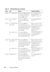
... D## F## PCI SERR Slot # The system BIOS has Remove and reseat the reported a PCI system error PCIe expansion cards. If Redundant Power the last supply fails, the Supplies" on page 175. page 159. E1711 PCI PERR B## D## F## PCI PERR Slot # The system BIOS has Remove and reseat the ...problem, see in the specified PCIe slot. Table 1-5. LCD Status Messages (continued) Code Text Causes Corrective Actions E1624 PS Redundancy The power supply subsystem See "Troubleshooting is unable to determine its origin. 24 About Your System If The system BIOS has reported a PCI system ...
... D## F## PCI SERR Slot # The system BIOS has Remove and reseat the reported a PCI system error PCIe expansion cards. If Redundant Power the last supply fails, the Supplies" on page 175. page 159. E1711 PCI PERR B## D## F## PCI PERR Slot # The system BIOS has Remove and reseat the ...problem, see in the specified PCIe slot. Table 1-5. LCD Status Messages (continued) Code Text Causes Corrective Actions E1624 PS Redundancy The power supply subsystem See "Troubleshooting is unable to determine its origin. 24 About Your System If The system BIOS has reported a PCI system ...
Hardware Owner's Manual (PDF)
Page 29
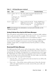
Replace RAID battery (see the "Glossary" on page 97). For example, if temperature for the system. • Power cycle - For other faults, you must take action to determine the problem if multiple related errors occur. Turn off Information only. For ...fault; You can often specify a very precise fault condition that sensor returns to the acceptable range, the message is a failing power supply. wait approximately ten seconds, reconnect the power cable, and restart the system. About Your System 29 Solving Problems Described by the RAC remote user. Removing LCD Status Messages ...
Replace RAID battery (see the "Glossary" on page 97). For example, if temperature for the system. • Power cycle - For other faults, you must take action to determine the problem if multiple related errors occur. Turn off Information only. For ...fault; You can often specify a very precise fault condition that sensor returns to the acceptable range, the message is a failing power supply. wait approximately ten seconds, reconnect the power cable, and restart the system. About Your System 29 Solving Problems Described by the RAC remote user. Removing LCD Status Messages ...
Hardware Owner's Manual (PDF)
Page 59
... how to install the following system components: • Front bezel • System cover • EMI fillers • Processor airflow shroud • Power supplies and power distribution board • Hard drives • Diskette drive • Optical and tape drives • Expansion cards • SAS controller card •...• System fan and expansion card fan • Memory • Processor • System battery • Chassis intrusion switch • power supply distribution module • SAS backplane • Control panel • System board Installing System Components 59
... how to install the following system components: • Front bezel • System cover • EMI fillers • Processor airflow shroud • Power supplies and power distribution board • Hard drives • Diskette drive • Optical and tape drives • Expansion cards • SAS controller card •...• System fan and expansion card fan • Memory • Processor • System battery • Chassis intrusion switch • power supply distribution module • SAS backplane • Control panel • System board Installing System Components 59

Hardware Owner's Manual (PDF)
Page 61
Figure 3-1. Inside View of the System 1 2 17 16 15 3 14 4 13 12 11 10 9 1 system cover 3 system fan 5 power distribution board shroud 7 processor and heat sink 9 control panel 5 6 8 7 2 processor airflow shroud 4 power supplies 6 system memory modules (6) 8 drive release latch 10 optical drive Installing System Components 61
Figure 3-1. Inside View of the System 1 2 17 16 15 3 14 4 13 12 11 10 9 1 system cover 3 system fan 5 power distribution board shroud 7 processor and heat sink 9 control panel 5 6 8 7 2 processor airflow shroud 4 power supplies 6 system memory modules (6) 8 drive release latch 10 optical drive Installing System Components 61

Hardware Owner's Manual (PDF)
Page 62
... the system board and internal peripherals through a pair of the system. Front Bezel The front bezel covers the front of redundant power supplies or a single non-redundant power supply. In order to four hot-pluggable hard drives. 11 5.25-inch drive bay 13 front bezel 15 3.5-inch hard drive bays (4) 17 expansion-card cover...
... the system board and internal peripherals through a pair of the system. Front Bezel The front bezel covers the front of redundant power supplies or a single non-redundant power supply. In order to four hot-pluggable hard drives. 11 5.25-inch drive bay 13 front bezel 15 3.5-inch hard drive bays (4) 17 expansion-card cover...

Hardware Owner's Manual (PDF)
Page 72
... installing redundant power supplies, see "Removing a Redundant Power Supply" on page 73 or "Installing a Redundant Power Supply" on your configuration, your system supports up to maximize efficiency. In redundant mode, the system distributes the power load across both power supplies to two hotpluggable redundant 528-W power supplies or a single non-redundant 490-W power supply. The second power supply provides power redundancy; Redundant and Non-Redundant Power Supplies Depending...
... installing redundant power supplies, see "Removing a Redundant Power Supply" on page 73 or "Installing a Redundant Power Supply" on your configuration, your system supports up to maximize efficiency. In redundant mode, the system distributes the power load across both power supplies to two hotpluggable redundant 528-W power supplies or a single non-redundant 490-W power supply. The second power supply provides power redundancy; Redundant and Non-Redundant Power Supplies Depending...

Hardware Owner's Manual (PDF)
Page 73
.... 4 Using the power supply handle, pull the power supply straight out of the chassis. Installing System Components 73 On power-redundant systems, remove and replace only one power supply at a time in toward the center of the power supply, then lift power supply handle to operate the system normally. Removing a Redundant Power Supply NOTICE: The system requires one power supply to release the power supply from the...
.... 4 Using the power supply handle, pull the power supply straight out of the chassis. Installing System Components 73 On power-redundant systems, remove and replace only one power supply at a time in toward the center of the power supply, then lift power supply handle to operate the system normally. Removing a Redundant Power Supply NOTICE: The system requires one power supply to release the power supply from the...

Hardware Owner's Manual (PDF)
Page 74
Removing and Installing a Redundant Power Supply 1 2 3 1 locking tab 3 cable retention bracket 2 power supply handle 74 Installing System Components Figure 3-9.
Removing and Installing a Redundant Power Supply 1 2 3 1 locking tab 3 cable retention bracket 2 power supply handle 74 Installing System Components Figure 3-9.

Hardware Owner's Manual (PDF)
Page 75
... Information Guide for the system to recognize the power supply and determine if it is functioning properly (see Figure 1-3). The power supply status indicator turns green if the power supply is functioning properly. 1 With the power supply handle in order to secure the power supply. 3 Connect the power cable to the power supply. 4 Route the power cable through the cable retention bracket (see Figure...
... Information Guide for the system to recognize the power supply and determine if it is functioning properly (see Figure 1-3). The power supply status indicator turns green if the power supply is functioning properly. 1 With the power supply handle in order to secure the power supply. 3 Connect the power cable to the power supply. 4 Route the power cable through the cable retention bracket (see Figure...

Hardware Owner's Manual (PDF)
Page 76
Removing and Installing a Non-redundant Power Supply 1 2 3 1 non-redundant power supply 3 screw 2 power supply release tab 76 Installing System Components Figure 3-10. 5 Remove the screw that secures the power supply to the system. 6 Press the power supply release tab and slide the power supply out of the system.
Removing and Installing a Non-redundant Power Supply 1 2 3 1 non-redundant power supply 3 screw 2 power supply release tab 76 Installing System Components Figure 3-10. 5 Remove the screw that secures the power supply to the system. 6 Press the power supply release tab and slide the power supply out of the system.


