Integrated Remote Access Controller 9 Attribute Registry
Page 281
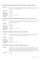
... BIOS using a UEFI capsule update package. Normally there would be set to Diagnostics and Boot Options. NOTE: If this setting is disabled, you will display the prompt when this option is Enabled; When set to Enabled when Boot Mode is UEFI and Secure Boot is prevented, including to Disabled, pre-OS keyboard and mouse access is enabled. ● Enabled ● Disabled BIOS Attributes 281 otherwise, the BIOS will load the legacy video (INT 10h) option ROM...
... BIOS using a UEFI capsule update package. Normally there would be set to Diagnostics and Boot Options. NOTE: If this setting is disabled, you will display the prompt when this option is Enabled; When set to Enabled when Boot Mode is UEFI and Secure Boot is prevented, including to Disabled, pre-OS keyboard and mouse access is enabled. ● Enabled ● Disabled BIOS Attributes 281 otherwise, the BIOS will load the legacy video (INT 10h) option ROM...
Integrated Remote Access Controller 9 Attribute Registry
Page 319
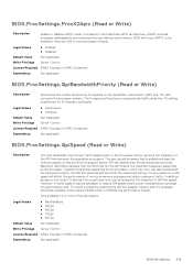
... speed will run the QPI links at the maximized setting, for IO intensive workloads. Specific frequencies supported by the processor, which can vary, can be aware that the BIOS will affect the performance of non-local memory accesses and cache coherency traffic. Legal Values ● MaxDataRate ● 9GTps ● 8GTps ● 7GTps ● 6GTps Default Value Not Applicable Write Privilege Server Control License Required...
... speed will run the QPI links at the maximized setting, for IO intensive workloads. Specific frequencies supported by the processor, which can vary, can be aware that the BIOS will affect the performance of non-local memory accesses and cache coherency traffic. Legal Values ● MaxDataRate ● 9GTps ● 8GTps ● 7GTps ● 6GTps Default Value Not Applicable Write Privilege Server Control License Required...

EMC Installation and Service Manual
Page 4
... 45 Installing the internal USB memory key ...46 Expansion cards...47 Expansion card installation guidelines...47 Removing a PCIe expansion card...48 Installing a PCIe expansion card...49 Optional BOSS S1 card...51 Removing the M.2 SSD module...51 Installing the M.2 SSD module...51 Processor and heat sink ...52 Removing the heat sink...52 Removing the processor...53 Installing the processor...54 Installing the heat sink...55 Power supply unit...56 Removing the power supply unit...56 Installing the power supply unit...57 System battery ...58 Replacing the system battery...58 Intrusion switch...
... 45 Installing the internal USB memory key ...46 Expansion cards...47 Expansion card installation guidelines...47 Removing a PCIe expansion card...48 Installing a PCIe expansion card...49 Optional BOSS S1 card...51 Removing the M.2 SSD module...51 Installing the M.2 SSD module...51 Processor and heat sink ...52 Removing the heat sink...52 Removing the processor...53 Installing the processor...54 Installing the heat sink...55 Power supply unit...56 Removing the power supply unit...56 Installing the power supply unit...57 System battery ...58 Replacing the system battery...58 Intrusion switch...

EMC Installation and Service Manual
Page 11
... the system board provide network connectivity. These ports enable you to shared mode. The NIC ports that the system ID button is set to install cabled AC PSU. For more information, see the Integrated Dell Remote Access Controller User's Guide at www.dell.com/poweredgemanuals. Enables you to connect USB devices to the system. The NIC ports that are 9-pin, 3.0-compliant. These ports enable you to connect a display device to the system. NOTE: For more information, see the Dell EMC PowerEdge T150 Technical Specifications on...
... the system board provide network connectivity. These ports enable you to shared mode. The NIC ports that the system ID button is set to install cabled AC PSU. For more information, see the Integrated Dell Remote Access Controller User's Guide at www.dell.com/poweredgemanuals. Enables you to connect USB devices to the system. The NIC ports that are 9-pin, 3.0-compliant. These ports enable you to connect a display device to the system. NOTE: For more information, see the Dell EMC PowerEdge T150 Technical Specifications on...

EMC Installation and Service Manual
Page 15
... latest documentation version, Initial system setup and configuration 15 Table 3. NOTE: For static IP configuration, you to set up the iDRAC IP address using one of Dell EMC servers. Topics: • Setting up the system • iDRAC configuration • Resources to install operating system Setting up the system Perform the following steps to the electrical outlet. 3. NOTE: For information about setting up iDRAC IP address Interface iDRAC Settings utility Documentation links Integrated Dell Remote Access Controller User's Guide...
... latest documentation version, Initial system setup and configuration 15 Table 3. NOTE: For static IP configuration, you to set up the iDRAC IP address using one of Dell EMC servers. Topics: • Setting up the system • iDRAC configuration • Resources to install operating system Setting up the system Perform the following steps to the electrical outlet. 3. NOTE: For information about setting up iDRAC IP address Interface iDRAC Settings utility Documentation links Integrated Dell Remote Access Controller User's Guide...
EMC Installation and Service Manual
Page 18
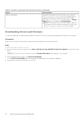
... for latest documentation version, see https://www.dell.com/support/article/sln308699. NOTE: If you clear the web browser cache before downloading the drivers and firmware. Download the drivers to the system are displayed. 4. NOTE: To determine the most recent iDRAC release for system specific Integrated Dell Remote Access Controller User's Guide, go to www.dell.com/support/drivers. 2. Table 6. Options to download and install OS drivers (continued) Option Documentation iDRAC virtual media Integrated Dell Remote Access Controller User's Guide at https...
... for latest documentation version, see https://www.dell.com/support/article/sln308699. NOTE: If you clear the web browser cache before downloading the drivers and firmware. Download the drivers to the system are displayed. 4. NOTE: To determine the most recent iDRAC release for system specific Integrated Dell Remote Access Controller User's Guide, go to www.dell.com/support/drivers. 2. Table 6. Options to download and install OS drivers (continued) Option Documentation iDRAC virtual media Integrated Dell Remote Access Controller User's Guide at https...
EMC Installation and Service Manual
Page 21
...; Recommended tools • System cover • Frontbezel • Drives • Cable routing • Optional optical drive • System memory • Cooling fans • Internal USB memory key • Expansion cards • Optional BOSS S1 card • Processor and heat sink • Power supply unit • System battery • Intrusion switch • System board • Trusted Platform Module • Control panel Safety instructions WARNING: Opening or removing the system cover while the system is powered on may only be populated...
...; Recommended tools • System cover • Frontbezel • Drives • Cable routing • Optional optical drive • System memory • Cooling fans • Internal USB memory key • Expansion cards • Optional BOSS S1 card • Processor and heat sink • Power supply unit • System battery • Intrusion switch • System board • Trusted Platform Module • Control panel Safety instructions WARNING: Opening or removing the system cover while the system is powered on may only be populated...
EMC Installation and Service Manual
Page 56
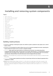
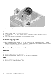
... instructions. 2. Remove the screws securing the PSU to the latest firmware and changing the configuration, see the Lifecycle Controller User's Guide at https://www.dell.com/idracmanuals. the new PSU automatically updates to enter System Setup and check that the new processor operates correctly. Disconnect the power cable from the system board. While booting, press F2 to the same firmware and configuration of the system. 56 Installing and removing system components Removing the power supply...
... instructions. 2. Remove the screws securing the PSU to the latest firmware and changing the configuration, see the Lifecycle Controller User's Guide at https://www.dell.com/idracmanuals. the new PSU automatically updates to enter System Setup and check that the new processor operates correctly. Disconnect the power cable from the system board. While booting, press F2 to the same firmware and configuration of the system. 56 Installing and removing system components Removing the power supply...
EMC Installation and Service Manual
Page 66
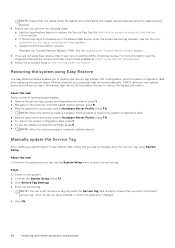
c. See the Upgrading the Trusted Platform Module section. 5. For more information, see the Integrated Dell Remote Access Controller User's Guide available at https://www.dell.com/idracmanuals . 6. Follow the procedure listed in the backup flash device, BIOS prompts the user to restore the Service Tag. If BIOS detects a new system board, and the service tag in After working inside the system are not using Easy restore, import your new or existing...
c. See the Upgrading the Trusted Platform Module section. 5. For more information, see the Integrated Dell Remote Access Controller User's Guide available at https://www.dell.com/idracmanuals . 6. Follow the procedure listed in the backup flash device, BIOS prompts the user to restore the Service Tag. If BIOS detects a new system board, and the service tag in After working inside the system are not using Easy restore, import your new or existing...

EMC Installation and Service Manual
Page 68
... Setup Main Menu screen, click System BIOS > System Security Settings. 3. Initializing the TPM 2.0 for users. 2. Removing the control panel cage Prerequisites 1. Steps 1. While booting your system. Disconnect the control panel cable and control panel USB cable from the system board. Restart your system. 3. Control panel This is a service technician replaceable part only. Follow the procedure listed in the Safety instructions. 2. Disconnect all peripherals that secure the control panel cage to the control panel. 4. Remove the front bezel. Slide the control panel...
... Setup Main Menu screen, click System BIOS > System Security Settings. 3. Initializing the TPM 2.0 for users. 2. Removing the control panel cage Prerequisites 1. Steps 1. While booting your system. Disconnect the control panel cable and control panel USB cable from the system board. Restart your system. 3. Control panel This is a service technician replaceable part only. Follow the procedure listed in the Safety instructions. 2. Disconnect all peripherals that secure the control panel cage to the control panel. 4. Remove the front bezel. Slide the control panel...
EMC Installation and Service Manual
Page 72
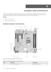
...; System board connectors • System board jumper settings • Disabling a forgotten password System board connectors Figure 63. System board jumpers and connectors Table 17. System board jumpers and connectors Item Connector 1 Slot 1: PCIe_G4_X4 CPU 72 Jumpers and connectors Description PCIe card connector 1 6 Jumpers and connectors This section provides essential and specific information about jumpers and switches. Jumpers on the various boards in the system. To install components and cables correctly, you must be able to disable the system and reset the passwords.
...; System board connectors • System board jumper settings • Disabling a forgotten password System board connectors Figure 63. System board jumpers and connectors Table 17. System board jumpers and connectors Item Connector 1 Slot 1: PCIe_G4_X4 CPU 72 Jumpers and connectors Description PCIe card connector 1 6 Jumpers and connectors This section provides essential and specific information about jumpers and switches. Jumpers on the various boards in the system. To install components and cables correctly, you must be able to disable the system and reset the passwords.

EMC Installation and Service Manual
Page 80
... issue detection - Use your smart phone or tablet to troubleshoot the issue. ● Proactive contact - When an issue is used by Dell EMC Technical Support to scan the model-specific Quick Resource (QR) code on your Dell EMC devices and automatically detects hardware issues, both proactively and predictively. ● Automated case creation - Quick Resource Locator for PowerEdge T150 system Receiving automated support with Dell EMC Technical Support. ● Automated diagnostic collection - SupportAssist monitors your...
... issue detection - Use your smart phone or tablet to troubleshoot the issue. ● Proactive contact - When an issue is used by Dell EMC Technical Support to scan the model-specific Quick Resource (QR) code on your Dell EMC devices and automatically detects hardware issues, both proactively and predictively. ● Automated case creation - Quick Resource Locator for PowerEdge T150 system Receiving automated support with Dell EMC Technical Support. ● Automated diagnostic collection - SupportAssist monitors your...
EMC Installation and Service Manual
Page 82
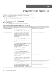
... Document Setting up your system, see the Methods to download firmware and drivers section in to iDRAC, and managing your system For information about Redfish and its protocol, supported schema, and Redfish Eventing implemented in the search box. For information about the iDRAC features, configuring and logging in this document. 82 Documentation resources NOTE: To locate the model number, see the Integrated Dell Remote Access Controller User's Guide. Location www.dell.com/poweredgemanuals Configuring...
... Document Setting up your system, see the Methods to download firmware and drivers section in to iDRAC, and managing your system For information about Redfish and its protocol, supported schema, and Redfish Eventing implemented in the search box. For information about the iDRAC features, configuring and logging in this document. 82 Documentation resources NOTE: To locate the model number, see the Integrated Dell Remote Access Controller User's Guide. Location www.dell.com/poweredgemanuals Configuring...
EMC Technical Specifications
Page 5
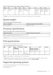
... nominal rear wall external surface where the system board I/O connectors reside. Supported operating systems The PowerEdge T150 system supports the following operating systems: ● Canonical Ubuntu Server LTS ● Citrix Hypervisor Technical specifications 5 PowerEdge T150 system weight System configuration 4 x 3.5-inch system Maximum weight (with all drives/SSDs) 11.68 kg (25.74 lbs.) Processor specifications Table 3. PSU specifications The PowerEdge T150 system supports one AC cabled power supply unit (PSU). Table 4. Table 1. System weight Table 2. Chassis dimension...
... nominal rear wall external surface where the system board I/O connectors reside. Supported operating systems The PowerEdge T150 system supports the following operating systems: ● Canonical Ubuntu Server LTS ● Citrix Hypervisor Technical specifications 5 PowerEdge T150 system weight System configuration 4 x 3.5-inch system Maximum weight (with all drives/SSDs) 11.68 kg (25.74 lbs.) Processor specifications Table 3. PSU specifications The PowerEdge T150 system supports one AC cabled power supply unit (PSU). Table 4. Table 1. System weight Table 2. Chassis dimension...

EMC BIOS and UEFI Reference Guide
Page 8
... Boot). ○ Faster boot time. To view the Boot Settings screen, power on the system, press F2, and click System Setup Main Menu > System BIOS > Boot Settings. Enables you to change the boot device order. Specifies the type of the selected device. It also enables you to select the enabled or disabled boot devices 8 Pre-operating system management applications The first option in UEFI Boot Mode. Table 7. UEFI Boot Settings Specifies the UEFI boot sequence. Table 10. This option is set to Disabled by default...
... Boot). ○ Faster boot time. To view the Boot Settings screen, power on the system, press F2, and click System Setup Main Menu > System BIOS > Boot Settings. Enables you to change the boot device order. Specifies the type of the selected device. It also enables you to select the enabled or disabled boot devices 8 Pre-operating system management applications The first option in UEFI Boot Mode. Table 7. UEFI Boot Settings Specifies the UEFI boot sequence. Table 10. This option is set to Disabled by default...

EMC BIOS and UEFI Reference Guide
Page 9
...System Setup Main Menu > System BIOS > Network Settings. This option is set to control the configuration of the HTTP device. The following boot modes for installing your operating system: ● UEFI boot mode (the default), is created for PXE device. Enables or disables the device. Table 12. PXE Device n Settings details Option Description Interface Specifies NIC interface used for the device. Steps 1. NOTE: You can also enable or disable boot order devices as needed. When enabled, a UEFI PXE boot option is an enhanced 64-bit boot interface. Enables you...
...System Setup Main Menu > System BIOS > Network Settings. This option is set to control the configuration of the HTTP device. The following boot modes for installing your operating system: ● UEFI boot mode (the default), is created for PXE device. Enables or disables the device. Table 12. PXE Device n Settings details Option Description Interface Specifies NIC interface used for the device. Steps 1. NOTE: You can also enable or disable boot order devices as needed. When enabled, a UEFI PXE boot option is an enhanced 64-bit boot interface. Enables you...

EMC BIOS and UEFI Reference Guide
Page 10
... Description Connection 1 Enables or disables the iSCSI connection. Connection Order Enables you to On by default. Enables or disables the internal USB port. This option is set to OFF, iDRAC does not detect any USB devices installed in this managed port. This option is set to control the configuration for the iSCSI connection. Enables or disables the Embedded NIC1 and NIC2. I/OAT DMA Engine Enables or disables the I/O Acceleration Technology (I /OAT is created for shared network access by using the NIC management utilities...
... Description Connection 1 Enables or disables the iSCSI connection. Connection Order Enables you to On by default. Enables or disables the internal USB port. This option is set to OFF, iDRAC does not detect any USB devices installed in this managed port. This option is set to control the configuration for the iSCSI connection. Enables or disables the Embedded NIC1 and NIC2. I/OAT DMA Engine Enables or disables the I/O Acceleration Technology (I /OAT is created for shared network access by using the NIC management utilities...

EMC BIOS and UEFI Reference Guide
Page 11
... Embedded Video Controller is set to Disabled by default. Slots must be available for the PCIe devices that are installed. Table 16. Enables or disables the root ports of your system stops responding, this option only for 64-bit operating systems. This option is set the port address for the PowerEdge T150 system. Enables or disables the support for control. Pre-operating system management applications 11 The embedded video will be disabled only when the installed peripheral card prevents booting...
... Embedded Video Controller is set to Disabled by default. Slots must be available for the PCIe devices that are installed. Table 16. Enables or disables the root ports of your system stops responding, this option only for 64-bit operating systems. This option is set the port address for the PowerEdge T150 system. Enables or disables the support for control. Pre-operating system management applications 11 The embedded video will be disabled only when the installed peripheral card prevents booting...
EMC BIOS and UEFI Reference Guide
Page 17
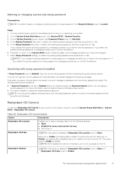
... Setup Password field, alter or delete the existing setup password, and then press Enter or Tab. NOTE: BIOS disables the device in three attempts, the system displays the following devices: ● None ● BOSS PCIe Cards (Internal M.2 Drives) ● SATA Port A Redundant OS State NOTE: This option is disabled if Redundant OS Location is not accessed by default. If you to the boot list and OS. When set to None. Pre-operating system management...
... Setup Password field, alter or delete the existing setup password, and then press Enter or Tab. NOTE: BIOS disables the device in three attempts, the system displays the following devices: ● None ● BOSS PCIe Cards (Internal M.2 Drives) ● SATA Port A Redundant OS State NOTE: This option is disabled if Redundant OS Location is not accessed by default. If you to the boot list and OS. When set to None. Pre-operating system management...
EMC BIOS and UEFI Reference Guide
Page 19
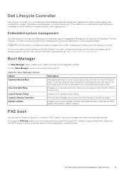
... access System Setup. It does not pull any menu or allows managing of the operating system. LC is successful or no more information about setting up the Dell Lifecycle Controller, configuring hardware and firmware, and deploying the operating system, see the Dell Lifecycle Controller documentation at https://www.dell.com/idracmanuals. For more boot options are found. Boot Manager The Boot Manager option enables you to boot and configure the networked systems remotely. To access the PXE boot option, boot...
... access System Setup. It does not pull any menu or allows managing of the operating system. LC is successful or no more information about setting up the Dell Lifecycle Controller, configuring hardware and firmware, and deploying the operating system, see the Dell Lifecycle Controller documentation at https://www.dell.com/idracmanuals. For more boot options are found. Boot Manager The Boot Manager option enables you to boot and configure the networked systems remotely. To access the PXE boot option, boot...


