
Getting Started Guide
Page 10
Technical Specifications Processor Processor type Expansion Bus Bus type Expansion slots Memory Architecture Memory module sockets Memory module capacities Minimum RAM Maximum RAM Drives Hard drives Optical drive Tape drive One Intel Xeon processor E3-1200 product family or One Intel Core ...
Technical Specifications Processor Processor type Expansion Bus Bus type Expansion slots Memory Architecture Memory module sockets Memory module capacities Minimum RAM Maximum RAM Drives Hard drives Optical drive Tape drive One Intel Xeon processor E3-1200 product family or One Intel Core ...

Getting Started Guide
Page 11
..., DTE, 16550-compatible Four 4-pin, USB 2.0-compliant 15-pin VGA One 7-pin connector Two 4-pin, USB 2.0-compliant Two 4-pin, USB 2.0-compliant Video Video type Video memory Matrox G200, integrated in Winbond WPCM450 8 MB Power AC power supply (per power supply) Wattage 305 W Voltage 100 VAC-240 VAC, 50 Hz/60 Hz...
..., DTE, 16550-compatible Four 4-pin, USB 2.0-compliant 15-pin VGA One 7-pin connector Two 4-pin, USB 2.0-compliant Two 4-pin, USB 2.0-compliant Video Video type Video memory Matrox G200, integrated in Winbond WPCM450 8 MB Power AC power supply (per power supply) Wattage 305 W Voltage 100 VAC-240 VAC, 50 Hz/60 Hz...
Owner's Manual
Page 4
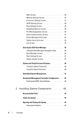
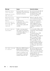
Main Screen 25 Memory Settings Screen 27 Processor Settings Screen 27 SATA Settings Screen 28 Boot Settings Screen 29 Integrated Devices Screen 29 PCI IRQ Assignments Screen 30 Serial ...
Main Screen 25 Memory Settings Screen 27 Processor Settings Screen 27 SATA Settings Screen 28 Boot Settings Screen 29 Integrated Devices Screen 29 PCI IRQ Assignments Screen 30 Serial ...

Owner's Manual
Page 6
... Expansion Card 69 Installing an Expansion Card 71 SAS Controller Expansion Card 72 System Memory 73 General Memory Module Installation Guidelines . . . 73 Mode-Specific Guidelines 73 Removing Memory Modules 75 Installing Memory Modules 76 Processor 78 Removing the Processor 78 Installing a Processor 81 Cooling Fan...84 Replacing the System Battery 84 Power Supply 86 Removing the Power Supply 86 Installing the Power Supply 87 Internal USB Memory Key 88 Chassis Intrusion Switch 89 Removing the Chassis Intrusion Switch 89 Installing the Chassis Intrusion Switch 90 Control Panel ...
... Expansion Card 69 Installing an Expansion Card 71 SAS Controller Expansion Card 72 System Memory 73 General Memory Module Installation Guidelines . . . 73 Mode-Specific Guidelines 73 Removing Memory Modules 75 Installing Memory Modules 76 Processor 78 Removing the Processor 78 Installing a Processor 81 Cooling Fan...84 Replacing the System Battery 84 Power Supply 86 Removing the Power Supply 86 Installing the Power Supply 87 Internal USB Memory Key 88 Chassis Intrusion Switch 89 Removing the Chassis Intrusion Switch 89 Installing the Chassis Intrusion Switch 90 Control Panel ...

Owner's Manual
Page 7
... 102 Troubleshooting a Damaged System 103 Troubleshooting the System Battery 104 Troubleshooting Power Supply 105 Troubleshooting System Cooling Problems 105 Troubleshooting Cooling Fan 106 Troubleshooting System Memory 107 Troubleshooting an Internal USB Key 108 Troubleshooting an Optical Drive 109 Troubleshooting a Tape Backup Unit 110 Contents 7
... 102 Troubleshooting a Damaged System 103 Troubleshooting the System Battery 104 Troubleshooting Power Supply 105 Troubleshooting System Cooling Problems 105 Troubleshooting Cooling Fan 106 Troubleshooting System Memory 107 Troubleshooting an Internal USB Key 108 Troubleshooting an Optical Drive 109 Troubleshooting a Tape Backup Unit 110 Contents 7

Owner's Manual
Page 10
... perform a graceful shutdown before power to the system. The power button controls the DC power supply output to the system is on the amount of memory installed in the system. NOTE: When powering on the system, the video monitor can take from several seconds to over 2 minutes to display an image...
... perform a graceful shutdown before power to the system. The power button controls the DC power supply output to the system is on the amount of memory installed in the system. NOTE: When powering on the system, the video monitor can take from several seconds to over 2 minutes to display an image...

Owner's Manual
Page 15
...Possible expansion card See "Troubleshooting Expansion failure. Possible video failure. Table 1-1. occurred. BIOS checksum failure detected; The diagnostic lights are not lit after POST. Memory failure. Cards" on page 113. The system is on; A highlighted circle indicates the light is in a normal Information only. a non-highlighted circle indicates...Getting Help" on page 107. operating condition after the system successfully boots to the operating system. Possible processor failure. See "Troubleshooting System Memory" on page 123. About Your System 15
...Possible expansion card See "Troubleshooting Expansion failure. Possible video failure. Table 1-1. occurred. BIOS checksum failure detected; The diagnostic lights are not lit after POST. Memory failure. Cards" on page 113. The system is on; A highlighted circle indicates the light is in a normal Information only. a non-highlighted circle indicates...Getting Help" on page 107. operating condition after the system successfully boots to the operating system. Possible processor failure. See "Troubleshooting System Memory" on page 123. About Your System 15

Owner's Manual
Page 16
..."Hard Drives" on page 56 for the appropriate drive installed in your system. See "Getting Help" on page 123. 16 About Your System Memory configuration See "Troubleshooting System error. Other failure. System board failure. See "Getting Help" on page 100. Possible system board resource and/or... system resource configuration error. Code Causes Hard drive failure. See "Troubleshooting a USB Device" on page 123. See "Troubleshooting System Memory" on the drives installed in your system. See "Troubleshooting Your System" on page 99 for information on page 107.
..."Hard Drives" on page 56 for the appropriate drive installed in your system. See "Getting Help" on page 123. 16 About Your System Memory configuration See "Troubleshooting System error. Other failure. System board failure. See "Getting Help" on page 100. Possible system board resource and/or... system resource configuration error. Code Causes Hard drive failure. See "Troubleshooting a USB Device" on page 123. See "Troubleshooting System Memory" on the drives installed in your system. See "Troubleshooting Your System" on page 99 for information on page 107.
Owner's Manual
Page 18
... may be reduced. PCI BIOS failed to expansion card loose; Invalid memory configuration. Reseat the expansion card. Manufacturing mode detected. The system will run but with less memory than is in a valid configuration. Faulty or missing optical drive subsystem, hard drive, or ...hard-drive subsystem, or no bootable USB key installed. Reboot to the expansion card. See "General Memory Module Installation Guidelines" on page 100. No boot device available. "Troubleshooting a USB Device" on page 73. Use a bootable USB key...
... may be reduced. PCI BIOS failed to expansion card loose; Invalid memory configuration. Reseat the expansion card. Manufacturing mode detected. The system will run but with less memory than is in a valid configuration. Faulty or missing optical drive subsystem, hard drive, or ...hard-drive subsystem, or no bootable USB key installed. Reboot to the expansion card. See "General Memory Module Installation Guidelines" on page 100. No boot device available. "Troubleshooting a USB Device" on page 73. Use a bootable USB key...

Owner's Manual
Page 19
... page 23. specified SATA port is no device connected Information only. faulty system SETUP program. SATA port x device configuration error. Memory has been added or removed or a memory module may be ignored. See "Using the System Setup Program and Boot Manager" on page 112. The drive connected to the ... the specified slot number. Reseat the PCIe card in the specified slot. SATA port x device autosensing error. SATA port x device error. If memory has not been added or removed, check the SEL to determine if single-bit or multi-bit errors were detected and replace the faulty...
... page 23. specified SATA port is no device connected Information only. faulty system SETUP program. SATA port x device configuration error. Memory has been added or removed or a memory module may be ignored. See "Using the System Setup Program and Boot Manager" on page 112. The drive connected to the ... the specified slot number. Reseat the PCIe card in the specified slot. SATA port x device autosensing error. SATA port x device error. If memory has not been added or removed, check the SEL to determine if single-bit or multi-bit errors were detected and replace the faulty...

Owner's Manual
Page 24
... the message. Down arrow or Moves to the previous field. Responding to finish booting, and then restart your system and try again. NOTE: After installing a memory upgrade, it is booting, make are recorded but do not take effect until you restart the system. 24 Using the System Setup Program and Boot...
... the message. Down arrow or Moves to the previous field. Responding to finish booting, and then restart your system and try again. NOTE: After installing a memory upgrade, it is booting, make are recorded but do not take effect until you restart the system. 24 Using the System Setup Program and Boot...

Owner's Manual
Page 25
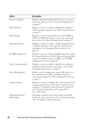
Displays information related to installed memory. See "Memory Settings Screen" on the system's internal calendar. Using the System Setup Program and Boot Manager 25 Sets the date on page 27. Option System Time System Date Memory Settings Description Sets the time on the system configuration. System Setup Options Main Screen NOTE: The options for the System Setup program change based on the system's internal clock. NOTE: The System Setup program defaults are listed under their respective options in the following sections, where applicable.
Displays information related to installed memory. See "Memory Settings Screen" on the system's internal calendar. Using the System Setup Program and Boot Manager 25 Sets the date on page 27. Option System Time System Date Memory Settings Description Sets the time on the system configuration. System Setup Options Main Screen NOTE: The options for the System Setup program change based on the system's internal clock. NOTE: The System Setup program defaults are listed under their respective options in the following sections, where applicable.
Owner's Manual
Page 26
... Assignments Screen" on page 31. Displays a screen to specify related features and options. For BIOS boot mode, you to each of the processor, fans, and memory modules with the NumLock mode activated on page 29. See "Serial Communication Screen" on page 30. Displays a screen to change the IRQ assigned to manage...
... Assignments Screen" on page 31. Displays a screen to specify related features and options. For BIOS boot mode, you to each of the processor, fans, and memory modules with the NumLock mode activated on page 29. See "Serial Communication Screen" on page 30. Displays a screen to change the IRQ assigned to manage...

Owner's Manual
Page 27
...a keyboard is attached to the system. Memory Settings Screen Option System Memory Size System Memory Type System Memory Speed Video Memory System Memory Testing (Enabled default) Description Displays the amount of system memory. Displays the system memory speed. Specifies whether system memory tests are displayed and logged in the ...and Disabled. Displays the processor bus speed. Using the System Setup Program and Boot Manager 27 Displays the type of system memory. Option Report Keyboard Errors (Report default) F1/F2 Prompt on errors during POST, which allows the user to observe events...
...a keyboard is attached to the system. Memory Settings Screen Option System Memory Size System Memory Type System Memory Speed Video Memory System Memory Testing (Enabled default) Description Displays the amount of system memory. Displays the system memory speed. Specifies whether system memory tests are displayed and logged in the ...and Disabled. Displays the processor bus speed. Using the System Setup Program and Boot Manager 27 Displays the type of system memory. Option Report Keyboard Errors (Report default) F1/F2 Prompt on errors during POST, which allows the user to observe events...

Owner's Manual
Page 28
... the BIOS. Stepping Level 2 Cache Displays the level 2 cache size. NOTE: Disable this field is enabled. Execute Disable (Enabled default) Enables or disables Execute Disable Memory Protection Technology. Logical Processor (Enabled default) On processors that support Simultaneous MultiThreading (SMT) technology, each processor is set to SATA port B. Virtualization Technology (Disabled default...
... the BIOS. Stepping Level 2 Cache Displays the level 2 cache size. NOTE: Disable this field is enabled. Execute Disable (Enabled default) Enables or disables Execute Disable Memory Protection Technology. Logical Processor (Enabled default) On processors that support Simultaneous MultiThreading (SMT) technology, each processor is set to SATA port B. Virtualization Technology (Disabled default...

Owner's Manual
Page 32
...screen as follows: • OS Control sets the CPU power to OS DBPM, the fan power to Minimum Power, and the memory power to Maximum Performance. Options are Maximum Performance or Minimum Power. For all but the Custom setting, the BIOS pre-configures ... and Boot Manager Power Management Screen Option Power Management (OS Control default) CPU Power and Performance Management Fan Power and Performance Management Memory Power and Performance Management Description Options are OS DBPM, Maximum Performance, or Minimum Power. The operating system sets the processor performance based...
...screen as follows: • OS Control sets the CPU power to OS DBPM, the fan power to Minimum Power, and the memory power to Maximum Performance. Options are Maximum Performance or Minimum Power. For all but the Custom setting, the BIOS pre-configures ... and Boot Manager Power Management Screen Option Power Management (OS Control default) CPU Power and Performance Management Fan Power and Performance Management Memory Power and Performance Management Description Options are OS DBPM, Maximum Performance, or Minimum Power. The operating system sets the processor performance based...

Owner's Manual
Page 41
...program and select the System Security. 2 Highlight Setup Password, press to validate the memory, I/O devices, processor, physical disks, and other peripherals Using the System Setup Program and Boot Manager 41 The Dell USC can be started during the boot sequence and can assign a system password. ... support the full set of the operating system. You cannot disable or change an existing system password. Embedded System Management The Dell USC is an embedded utility that enables systems and storage management tasks from unauthorized changes. Press twice to clear the existing setup...
...program and select the System Security. 2 Highlight Setup Password, press to validate the memory, I/O devices, processor, physical disks, and other peripherals Using the System Setup Program and Boot Manager 41 The Dell USC can be started during the boot sequence and can assign a system password. ... support the full set of the operating system. You cannot disable or change an existing system password. Embedded System Management The Dell USC is an embedded utility that enables systems and storage management tasks from unauthorized changes. Press twice to clear the existing setup...

Owner's Manual
Page 66
Read and follow the safety instructions that is not authorized by Dell is not covered by your warranty. WARNING: The memory modules and heat sink can develop quickly, resulting in your system with the product. 1 Turn off the system and attached peripherals. ...touch them. Overheating of the system. See Figure 3-15. 66 Installing System Components Cooling Shroud The cooling shroud directs airflow over the system processor and memory modules. See "Removing the Expansion-Card Stabilizer" on page 65. 4 Hold the touch points on page 45. 3 Remove the expansion-card stabilizer...
Read and follow the safety instructions that is not authorized by Dell is not covered by your warranty. WARNING: The memory modules and heat sink can develop quickly, resulting in your system with the product. 1 Turn off the system and attached peripherals. ...touch them. Overheating of the system. See Figure 3-15. 66 Installing System Components Cooling Shroud The cooling shroud directs airflow over the system processor and memory modules. See "Removing the Expansion-Card Stabilizer" on page 65. 4 Hold the touch points on page 45. 3 Remove the expansion-card stabilizer...

Owner's Manual
Page 73
... configurations, nor do they operate at the speed of each two-socket set is organized into two channels. The system contains four memory sockets, each channel is also supported in the numeric order of the sockets beginning with DIMM_A1 or DIMM_B1. • One or two DIMMs per ...channel can support up to observe these guidelines can prevent your system memory. Single and dual-rank DIMMs can be 1066 or 1333 MHz. Mode-Specific Guidelines Your system supports both single-channel and dual-channel mode. ...
... configurations, nor do they operate at the speed of each two-socket set is organized into two channels. The system contains four memory sockets, each channel is also supported in the numeric order of the sockets beginning with DIMM_A1 or DIMM_B1. • One or two DIMMs per ...channel can support up to observe these guidelines can prevent your system memory. Single and dual-rank DIMMs can be 1066 or 1333 MHz. Mode-Specific Guidelines Your system supports both single-channel and dual-channel mode. ...

Owner's Manual
Page 74
Table 3-2. Sample UDIMM Memory Configurations Memory Module Size 1 Memory Sockets 2 1 GB 2 GB 4 GB 8 GB 3 4 X X X X X X X X X X X X X X X X X X X X X X X X X X X X Single Processor Physical Memory (GB) 1 2 4 2 4 8 4 8 16 8 16 32 74 Installing System Components
Table 3-2. Sample UDIMM Memory Configurations Memory Module Size 1 Memory Sockets 2 1 GB 2 GB 4 GB 8 GB 3 4 X X X X X X X X X X X X X X X X X X X X X X X X X X X X Single Processor Physical Memory (GB) 1 2 4 2 4 8 4 8 16 8 16 32 74 Installing System Components


