
Rack Installation Guide
Page 26
... the cable-management arm and insert the LED end into the slot on the end of the cable-management arm. 3 Attach the I/O cable connectors and power cable connectors to its connector on the system back panel. Routing Cables on the Cable-Management Arm 1 2 3 back of system 4 5 6 7 1 cable-management... system status-indicator cable to their respective connectors on the system back panel. NOTE: Use the strain-relief loops on the back of the power supplies to be routed within the arms (see your system's Getting Started Guide or Hardware Owner's Manual. Figure 1-14. For details on cable ...
... the cable-management arm and insert the LED end into the slot on the end of the cable-management arm. 3 Attach the I/O cable connectors and power cable connectors to its connector on the system back panel. Routing Cables on the Cable-Management Arm 1 2 3 back of system 4 5 6 7 1 cable-management... system status-indicator cable to their respective connectors on the system back panel. NOTE: Use the strain-relief loops on the back of the power supplies to be routed within the arms (see your system's Getting Started Guide or Hardware Owner's Manual. Figure 1-14. For details on cable ...

Getting Started Guide
Page 5
...: - This optional SAS controller also supports RAID levels 0 and 1.) • An optional slimline IDE optical drive. • An optional external USB diskette drive. • A 600-W power supply. • Four dual-rotor fan modules. System Features The major hardware and software features of your system include: • One or two dual-core AMD...
...: - This optional SAS controller also supports RAID levels 0 and 1.) • An optional slimline IDE optical drive. • An optional external USB diskette drive. • A 600-W power supply. • Four dual-rotor fan modules. System Features The major hardware and software features of your system include: • One or two dual-core AMD...

Getting Started Guide
Page 9
Getting Started With Your System 7 Plug the other end of the power cable into a loop as an uninterruptible power supply (UPS) or a power distribution unit (PDU). Routing the Power Cable through the Power Cable Retention Bracket Bend the system power cable into a grounded electrical outlet or a separate power source such as shown in the illustration and secure the cable using the cable retention bracket. Connecting the Power Connect the system's power cable to the system.
Getting Started With Your System 7 Plug the other end of the power cable into a loop as an uninterruptible power supply (UPS) or a power distribution unit (PDU). Routing the Power Cable through the Power Cable Retention Bracket Bend the system power cable into a grounded electrical outlet or a separate power source such as shown in the illustration and secure the cable using the cable retention bracket. Connecting the Power Connect the system's power cable to the system.
Getting Started Guide
Page 12
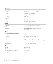
Connectors Back Panel NIC Serial USB Video Front Panel Video USB Video Video type Video memory Resolution Power AC power supply (per power supply for two integrated 1-GB NICs) 9-pin, DTE, 16550-compatible Two 4-pin, USB 2.0 compliant 15-pin VGA 15-pin VGA Two 4-pin...A 1462 BTU/hr (maximum) Under typical line conditions and over the entire system ambient operating range, the inrush current may reach 55 A per power supply) Wattage Voltage Heat dissipation Maximum inrush current System battery Physical Height Width Depth (including optional bezel) Weight (maximum configuration) Two RJ-45 (for ...
Connectors Back Panel NIC Serial USB Video Front Panel Video USB Video Video type Video memory Resolution Power AC power supply (per power supply for two integrated 1-GB NICs) 9-pin, DTE, 16550-compatible Two 4-pin, USB 2.0 compliant 15-pin VGA 15-pin VGA Two 4-pin...A 1462 BTU/hr (maximum) Under typical line conditions and over the entire system ambient operating range, the inrush current may reach 55 A per power supply) Wattage Voltage Heat dissipation Maximum inrush current System battery Physical Height Width Depth (including optional bezel) Weight (maximum configuration) Two RJ-45 (for ...
Hardware Owner's Manual
Page 4
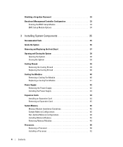
... Cooling Shroud 39 Replacing the Cooling Shroud 40 Cooling Fan Modules 40 Removing a Cooling Fan Module 40 Replacing a Cooling Fan Module 41 Power Supply 42 Removing the Power Supply 42 Installing the Power Supply 43 Expansion Cards 44 Installing an Expansion Card 44 Removing an Expansion Card 45 System Memory 46 Memory Module Installation Guidelines 46...
... Cooling Shroud 39 Replacing the Cooling Shroud 40 Cooling Fan Modules 40 Removing a Cooling Fan Module 40 Replacing a Cooling Fan Module 41 Power Supply 42 Removing the Power Supply 42 Installing the Power Supply 43 Expansion Cards 44 Installing an Expansion Card 44 Removing an Expansion Card 45 System Memory 46 Memory Module Installation Guidelines 46...

Hardware Owner's Manual
Page 6
... Battery 74 Troubleshooting the Power Supply 74 Troubleshooting System Cooling Problems 75 Troubleshooting a Fan 75 Troubleshooting System Memory 76 Troubleshooting an Optical Drive 78 Troubleshooting a Hard Drive 78 Troubleshooting a SAS RAID Controller Card 79 Troubleshooting an Expansion Card 80 Troubleshooting the Microprocessors 82 5 Running the System Diagnostics 85 Using Dell PowerEdge Diagnostics 85 System...
... Battery 74 Troubleshooting the Power Supply 74 Troubleshooting System Cooling Problems 75 Troubleshooting a Fan 75 Troubleshooting System Memory 76 Troubleshooting an Optical Drive 78 Troubleshooting a Hard Drive 78 Troubleshooting a SAS RAID Controller Card 79 Troubleshooting an Expansion Card 80 Troubleshooting the Microprocessors 82 5 Running the System Diagnostics 85 Using Dell PowerEdge Diagnostics 85 System...

Hardware Owner's Manual
Page 11
...the system is not running an ACPI-compliant operating system, the system performs a graceful shutdown before the power is turned off immediately after the power button is pushed again. Use this button only if directed to do so by qualified support personnel or... Power-on the system's front panel. About Your System 11 Front-Panel Features and Indicators Figure 1-1 shows the controls, indicators, and connectors located behind the optional rack bezel on indicator, power button 2 NMI button 3 System identification button Description The power button controls the DC power supply...
...the system is not running an ACPI-compliant operating system, the system performs a graceful shutdown before the power is turned off immediately after the power button is pushed again. Use this button only if directed to do so by qualified support personnel or... Power-on the system's front panel. About Your System 11 Front-Panel Features and Indicators Figure 1-1 shows the controls, indicators, and connectors located behind the optional rack bezel on indicator, power button 2 NMI button 3 System identification button Description The power button controls the DC power supply...

Hardware Owner's Manual
Page 13
... Devices When connecting external devices to your system, follow these guidelines: • Most devices must be connected to the system's power supply. About Your System 13 Next, turn on the system (unless the documentation for specific installation and configuration instructions. • Always... attach external devices while your operating system software or with your system is turned off. Power Indicator Codes The power button on the front panel controls the power input to a specific connector and device drivers must be installed before turning on any external devices...
... Devices When connecting external devices to your system, follow these guidelines: • Most devices must be connected to the system's power supply. About Your System 13 Next, turn on the system (unless the documentation for specific installation and configuration instructions. • Always... attach external devices while your operating system software or with your system is turned off. Power Indicator Codes The power button on the front panel controls the power input to a specific connector and device drivers must be installed before turning on any external devices...

Hardware Owner's Manual
Page 35
... Components This section describes how to install the following system components: • Front bezel • System cover • Cooling shroud • Cooling fan modules • Power supply • Expansion cards • System memory • Processors • Optical drive • Hard drives • Boot drive • SAS controller card • System battery •...
... Components This section describes how to install the following system components: • Front bezel • System cover • Cooling shroud • Cooling fan modules • Power supply • Expansion cards • System memory • Processors • Optical drive • Hard drives • Boot drive • SAS controller card • System battery •...
Hardware Owner's Manual
Page 36
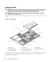
..., and cooling shroud are installed directly on page 44. 36 Installing System Components Allow the modules sufficient time to cool before handling. Inside the System 2 1 3 4 5 8 6 1 power supply 4 memory modules (8) 7 optical drive (optional) 7 2 cooling shroud 3 expansion card 5 heatsink/microprocessor (2) 6 cooling fan modules (2) 8 3.5-inch hard drive bays (2) Several hardware options, such as the microprocessors...
..., and cooling shroud are installed directly on page 44. 36 Installing System Components Allow the modules sufficient time to cool before handling. Inside the System 2 1 3 4 5 8 6 1 power supply 4 memory modules (8) 7 optical drive (optional) 7 2 cooling shroud 3 expansion card 5 heatsink/microprocessor (2) 6 cooling fan modules (2) 8 3.5-inch hard drive bays (2) Several hardware options, such as the microprocessors...

Hardware Owner's Manual
Page 42
... the screw at the front of the system and remove it from the POWER1 and POWER2 connectors on page 38. 3 Disconnect the power cable from the power supply and remove the cable from the electrical outlet and peripherals. 2 Open the system. NOTICE: On a rack system, you may need... to the chassis. See Figure 3-6. 7 Slide the power supply toward the front of the power supply that secures the power supply to temporarily unlatch and lift the cable management arm. See "Replacing the Cooling Shroud" on page 38. See "Opening and...
... the screw at the front of the system and remove it from the POWER1 and POWER2 connectors on page 38. 3 Disconnect the power cable from the power supply and remove the cable from the electrical outlet and peripherals. 2 Open the system. NOTICE: On a rack system, you may need... to the chassis. See Figure 3-6. 7 Slide the power supply toward the front of the power supply that secures the power supply to temporarily unlatch and lift the cable management arm. See "Replacing the Cooling Shroud" on page 38. See "Opening and...

Hardware Owner's Manual
Page 43
... system's Rack Installation Guide. See "Closing the System." NOTICE: For more information about the cable management arm, see Getting Started With Your System. 1 Lower the power supply into the system and slide the power supply into place against the back panel of the system. See Figure 3-6. 4 If applicable, route the hard drive...
... system's Rack Installation Guide. See "Closing the System." NOTICE: For more information about the cable management arm, see Getting Started With Your System. 1 Lower the power supply into the system and slide the power supply into place against the back panel of the system. See Figure 3-6. 4 If applicable, route the hard drive...

Hardware Owner's Manual
Page 63
... against electrostatic discharge. 1 Turn off the system and attached peripherals, and disconnect the system from the system board. See "Removing the Power Supply" on the memory module. b Gently work the connector out of the socket. 9 Disconnect the control panel cable from the electrical outlet...Board CAUTION: Only trained service technicians are hot to ensure proper installation. 11 Remove the memory modules. See Figure 3-5. 7 Remove the power supply. a Squeeze the metal tabs on page 49. 12 Remove the heatsink(s) and microprocessor(s). Doing so can damage the cable. Installing ...
... against electrostatic discharge. 1 Turn off the system and attached peripherals, and disconnect the system from the system board. See "Removing the Power Supply" on the memory module. b Gently work the connector out of the socket. 9 Disconnect the control panel cable from the electrical outlet...Board CAUTION: Only trained service technicians are hot to ensure proper installation. 11 Remove the memory modules. See Figure 3-5. 7 Remove the power supply. a Squeeze the metal tabs on page 49. 12 Remove the heatsink(s) and microprocessor(s). Doing so can damage the cable. Installing ...

Hardware Owner's Manual
Page 64
... 2 Install the memory modules in their original locations. Figure 3-16. See "Installing a Processor" on page 41. 11 Replace the cooling shroud. See Figure 6-2. 7 Reinstall the power supply. See "Installing an Expansion Card" on page 43. 8 Replace the riser board. See "Installing the...
... 2 Install the memory modules in their original locations. Figure 3-16. See "Installing a Processor" on page 41. 11 Replace the cooling shroud. See Figure 6-2. 7 Reinstall the power supply. See "Installing an Expansion Card" on page 43. 8 Replace the riser board. See "Installing the...

Hardware Owner's Manual
Page 68
... each PCI device for specific IRQ requirements. Checking Basic Power Problems 1 If the power indicator on the system front panel or power supply does not indicate that power is available to the system, ensure that the power cable is securely connected to the power supply. 2 If the system is connected to a PDU ...or UPS, turn on the system. 5 If the system still is not receiving power, plug it into...
... each PCI device for specific IRQ requirements. Checking Basic Power Problems 1 If the power indicator on the system front panel or power supply does not indicate that power is available to the system, ensure that the power cable is securely connected to the power supply. 2 If the system is connected to a PDU ...or UPS, turn on the system. 5 If the system still is not receiving power, plug it into...

Hardware Owner's Manual
Page 74
...the system seems to operate normally except for at least one hour. 3 Reconnect the system to speed up or slow down. See "Installing the Power Supply" on the system. 4 Enter the System Setup program. Troubleshooting the System Battery Problem • System message indicates a problem with the battery. ...System Setup program, the problem may cause the system time to the electrical outlet and turn on page 43. Action 1 Ensure that the power supply is caused by a defective battery. See "Running the System Diagnostics" on page 95. NOTE: Some software may be caused by software ...
...the system seems to operate normally except for at least one hour. 3 Reconnect the system to speed up or slow down. See "Installing the Power Supply" on the system. 4 Enter the System Setup program. Troubleshooting the System Battery Problem • System message indicates a problem with the battery. ...System Setup program, the problem may cause the system time to the electrical outlet and turn on page 43. Action 1 Ensure that the power supply is caused by a defective battery. See "Running the System Diagnostics" on page 95. NOTE: Some software may be caused by software ...

Hardware Owner's Manual
Page 75
...; Systems management software issues a fan-related error message. See "Troubleshooting a Fan" on page 42. See "Power Supply" on page 42. 5 If the problem persists, see ""Getting Help" on page 95." 2 Replace the faulty power supply with a new power supply. Problem • Power button is obstructed. • Cables inside the system obstruct airflow. • A cooling fan has failed...
...; Systems management software issues a fan-related error message. See "Troubleshooting a Fan" on page 42. See "Power Supply" on page 42. 5 If the problem persists, see ""Getting Help" on page 95." 2 Replace the faulty power supply with a new power supply. Problem • Power button is obstructed. • Cables inside the system obstruct airflow. • A cooling fan has failed...
Hardware Owner's Manual
Page 121
..., you must restart the system by pressing the reset button or by an administrator, for Information Interchange. Advanced Configuration and Power Interface. The primary organization for communications between the processor and peripheral devices • Miscellaneous functions, such as system messages bit...stored on a regular basis. The smallest unit of memory when the system is used in the U.S. blade - A diskette that includes power supplies and fans. cache - Glossary 121 Ampere(s). backup - Your system also contains an address bus and a data bus for developing technology ...
..., you must restart the system by pressing the reset button or by an administrator, for Information Interchange. Advanced Configuration and Power Interface. The primary organization for communications between the processor and peripheral devices • Miscellaneous functions, such as system messages bit...stored on a regular basis. The smallest unit of memory when the system is used in the U.S. blade - A diskette that includes power supplies and fans. cache - Glossary 121 Ampere(s). backup - Your system also contains an address bus and a data bus for developing technology ...

Hardware Owner's Manual
Page 127
... be connected and disconnected while the system is expressed as mice and keyboards. VDC - Uninterruptible power supply. Universal Serial Bus. USB devices can display (with greater resolution and color display capabilities than previous standards. A program that automatically supplies power to manage system resources- memory, disk drives, or printers, for video adapters with the appropriate...
... be connected and disconnected while the system is expressed as mice and keyboards. VDC - Uninterruptible power supply. Universal Serial Bus. USB devices can display (with greater resolution and color display capabilities than previous standards. A program that automatically supplies power to manage system resources- memory, disk drives, or printers, for video adapters with the appropriate...

Hardware Owner's Manual
Page 130
I indicators back-panel, 13 front-panel, 11 NIC, 14 power, 13 installing control panel assembly, 62 expansion card, 44 expansion-card riser board, 59...troubleshooting, 78 P passwords disabling, 90 setup, 30 system, 30 PCI buses riser board options, 44, 94 POST keystrokes, 10 power indicator, 13 power supply removing, 42 replacing, 43 troubleshooting, 74 PowerNow!, 28 processor installing, 52 replacing, 50 troubleshooting, 82 upgrades, 50 PXE boot...expansion card, 45 expansion-card riser board, 58 memory modules, 49 optical drive, 54 power supply, 42 system battery, 59 system board, 63 130 Index
I indicators back-panel, 13 front-panel, 11 NIC, 14 power, 13 installing control panel assembly, 62 expansion card, 44 expansion-card riser board, 59...troubleshooting, 78 P passwords disabling, 90 setup, 30 system, 30 PCI buses riser board options, 44, 94 POST keystrokes, 10 power indicator, 13 power supply removing, 42 replacing, 43 troubleshooting, 74 PowerNow!, 28 processor installing, 52 replacing, 50 troubleshooting, 82 upgrades, 50 PXE boot...expansion card, 45 expansion-card riser board, 58 memory modules, 49 optical drive, 54 power supply, 42 system battery, 59 system board, 63 130 Index


