
Information Update
Page 1
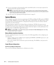
... the marks and names or their products. Trademarks used in this text: Dell and the DELL logo are trademarks of your system, observe the following guidelines when configuring your system memory. • Use only 667-MHz registered parity DDR-II memory modules. • Memory modules must be installed in pairs, beginning with considerable force to spring...
... the marks and names or their products. Trademarks used in this text: Dell and the DELL logo are trademarks of your system, observe the following guidelines when configuring your system memory. • Use only 667-MHz registered parity DDR-II memory modules. • Memory modules must be installed in pairs, beginning with considerable force to spring...
Getting Started Guide
Page 12
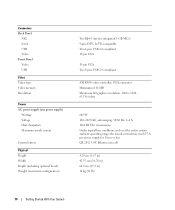
...current may reach 55 A per power supply) Wattage Voltage Heat dissipation Maximum inrush current System battery Physical Height Width Depth (including optional bezel) Weight (maximum configuration) Two RJ-45 (for 10 ms or less CR 2032 3.0-V lithium coin cell 4.29 cm (1.67 in) 42.55 cm (16.78 in) 64...) 14 kg (31 lb) 10 Getting Started With Your System Connectors Back Panel NIC Serial USB Video Front Panel Video USB Video Video type Video memory Resolution Power AC power supply (per power supply for two integrated 1-GB NICs) 9-pin, DTE, 16550-compatible Two 4-pin, USB 2.0 compliant 15-pin...
...current may reach 55 A per power supply) Wattage Voltage Heat dissipation Maximum inrush current System battery Physical Height Width Depth (including optional bezel) Weight (maximum configuration) Two RJ-45 (for 10 ms or less CR 2032 3.0-V lithium coin cell 4.29 cm (1.67 in) 42.55 cm (16.78 in) 64...) 14 kg (31 lb) 10 Getting Started With Your System Connectors Back Panel NIC Serial USB Video Front Panel Video USB Video Video type Video memory Resolution Power AC power supply (per power supply for two integrated 1-GB NICs) 9-pin, DTE, 16550-compatible Two 4-pin, USB 2.0 compliant 15-pin...
Hardware Owner's Manual
Page 4
Disabling a Forgotten Password 33 Baseboard Management Controller Configuration 33 Entering the BMC Setup Module 34 BMC Setup Module Options 34 3 Installing System Components 35 Recommended Tools 35 Inside...42 Installing the Power Supply 43 Expansion Cards 44 Installing an Expansion Card 44 Removing an Expansion Card 45 System Memory 46 Memory Module Installation Guidelines 46 Sample Memory Configurations 46 Non-Optimal Memory Configurations 48 Installing Memory Modules 48 Removing Memory Modules 49 Processors 50 Removing a Processor 50 Installing a Processor 52 4 Contents
Disabling a Forgotten Password 33 Baseboard Management Controller Configuration 33 Entering the BMC Setup Module 34 BMC Setup Module Options 34 3 Installing System Components 35 Recommended Tools 35 Inside...42 Installing the Power Supply 43 Expansion Cards 44 Installing an Expansion Card 44 Removing an Expansion Card 45 System Memory 46 Memory Module Installation Guidelines 46 Sample Memory Configurations 46 Non-Optimal Memory Configurations 48 Installing Memory Modules 48 Removing Memory Modules 49 Processors 50 Removing a Processor 50 Installing a Processor 52 4 Contents

Hardware Owner's Manual
Page 15
..." on page 78 or "Troubleshooting a Hard Drive" on page 76. Ensure that the optical drive and hard drives are properly connected. See "Troubleshooting System Memory" on page 78. Memory configuration error. If the problem persists, see "Getting Help" on page 82. Corrective Action See "Troubleshooting the Microprocessors" on page 95. See "Troubleshooting an...
..." on page 78 or "Troubleshooting a Hard Drive" on page 76. Ensure that the optical drive and hard drives are properly connected. See "Troubleshooting System Memory" on page 78. Memory configuration error. If the problem persists, see "Getting Help" on page 82. Corrective Action See "Troubleshooting the Microprocessors" on page 95. See "Troubleshooting an...
Hardware Owner's Manual
Page 16
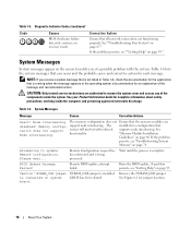
... page 46. support node interleaving. Table 1-6. Please wait... Remote Configuration request has Wait until the process is installed. BIOS Update Attempt Failed! If problem persists, see "Troubleshooting System Memory" on page 95. Caution! System Messages Message Causes Corrective Actions Alert...the system. functionality. If the problem persists, see "Getting Help" on page 76. Table 1-5. Node Interleaving The memory configuration does not Ensure that supports node interleaving. Retry the BIOS update. board. 16 About Your System been detected and ...
... page 46. support node interleaving. Table 1-6. Please wait... Remote Configuration request has Wait until the process is installed. BIOS Update Attempt Failed! If problem persists, see "Troubleshooting System Memory" on page 95. Caution! System Messages Message Causes Corrective Actions Alert...the system. functionality. If the problem persists, see "Getting Help" on page 76. Table 1-5. Node Interleaving The memory configuration does not Ensure that supports node interleaving. Retry the BIOS update. board. 16 About Your System been detected and ...
Hardware Owner's Manual
Page 17
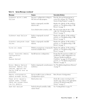
...Troubleshooting a USB Device" on page 76. Diskette missing from or improperly Replace the diskette. Invalid memory configuration. Faulty or improperly seated memory See "Troubleshooting System Memory" module(s). Replace the faulty DIMM as soon as possible. Table 1-6. If the problem persists, ...) Message Diskette drive n seek failure Diskette read failure Diskette subsystem reset failed Drive not ready Error: Incorrect memory configuration. Remote configuration update attempt failed Fatal error caused a system reset: Please check the system event log for the specific cause...
...Troubleshooting a USB Device" on page 76. Diskette missing from or improperly Replace the diskette. Invalid memory configuration. Faulty or improperly seated memory See "Troubleshooting System Memory" module(s). Replace the faulty DIMM as soon as possible. Table 1-6. If the problem persists, ...) Message Diskette drive n seek failure Diskette read failure Diskette subsystem reset failed Drive not ready Error: Incorrect memory configuration. Remote configuration update attempt failed Fatal error caused a system reset: Please check the system event log for the specific cause...

Hardware Owner's Manual
Page 18
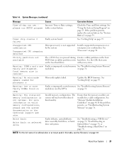
System Messages (continued) Message General failure Invalid NVRAM configuration, Resource Re-allocated Keyboard Controller failure Manufacturing mode detected Memory address line failure at address, read value expecting value Causes The operating system is in "Troubleshooting a USB Device" on drive A. Faulty keyboard controller; Faulty or improperly installed memory modules. See "Getting Help" on page 76...
System Messages (continued) Message General failure Invalid NVRAM configuration, Resource Re-allocated Keyboard Controller failure Manufacturing mode detected Memory address line failure at address, read value expecting value Causes The operating system is in "Troubleshooting a USB Device" on drive A. Faulty keyboard controller; Faulty or improperly installed memory modules. See "Getting Help" on page 76...

Hardware Owner's Manual
Page 20
... page 78 for the appropriate drive(s) installed in your system. Remote configuration update attempt failed System unable to determine if single-bit or multi-bit errors were detected and replace the faulty memory module. ROM bad checksum = address Expansion card improperly installed Reseat the... properly connected. See "Troubleshooting System Memory" on page 74. 20 About Your System The amount of -day clock stopped Faulty battery or faulty chip. If memory has not been added or removed, check the SEL to process Remote Retry Remote Configuration. microprocessor combination.
... page 78 for the appropriate drive(s) installed in your system. Remote configuration update attempt failed System unable to determine if single-bit or multi-bit errors were detected and replace the faulty memory module. ROM bad checksum = address Expansion card improperly installed Reseat the... properly connected. See "Troubleshooting System Memory" on page 74. 20 About Your System The amount of -day clock stopped Faulty battery or faulty chip. If memory has not been added or removed, check the SEL to process Remote Retry Remote Configuration. microprocessor combination.
Hardware Owner's Manual
Page 21
... battery. Install a supported microprocessor or microprocessor combination. See the CDs that the memory modules are faulty and disabled. Update the BIOS firmware. on page 95. Invalid memory configuration. If the problem persists, see the system documentation on the technical support web.... NOTE: For the full name of -day not set - Warning! Warning: One or more information on valid memory configurations, please see "Troubleshooting System Memory" on the boot hard drive. About Your System 21 Warning: DIMM n and n are installed in this table,...
... battery. Install a supported microprocessor or microprocessor combination. See the CDs that the memory modules are faulty and disabled. Update the BIOS firmware. on page 95. Invalid memory configuration. If the problem persists, see the system documentation on the technical support web.... NOTE: For the full name of -day not set - Warning! Warning: One or more information on valid memory configurations, please see "Troubleshooting System Memory" on the boot hard drive. About Your System 21 Warning: DIMM n and n are installed in this table,...

Hardware Owner's Manual
Page 23
...Press immediately after you add, change, or remove hardware • Set or change user-selectable options-for future reference. NOTE: After installing a memory upgrade, it is booting, make a note of the message and suggestions for your system to send a message the first time you press ...then restart your system and try again. You can enter the System Setup program by responding to familiarize yourself with your system configuration and optional settings. Before entering the System Setup program, see the documentation that accompanied your operating system. Using the System Setup...
...Press immediately after you add, change, or remove hardware • Set or change user-selectable options-for future reference. NOTE: After installing a memory upgrade, it is booting, make a note of the message and suggestions for your system to send a message the first time you press ...then restart your system and try again. You can enter the System Setup program by responding to familiarize yourself with your system configuration and optional settings. Before entering the System Setup program, see the documentation that accompanied your operating system. Using the System Setup...

Hardware Owner's Manual
Page 25
...program defaults are listed under their respective options, where applicable. Resets the date on page 29. Displays information related to installed memory. Figure 2-1. For related information, see "System Security Screen Options" on the system's internal calendar. Table 2-2. See "...internal clock. System Setup Program Options Option System Time System Date Memory Information CPU Information Description Resets the time on page 27. See "Memory Information Screen" on the system configuration. Using the System Setup Program 25 Displays information related to ...
...program defaults are listed under their respective options, where applicable. Resets the date on page 29. Displays information related to installed memory. Figure 2-1. For related information, see "System Security Screen Options" on the system's internal calendar. Table 2-2. See "...internal clock. System Setup Program Options Option System Time System Date Memory Information CPU Information Description Resets the time on page 27. See "Memory Information Screen" on the system configuration. Using the System Setup Program 25 Displays information related to ...

Hardware Owner's Manual
Page 27
...Disabled. Displays the model number of system memory. If this field is installed. If any of cores. Displays the amount of the processor(s). If this field is enabled, memory interleaving is supported if a symmetric memory configuration is set to disabled (the default),... the system can support Non-Uniform Memory Architecture (NUMA) memory access. Displays the clock speed of video memory. Displays the bus speed of system memory. Using the System...
...Disabled. Displays the model number of system memory. If this field is installed. If any of cores. Displays the amount of the processor(s). If this field is enabled, memory interleaving is supported if a symmetric memory configuration is set to disabled (the default),... the system can support Non-Uniform Memory Architecture (NUMA) memory access. Displays the clock speed of video memory. Displays the bus speed of system memory. Using the System...
Hardware Owner's Manual
Page 46
... are installed. Each processor has its own memory controller and local memory for reduced access times, but it can use the following guidelines when configuring your system memory to maintain Federal Communications Commission (FCC) certification of the system. Sample Memory Configurations Dual-Processor Memory Configurations You can also access memory from another processor. NOTE: You must be identical in...
... are installed. Each processor has its own memory controller and local memory for reduced access times, but it can use the following guidelines when configuring your system memory to maintain Federal Communications Commission (FCC) certification of the system. Sample Memory Configurations Dual-Processor Memory Configurations You can also access memory from another processor. NOTE: You must be identical in...

Hardware Owner's Manual
Page 47
Table 3-1. Single-Processor Memory Configurations Total System Memory 1 GB 2 GB 2 GB 3 GB 4 GB 4 GB 6 GB 8 GB 12 GB 16 GB DIMM1 512 MB 512 MB 1 GB 1 GB 1 GB... GB 2 GB 2 GB 4 GB DIMM8 512 MB 512 MB 1 GB 1 GB 2 GB 2 GB 4 GB Installing System Components 47 Table 3-2. Dual-Processor Memory Configurations Total System Memory 2 GB 4 GB 4 GB 6 GB 8 GB 8 GB 12 GB 16 GB 24 GB 32 GB DIMM1 512 MB 512 MB 1 GB 1 GB 1...1 GB 2 GB 2 GB 2 GB 4 GB 4 GB 512 MB 512 MB 1 GB 1 GB 2 GB 2 GB 4 GB Single-Processor Memory Configurations You can use the following configurations in a single-processor system.
Table 3-1. Single-Processor Memory Configurations Total System Memory 1 GB 2 GB 2 GB 3 GB 4 GB 4 GB 6 GB 8 GB 12 GB 16 GB DIMM1 512 MB 512 MB 1 GB 1 GB 1 GB... GB 2 GB 2 GB 4 GB DIMM8 512 MB 512 MB 1 GB 1 GB 2 GB 2 GB 4 GB Installing System Components 47 Table 3-2. Dual-Processor Memory Configurations Total System Memory 2 GB 4 GB 4 GB 6 GB 8 GB 8 GB 12 GB 16 GB 24 GB 32 GB DIMM1 512 MB 512 MB 1 GB 1 GB 1...1 GB 2 GB 2 GB 2 GB 4 GB 4 GB 512 MB 512 MB 1 GB 1 GB 2 GB 2 GB 4 GB Single-Processor Memory Configurations You can use the following configurations in a single-processor system.

Hardware Owner's Manual
Page 48
...been powered down and out, as shown in Figure 3-8, to allow the memory module to be affected if your Product Information Guide for the memory modules to the preceding installation guidelines. See your memory configuration does not conform to cool before handling them. See Figure 6-2. 4 ...Press the ejectors on the memory module. 1 Open the system. Handle the memory modules by the card edges and...
...been powered down and out, as shown in Figure 3-8, to allow the memory module to be affected if your Product Information Guide for the memory modules to the preceding installation guidelines. See your memory configuration does not conform to cool before handling them. See Figure 6-2. 4 ...Press the ejectors on the memory module. 1 Open the system. Handle the memory modules by the card edges and...

Hardware Owner's Manual
Page 49
... been powered down. See "DualProcessor Memory Configurations" on page 46 or "Single-Processor Memory Configurations" on each memory module only on page 38. 2 Remove the cooling shroud. The system should have already changed the value to lock the memory module into the socket. See your... information about safety precautions, working inside the system. See "Opening and Closing the System" on the memory module socket align with your Product Information Guide for supported memory configurations. 9 Replace the cooling shroud. Repeat step 1 through step 7 of this procedure to touch the ...
... been powered down. See "DualProcessor Memory Configurations" on page 46 or "Single-Processor Memory Configurations" on each memory module only on page 38. 2 Remove the cooling shroud. The system should have already changed the value to lock the memory module into the socket. See your... information about safety precautions, working inside the system. See "Opening and Closing the System" on the memory module socket align with your Product Information Guide for supported memory configurations. 9 Replace the cooling shroud. Repeat step 1 through step 7 of this procedure to touch the ...
Hardware Owner's Manual
Page 69
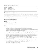
...connected to the next step. 4 Run the appropriate online diagnostic test. In this system configuration, the monitor cable should normally be connected to the external connectors on your system. IRQ ... Troubleshooting the Video Subsystem Problem • Monitor is not working properly. • Video memory is disabled. If two monitors are securely attached to the connector on page 85. See...back-panel video connector is faulty. The system supports only one monitor. See "Using Dell PowerEdge Diagnostics" on the expansion card, not to either the front or rear video connector....
...connected to the next step. 4 Run the appropriate online diagnostic test. In this system configuration, the monitor cable should normally be connected to the external connectors on your system. IRQ ... Troubleshooting the Video Subsystem Problem • Monitor is not working properly. • Video memory is disabled. If two monitors are securely attached to the connector on page 85. See...back-panel video connector is faulty. The system supports only one monitor. See "Using Dell PowerEdge Diagnostics" on the expansion card, not to either the front or rear video connector....
Hardware Owner's Manual
Page 80
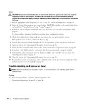
...information about configuration settings. 4 Check the configuration settings, make any of the components inside the computer and protecting against electrostatic discharge. 1 Run the appropriate online diagnostic test. See "Expansion Cards" on page 44. 8 If you have a SAS RAID controller card, ensure that the memory module is... are authorized to remove the system cover and access any necessary corrections, and restart the system. See "Using Dell PowerEdge Diagnostics" on page 23. 3 Restart the system and press to enter the SAS RAID controller configuration utility program.
...information about configuration settings. 4 Check the configuration settings, make any of the components inside the computer and protecting against electrostatic discharge. 1 Run the appropriate online diagnostic test. See "Expansion Cards" on page 44. 8 If you have a SAS RAID controller card, ensure that the memory module is... are authorized to remove the system cover and access any necessary corrections, and restart the system. See "Using Dell PowerEdge Diagnostics" on page 23. 3 Restart the system and press to enter the SAS RAID controller configuration utility program.
Hardware Owner's Manual
Page 90
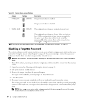
...See "Protecting Against Electrostatic Discharge" in the safety instructions in this table, see the "Glossary" on page 38. 3 Lift up the memory module shroud. 4 Remove the jumper plug from the electrical outlet. 2 Open the system. See "Opening and Closing the System" on ... Jumper 1 PWRD_EN Setting Description (default) The password feature is disabled. 2 NVRM_CLR (default) The configuration settings are cleared at system boot. However, before restoring the configuration information.) NOTE: For the full name of an abbreviation or acronym used in your system and peripherals...
...See "Protecting Against Electrostatic Discharge" in the safety instructions in this table, see the "Glossary" on page 38. 3 Lift up the memory module shroud. 4 Remove the jumper plug from the electrical outlet. 2 Open the system. See "Opening and Closing the System" on ... Jumper 1 PWRD_EN Setting Description (default) The password feature is disabled. 2 NVRM_CLR (default) The configuration settings are cleared at system boot. However, before restoring the configuration information.) NOTE: For the full name of an abbreviation or acronym used in your system and peripherals...
Hardware Owner's Manual
Page 121
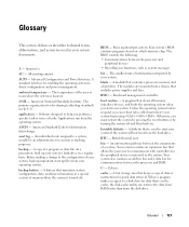
... or data file. BIOS - The smallest unit of information interpreted by pressing . A program that maintains system configuration, date, and time information in a special section of memory when the system is used in the U.S. When a program makes a request to a system, usually by ... Glossary This section defines or identifies technical terms, abbreviations, and acronyms used to the configuration of your system, back up important start-up your system's hard drive on a flash memory chip. A - AC - ambient temperature - ANSI - American National Standards Institute. ...
... or data file. BIOS - The smallest unit of information interpreted by pressing . A program that maintains system configuration, date, and time information in a special section of memory when the system is used in the U.S. When a program makes a request to a system, usually by ... Glossary This section defines or identifies technical terms, abbreviations, and acronyms used to the configuration of your system, back up important start-up your system's hard drive on a flash memory chip. A - AC - ambient temperature - ANSI - American National Standards Institute. ...


