
Information Update
Page 1
... entities claiming the marks and names or their products. Printed in this document is strictly forbidden. Dell Inc. Updated Memory Module Installation Guidelines To ensure optimal performance of Dell Inc. disclaims any manner whatsoever without notice. © 2006 Dell Inc. Update to Processor Installation During processor installation or replacement, be the same size. Information...
... entities claiming the marks and names or their products. Printed in this document is strictly forbidden. Dell Inc. Updated Memory Module Installation Guidelines To ensure optimal performance of Dell Inc. disclaims any manner whatsoever without notice. © 2006 Dell Inc. Update to Processor Installation During processor installation or replacement, be the same size. Information...

Getting Started Guide
Page 5
...hard drives. (An optional SAS controller card is 1600x1200 with 65,536 colors. • Systems management circuitry that monitors operation of graphics memory and supports various 2D graphics video modes. A riser card supporting one 3.3-V, 64-bit, 133-MHz PCI-X half-length expansion slot. ...8226; Front-panel connectors including a video connector and two USB connectors. Memory is upgradable to a maximum of 32 GB by installing combinations of 512-MB, 1-GB, 2-GB, or 4-GB memory modules in the eight memory module sockets on the system board. • Support for SAS hard-drive...
...hard drives. (An optional SAS controller card is 1600x1200 with 65,536 colors. • Systems management circuitry that monitors operation of graphics memory and supports various 2D graphics video modes. A riser card supporting one 3.3-V, 64-bit, 133-MHz PCI-X half-length expansion slot. ...8226; Front-panel connectors including a video connector and two USB connectors. Memory is upgradable to a maximum of 32 GB by installing combinations of 512-MB, 1-GB, 2-GB, or 4-GB memory modules in the eight memory module sockets on the system board. • Support for SAS hard-drive...

Getting Started Guide
Page 11
... operating system, see the Quick Installation Guide. Technical Specifications Processor Processor type Expansion Bus Bus type Expansion slots via riser card: Memory Architecture Memory module sockets Memory module capacities Minimum RAM Maximum RAM Drives SATA hard drives SAS hard drives Optical drive One or two dual-core AMD Opteron 2000... Series processors PCI-X, PCIe One x8 lane-width PCIe slot or One 3.3-V, 64-bit, 133-MHz PCI-X slot 667-MHz DDR-II memory modules Eight 240-pin 512 MB, 1 GB, 2 GB, 4 GB 1 GB (one processor) or 2 GB (two processors) 32 GB One or two ...
... operating system, see the Quick Installation Guide. Technical Specifications Processor Processor type Expansion Bus Bus type Expansion slots via riser card: Memory Architecture Memory module sockets Memory module capacities Minimum RAM Maximum RAM Drives SATA hard drives SAS hard drives Optical drive One or two dual-core AMD Opteron 2000... Series processors PCI-X, PCIe One x8 lane-width PCIe slot or One 3.3-V, 64-bit, 133-MHz PCI-X slot 667-MHz DDR-II memory modules Eight 240-pin 512 MB, 1 GB, 2 GB, 4 GB 1 GB (one processor) or 2 GB (two processors) 32 GB One or two ...
Getting Started Guide
Page 12
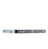
...) 14 kg (31 lb) 10 Getting Started With Your System Connectors Back Panel NIC Serial USB Video Front Panel Video USB Video Video type Video memory Resolution Power AC power supply (per power supply for two integrated 1-GB NICs) 9-pin, DTE, 16550-compatible Two 4-pin, USB 2.0 compliant 15-pin VGA 15...
...) 14 kg (31 lb) 10 Getting Started With Your System Connectors Back Panel NIC Serial USB Video Front Panel Video USB Video Video type Video memory Resolution Power AC power supply (per power supply for two integrated 1-GB NICs) 9-pin, DTE, 16550-compatible Two 4-pin, USB 2.0 compliant 15-pin VGA 15...

Hardware Owner's Manual
Page 3
... 23 Entering the System Setup Program 23 Responding to Error Messages 23 Using the System Setup Program 24 System Setup Options 24 Main Screen 24 Memory Information Screen 27 CPU Information Screen 27 Integrated Devices Screen 28 System Security Screen 29 Exit Screen 30 System and Setup Password Features 30 Using...
... 23 Entering the System Setup Program 23 Responding to Error Messages 23 Using the System Setup Program 24 System Setup Options 24 Main Screen 24 Memory Information Screen 27 CPU Information Screen 27 Integrated Devices Screen 28 System Security Screen 29 Exit Screen 30 System and Setup Password Features 30 Using...
Hardware Owner's Manual
Page 4
... the Power Supply 42 Installing the Power Supply 43 Expansion Cards 44 Installing an Expansion Card 44 Removing an Expansion Card 45 System Memory 46 Memory Module Installation Guidelines 46 Sample Memory Configurations 46 Non-Optimal Memory Configurations 48 Installing Memory Modules 48 Removing Memory Modules 49 Processors 50 Removing a Processor 50 Installing a Processor 52 4 Contents
... the Power Supply 42 Installing the Power Supply 43 Expansion Cards 44 Installing an Expansion Card 44 Removing an Expansion Card 45 System Memory 46 Memory Module Installation Guidelines 46 Sample Memory Configurations 46 Non-Optimal Memory Configurations 48 Installing Memory Modules 48 Removing Memory Modules 49 Processors 50 Removing a Processor 50 Installing a Processor 52 4 Contents

Hardware Owner's Manual
Page 6
... System Cooling Problems 75 Troubleshooting a Fan 75 Troubleshooting System Memory 76 Troubleshooting an Optical Drive 78 Troubleshooting a Hard Drive 78 Troubleshooting a SAS RAID Controller Card 79 Troubleshooting an Expansion Card 80 Troubleshooting the Microprocessors 82 5 Running the System Diagnostics 85 Using Dell PowerEdge Diagnostics 85 System Diagnostics Features 85 When to Use the...
... System Cooling Problems 75 Troubleshooting a Fan 75 Troubleshooting System Memory 76 Troubleshooting an Optical Drive 78 Troubleshooting a Hard Drive 78 Troubleshooting a SAS RAID Controller Card 79 Troubleshooting an Expansion Card 80 Troubleshooting the Microprocessors 82 5 Running the System Diagnostics 85 Using Dell PowerEdge Diagnostics 85 System Diagnostics Features 85 When to Use the...

Hardware Owner's Manual
Page 15
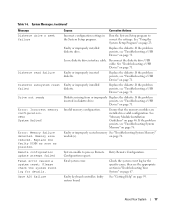
...Possible system resource configuration error. Other failure. About Your System 15 Possible expansion card failure. System board failure. See "Troubleshooting System Memory" on page 78. If the problem persists, see "Getting Help" on page 95. If the problem persists, see "Getting ...Help" on page 71. Hard drive failure. Memory configuration error. See "Troubleshooting IRQ Assignment Conflicts" on page 82. Corrective Action See "Troubleshooting the Microprocessors" on page 68. Ensure ...
...Possible system resource configuration error. Other failure. About Your System 15 Possible expansion card failure. System board failure. See "Troubleshooting System Memory" on page 78. If the problem persists, see "Getting Help" on page 95. If the problem persists, see "Getting ...Help" on page 71. Hard drive failure. Memory configuration error. See "Troubleshooting IRQ Assignment Conflicts" on page 82. Corrective Action See "Troubleshooting the Microprocessors" on page 68. Ensure ...
Hardware Owner's Manual
Page 16
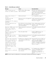
...cause and corrective action for each message. Table 1-6 lists the system messages that all network connections are functioning properly. Table 1-6. Memory configu- The ration does not support system will run but with the system. functionality. If problem persists, see "Getting Help...message and recommended action. Remove the NVRAM_CLR jumper. board. 16 About Your System If the problem persists, see "Troubleshooting System Memory" on page 67." NOTE: If you of the components inside the computer, and protecting against electrostatic discharge. support node ...
...cause and corrective action for each message. Table 1-6 lists the system messages that all network connections are functioning properly. Table 1-6. Memory configu- The ration does not support system will run but with the system. functionality. If problem persists, see "Getting Help...message and recommended action. Remove the NVRAM_CLR jumper. board. 16 About Your System If the problem persists, see "Troubleshooting System Memory" on page 67." NOTE: If you of the components inside the computer, and protecting against electrostatic discharge. support node ...
Hardware Owner's Manual
Page 17
...Reconnect the diskette drive USB cable. Ensure that the memory modules are installed in diskette drive. See "Memory Module Installation Guidelines" on page 71. Faulty or improperly seated memory See "Troubleshooting System Memory" module(s). Replace the diskette. Faulty or improperly .... Faulty or improperly inserted diskette. Replace the diskette. If the problem persists, see "Troubleshooting System Memory" on page 67. Invalid memory configuration. Check the system event log for details. Gate A20 failure Causes Corrective Actions Incorrect configuration settings...
...Reconnect the diskette drive USB cable. Ensure that the memory modules are installed in diskette drive. See "Memory Module Installation Guidelines" on page 71. Faulty or improperly seated memory See "Troubleshooting System Memory" module(s). Replace the diskette. Faulty or improperly .... Faulty or improperly inserted diskette. Replace the diskette. If the problem persists, see "Troubleshooting System Memory" on page 67. Invalid memory configuration. Check the system event log for details. Gate A20 failure Causes Corrective Actions Incorrect configuration settings...

Hardware Owner's Manual
Page 18
...1-6. System Messages (continued) Message General failure Invalid NVRAM configuration, Resource Re-allocated Keyboard Controller failure Manufacturing mode detected Memory address line failure at address, read value expecting value Causes The operating system is required. Note the information and... or hard- See "Using the System Setup Program" on page 76. Faulty or improperly installed memory modules. Faulty keyboard controller; See "Troubleshooting System Memory" on page 23 for information about setting the order of manufacturing mode. System detected and corrected...
...1-6. System Messages (continued) Message General failure Invalid NVRAM configuration, Resource Re-allocated Keyboard Controller failure Manufacturing mode detected Memory address line failure at address, read value expecting value Causes The operating system is required. Note the information and... or hard- See "Using the System Setup Program" on page 76. Faulty or improperly installed memory modules. Faulty keyboard controller; See "Troubleshooting System Memory" on page 23 for information about setting the order of manufacturing mode. System detected and corrected...

Hardware Owner's Manual
Page 20
...in your system. If the problem persists, see "Troubleshooting an Expansion Card" on page 74. 20 About Your System page 78. See "Troubleshooting System Memory" on the disk, or the requested sector is defective. microprocessor combination. Sector not found The operating system cannot read from the diskette or hard drive..., the system could not find a particular sector on page 76. If memory has not been added or removed, check the SEL to determine if single-bit or multi-bit errors were detected and replace the faulty...
...in your system. If the problem persists, see "Troubleshooting an Expansion Card" on page 74. 20 About Your System page 78. See "Troubleshooting System Memory" on the disk, or the requested sector is defective. microprocessor combination. Sector not found The operating system cannot read from the diskette or hard drive..., the system could not find a particular sector on page 76. If memory has not been added or removed, check the SEL to determine if single-bit or multi-bit errors were detected and replace the faulty...
Hardware Owner's Manual
Page 21
... Help" on page 50. See "Processors" on page 95. Warning: DIMM n and n are installed in this table, see "Troubleshooting System Memory" on the technical support web site. Warning! on page 78. See "Troubleshooting a USB Device" on page 71, "Troubleshooting an Optical Drive..." on page 78, or "Troubleshooting a Hard Drive" on page 76. About Your System 21 See "Memory Module Installation Guidelines" on page 23. Unsupported CPU combination Unsupported CPU stepping detected Microprocessor(s) is not supported by CPUn. See the CDs ...
... Help" on page 50. See "Processors" on page 95. Warning: DIMM n and n are installed in this table, see "Troubleshooting System Memory" on the technical support web site. Warning! on page 78. See "Troubleshooting a USB Device" on page 71, "Troubleshooting an Optical Drive..." on page 78, or "Troubleshooting a Hard Drive" on page 76. About Your System 21 See "Memory Module Installation Guidelines" on page 23. Unsupported CPU combination Unsupported CPU stepping detected Microprocessor(s) is not supported by CPUn. See the CDs ...

Hardware Owner's Manual
Page 23
... System Setup program to: • Change the system configuration stored in NVRAM after you see the documentation that accompanied your operating system. NOTE: After installing a memory upgrade, it is booting, make a note of the message and suggestions for future reference. Before entering the System Setup program, see "System Messages" on page...
... System Setup program to: • Change the system configuration stored in NVRAM after you see the documentation that accompanied your operating system. NOTE: After installing a memory upgrade, it is booting, make a note of the message and suggestions for future reference. Before entering the System Setup program, see "System Messages" on page...

Hardware Owner's Manual
Page 24
... System Setup program screen appears (see Figure 2-1). 24 Using the System Setup Program From the main menu, selects an option that has a submenu, such as Memory Information. From a submenu, returns the program to the previous field. From the main menu, exits the System Setup program and restarts the system if any...
... System Setup program screen appears (see Figure 2-1). 24 Using the System Setup Program From the main menu, selects an option that has a submenu, such as Memory Information. From a submenu, returns the program to the previous field. From the main menu, exits the System Setup program and restarts the system if any...

Hardware Owner's Manual
Page 25
...Options" on the system's internal clock. Table 2-2. System Setup Program Options Option System Time System Date Memory Information CPU Information Description Resets the time on page 29. Displays information related to installed memory. Figure 2-1. Main System Setup Program Screen Table 2-2 lists the options and descriptions for the System Setup.... Using the System Setup Program 25 NOTE: The System Setup program defaults are listed under their respective options, where applicable. See "Memory Information Screen" on page 27. See "CPU Information Screen" on page 27.
...Options" on the system's internal clock. Table 2-2. System Setup Program Options Option System Time System Date Memory Information CPU Information Description Resets the time on page 29. Displays information related to installed memory. Figure 2-1. Main System Setup Program Screen Table 2-2 lists the options and descriptions for the System Setup.... Using the System Setup Program 25 NOTE: The System Setup program defaults are listed under their respective options, where applicable. See "Memory Information Screen" on page 27. See "CPU Information Screen" on page 27.

Hardware Owner's Manual
Page 27
... information fields that appear on page 46. This option determines whether system memory tests are Enabled and Disabled. See "Memory Module Installation Guidelines" on the Memory Information screen. Displays the system memory speed. Options are run at system boot. when disabled, the CPU ... State tables will be reported to disabled (the default), the system can support Non-Uniform Memory Architecture (NUMA) memory access. Displays the model number of system memory. Displays the type of the processor. Using the System Setup Program 27 Displays the amount of...
... information fields that appear on page 46. This option determines whether system memory tests are Enabled and Disabled. See "Memory Module Installation Guidelines" on the Memory Information screen. Displays the system memory speed. Options are run at system boot. when disabled, the CPU ... State tables will be reported to disabled (the default), the system can support Non-Uniform Memory Architecture (NUMA) memory access. Displays the model number of system memory. Displays the type of the processor. Using the System Setup Program 27 Displays the amount of...

Hardware Owner's Manual
Page 35
... the following system components: • Front bezel • System cover • Cooling shroud • Cooling fan modules • Power supply • Expansion cards • System memory • Processors • Optical drive • Hard drives • Boot drive • SAS controller card • System battery • Risers • Control panel assembly •...
... the following system components: • Front bezel • System cover • Cooling shroud • Cooling fan modules • Power supply • Expansion cards • System memory • Processors • Optical drive • Hard drives • Boot drive • SAS controller card • System battery • Risers • Control panel assembly •...
Hardware Owner's Manual
Page 36
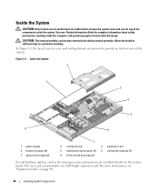
...are authorized to remove the system cover and access any of the system. Inside the System 2 1 3 4 5 8 6 1 power supply 4 memory modules (8) 7 optical drive (optional) 7 2 cooling shroud 3 expansion card 5 heatsink/microprocessor (2) 6 cooling fan modules (2) 8 3.5-inch hard drive ...bays (2) Several hardware options, such as the microprocessors and memory, are removed to cool before handling. The riser card accommodates one half-length expansion card. In Figure 3-1, the bezel, system cover...
...are authorized to remove the system cover and access any of the system. Inside the System 2 1 3 4 5 8 6 1 power supply 4 memory modules (8) 7 optical drive (optional) 7 2 cooling shroud 3 expansion card 5 heatsink/microprocessor (2) 6 cooling fan modules (2) 8 3.5-inch hard drive ...bays (2) Several hardware options, such as the microprocessors and memory, are removed to cool before handling. The riser card accommodates one half-length expansion card. In Figure 3-1, the bezel, system cover...

Hardware Owner's Manual
Page 38
CAUTION: Whenever you need to lift the system, get others to cool before handling. CAUTION: The memory modules can become extremely hot during normal operation. Allow the modules sufficient time to assist you. Figure 3-3. See your Product Information Guide for complete information ...
CAUTION: Whenever you need to lift the system, get others to cool before handling. CAUTION: The memory modules can become extremely hot during normal operation. Allow the modules sufficient time to assist you. Figure 3-3. See your Product Information Guide for complete information ...


