
Installation and Troubleshooting Guide (.htm)
Page 8
...Use caution when pressing the component rail release latches and sliding a component into the rack. • Do not overload the AC power supply branch circuit that provides power to the rack. One rack kit is intended to be installed in damage to components in the rack. • Do not ...industry-standard rack cabinets that meets the specifications of a rack; the slide rails can be installed without tools in a rack. 6 Dell™ Rack Installation Guide The RapidRails rack kit can pinch your system. CAUTION: Do not install rack kit components designed for another system.
...Use caution when pressing the component rail release latches and sliding a component into the rack. • Do not overload the AC power supply branch circuit that provides power to the rack. One rack kit is intended to be installed in damage to components in the rack. • Do not ...industry-standard rack cabinets that meets the specifications of a rack; the slide rails can be installed without tools in a rack. 6 Dell™ Rack Installation Guide The RapidRails rack kit can pinch your system. CAUTION: Do not install rack kit components designed for another system.

Installation and Troubleshooting Guide (.htm)
Page 24
... 3 release latch 5 system status indicator slot 5 2 strain-relief loops (1 per power supply, if available) 4 system status indicator 4 Attach the I/O cable connectors and power cable connectors to their respective connectors on the back of the power supplies to provide strain relief for the power cables. 22 Dell™ Rack Installation Guide For details on cable connections, see your...
... 3 release latch 5 system status indicator slot 5 2 strain-relief loops (1 per power supply, if available) 4 system status indicator 4 Attach the I/O cable connectors and power cable connectors to their respective connectors on the back of the power supplies to provide strain relief for the power cables. 22 Dell™ Rack Installation Guide For details on cable connections, see your...
Getting Started Guide
Page 5
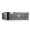
...MHz, Fully Buffered DIMMs (FBD), upgradable to a maximum of 128 GB by dividing microprocessor operations between independent microprocessors. See support.dell.com for an integrated RAID controller card with two or four Intel Xeon microprocessors. SMP greatly improves overall system performance by installing combinations... • One slimline IDE DVD-ROM/CD-RW drive or slimline SATA DVD-ROM/CD-RW drive (when available). • Two hot-pluggable power supplies in a 1 + 1 redundant configuration. • Four fan modules, each comprised of two dual-rotor fans, for a total of eight cooling...
...MHz, Fully Buffered DIMMs (FBD), upgradable to a maximum of 128 GB by dividing microprocessor operations between independent microprocessors. See support.dell.com for an integrated RAID controller card with two or four Intel Xeon microprocessors. SMP greatly improves overall system performance by installing combinations... • One slimline IDE DVD-ROM/CD-RW drive or slimline SATA DVD-ROM/CD-RW drive (when available). • Two hot-pluggable power supplies in a 1 + 1 redundant configuration. • Four fan modules, each comprised of two dual-rotor fans, for a total of eight cooling...

Getting Started Guide
Page 11
Plug the other end of the cable into a grounded electrical outlet or a separate power source such as an uninterrupted power supply (UPS) or a power distribution unit (PDU). Getting Started With Your System 9 Connecting the Power Connect the system's power cable(s) to the system. Secure the cables with the provided straps.
Plug the other end of the cable into a grounded electrical outlet or a separate power source such as an uninterrupted power supply (UPS) or a power distribution unit (PDU). Getting Started With Your System 9 Connecting the Power Connect the system's power cable(s) to the system. Secure the cables with the provided straps.

Getting Started Guide
Page 14
VGA connector 16 MB of DDR SDRAM Power AC power supply (per power supply) Wattage (output) Voltage (input) Maximum power dissipation Maximum inrush current Batteries System battery RAID battery (optional) 1570W (200/240 VAC input) 1030W (100/127 VAC input) 90 - 140 VAC @ 47 - 63 ...
VGA connector 16 MB of DDR SDRAM Power AC power supply (per power supply) Wattage (output) Voltage (input) Maximum power dissipation Maximum inrush current Batteries System battery RAID battery (optional) 1570W (200/240 VAC input) 1030W (100/127 VAC input) 90 - 140 VAC @ 47 - 63 ...
Hardware Owner's Manual (PDF)
Page 5
... a Hard Drive Carrier 66 Installing a SAS Hard Drive Into a SATAu Drive Carrier 66 Installing a SATA Hard Drive Into a SATAu Hard Drive Carrier 67 Power Supplies 68 Removing a Power Supply 68 Installing a Power Supply 69 System Fans 70 Removing a Front System Fan 70 Hot-plugging a Front System Fan 71 Removing a Back System Fan 72 Installing a Back System...
... a Hard Drive Carrier 66 Installing a SAS Hard Drive Into a SATAu Drive Carrier 66 Installing a SATA Hard Drive Into a SATAu Hard Drive Carrier 67 Power Supplies 68 Removing a Power Supply 68 Installing a Power Supply 69 System Fans 70 Removing a Front System Fan 70 Hot-plugging a Front System Fan 71 Removing a Back System Fan 72 Installing a Back System...
Hardware Owner's Manual (PDF)
Page 8
...Device 132 Troubleshooting a NIC 133 Troubleshooting a Wet System 134 Troubleshooting a Damaged System 135 Troubleshooting the System Battery 136 Troubleshooting Power Supplies 137 Troubleshooting System Cooling 138 Troubleshooting a Fan 138 Troubleshooting System Memory 139 Troubleshooting an Optical Drive 141 Troubleshooting a Hard Drive... Expansion Cards 145 Troubleshooting Processors 147 5 Running the System Diagnostics 149 Using PowerEdge Diagnostics 149 System Diagnostics Features 149 When to Use the System Diagnostics 150 Executing System Diagnostics 150 8 Contents
...Device 132 Troubleshooting a NIC 133 Troubleshooting a Wet System 134 Troubleshooting a Damaged System 135 Troubleshooting the System Battery 136 Troubleshooting Power Supplies 137 Troubleshooting System Cooling 138 Troubleshooting a Fan 138 Troubleshooting System Memory 139 Troubleshooting an Optical Drive 141 Troubleshooting a Hard Drive... Expansion Cards 145 Troubleshooting Processors 147 5 Running the System Diagnostics 149 Using PowerEdge Diagnostics 149 System Diagnostics Features 149 When to Use the System Diagnostics 150 Executing System Diagnostics 150 8 Contents
Hardware Owner's Manual (PDF)
Page 14
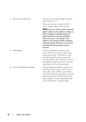
...when using certain operating systems. This button can be pressed using the power button and the system is running an ACPI-compliant operating system, the power is turned off . The power button controls the DC power supply output to do so by qualified support personnel or by the operating ... system performs a graceful shutdown before the power is pushed again. 14 About Your System Use this button only if directed to the system. 1 Power button/indicator. 2 NMI button. 3 System identification button. The power-on indicator lights when the system power is on the back blink until one ...
...when using certain operating systems. This button can be pressed using the power button and the system is running an ACPI-compliant operating system, the power is turned off . The power button controls the DC power supply output to do so by qualified support personnel or by the operating ... system performs a graceful shutdown before the power is pushed again. 14 About Your System Use this button only if directed to the system. 1 Power button/indicator. 2 NMI button. 3 System identification button. The power-on indicator lights when the system power is on the back blink until one ...

Hardware Owner's Manual (PDF)
Page 19
... Features and Indicators 1 2 3 4 5 6 78 12 11 10 9 1 USB connectors (2) 3 Serial connector 5 DRAC network connector 7 System identification button 9 Power supply 11 Power supply lever 2 Video connector 4 Expansion card filler bracket 6 Network connectors (4) 8 Intrusion LED 10 Power connector 12 Power supply latch About Your System 19 For information about enabling, disabling, and configuring I/O ports and connectors, see "Jumpers and...
... Features and Indicators 1 2 3 4 5 6 78 12 11 10 9 1 USB connectors (2) 3 Serial connector 5 DRAC network connector 7 System identification button 9 Power supply 11 Power supply lever 2 Video connector 4 Expansion card filler bracket 6 Network connectors (4) 8 Intrusion LED 10 Power connector 12 Power supply latch About Your System 19 For information about enabling, disabling, and configuring I/O ports and connectors, see "Jumpers and...
Hardware Owner's Manual (PDF)
Page 20
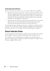
...and Connectors" on the front panel controls the power input to a specific connector and device drivers must be connected to the system's power supplies. Power Indicator Codes The power button on page 153. Table 1-3 lists the power supply indicator codes. 20 About Your System For ...information about individual connectors, see "Using the System Setup Program" on the redundant power supplies show whether power is on ...
...and Connectors" on the front panel controls the power input to a specific connector and device drivers must be connected to the system's power supplies. Power Indicator Codes The power button on page 153. Table 1-3 lists the power supply indicator codes. 20 About Your System For ...information about individual connectors, see "Using the System Setup Program" on the redundant power supplies show whether power is on ...

Hardware Owner's Manual (PDF)
Page 21
Redundant Power Supply Indicators Indicator Power supply status Power supply fault AC line status Function Green indicates that a valid AC source is operational. Green indicates that the power supply is connected to the power supply. About Your System 21 Amber indicates a problem with the power supply. Redundant Power Supply Indicators 1 2 3 1 power supply status 3 AC line status 2 power supply fault Table 1-3. Figure 1-4.
Redundant Power Supply Indicators Indicator Power supply status Power supply fault AC line status Function Green indicates that a valid AC source is operational. Green indicates that the power supply is connected to the power supply. About Your System 21 Amber indicates a problem with the power supply. Redundant Power Supply Indicators 1 2 3 1 power supply status 3 AC line status 2 power supply fault Table 1-3. Figure 1-4.

Hardware Owner's Manual (PDF)
Page 26
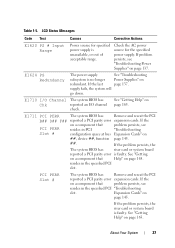
... the AC power source for specified power supply is available from See "Troubleshooting the specified power supply; If problem persists, see "Troubleshooting Power Supplies" on page 165. E1614 PS # Status No power is unavailable, or out of acceptable range; E1421 CPU Init The system BIOS has reported a processor initialization error. Power Supplies" on specified power supply is page 137. Power Supplies" on specified power supply is...
... the AC power source for specified power supply is available from See "Troubleshooting the specified power supply; If problem persists, see "Troubleshooting Power Supplies" on page 165. E1614 PS # Status No power is unavailable, or out of acceptable range; E1421 CPU Init The system BIOS has reported a processor initialization error. Power Supplies" on specified power supply is page 137. Power Supplies" on specified power supply is...
Hardware Owner's Manual (PDF)
Page 27
...component that problem persists, see "Troubleshooting Power Supplies" on redundant. If the problem persists, the riser card or system board is no longer Power Supplies" on page 137. Check the AC power source for specified power supply is faulty. supply fails, the system will go down. ...Troubleshooting Slot # configuration space at bus Expansion Cards" on a component that Help" on page 165. E1624 PS Redundancy The power supply See "Troubleshooting subsystem is faulty. See "Getting on a component that problem persists, see resides in the specified PCI slot...
...component that problem persists, see "Troubleshooting Power Supplies" on redundant. If the problem persists, the riser card or system board is no longer Power Supplies" on page 137. Check the AC power source for specified power supply is faulty. supply fails, the system will go down. ...Troubleshooting Slot # configuration space at bus Expansion Cards" on a component that Help" on page 165. E1624 PS Redundancy The power supply See "Troubleshooting subsystem is faulty. See "Getting on a component that problem persists, see resides in the specified PCI slot...

Hardware Owner's Manual (PDF)
Page 33
... Test Causes Corrective Actions I1911 >3 ERRs Chk Log LCD overflow message. For example, if the code E1418 CPU_1_Presence appears, you might determine that is a failing power supply.
... Test Causes Corrective Actions I1911 >3 ERRs Chk Log LCD overflow message. For example, if the code E1418 CPU_1_Presence appears, you might determine that is a failing power supply.
Hardware Owner's Manual (PDF)
Page 57
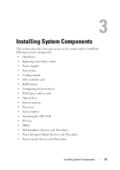
...describes how gain access to the system and to install the following system components: • Hard drives • Replacing a hard drive carrier • Power supplies • System fans • Cooling shroud • SAS controller card • RAID battery • Configuring the boot device • PCI Express ...; Processors • System battery • Activating the NIC TOE • I/O riser • DRAC • SAS backplane (Service-only Procedure) • Power Interposer Board (Service-only Procedure) • System board (Service-only Procedure) Installing System Components 57
...describes how gain access to the system and to install the following system components: • Hard drives • Replacing a hard drive carrier • Power supplies • System fans • Cooling shroud • SAS controller card • RAID battery • Configuring the boot device • PCI Express ...; Processors • System battery • Activating the NIC TOE • I/O riser • DRAC • SAS backplane (Service-only Procedure) • Power Interposer Board (Service-only Procedure) • System board (Service-only Procedure) Installing System Components 57

Hardware Owner's Manual (PDF)
Page 60
... and lays flush on top of the components inside the computer, and protecting against electrostatic discharge. The cover will slide back as a cooling fan or power supply, remove power from the system and attached peripherals, and disconnect the system from the system. See Figure 3-2. 3 Push down the latch to lever the cover into...
... and lays flush on top of the components inside the computer, and protecting against electrostatic discharge. The cover will slide back as a cooling fan or power supply, remove power from the system and attached peripherals, and disconnect the system from the system. See Figure 3-2. 3 Push down the latch to lever the cover into...

Hardware Owner's Manual (PDF)
Page 68
... the system and all attached peripherals. Removing a Power Supply NOTICE: The system requires one power supply installed and without a power supply blank installed for the system to operate normally. Power Supplies Two power supplies power your system has a single power supply, remove power from the power supply. 4 Depress the power supply latch and then pull the power supply lever to extract the power supply out of time can cause the system to...
... the system and all attached peripherals. Removing a Power Supply NOTICE: The system requires one power supply installed and without a power supply blank installed for the system to operate normally. Power Supplies Two power supplies power your system has a single power supply, remove power from the power supply. 4 Depress the power supply latch and then pull the power supply lever to extract the power supply out of time can cause the system to...

Hardware Owner's Manual (PDF)
Page 69
Figure 3-6. Installing System Components 69 See Figure 3-6. 2 Rotate the lever toward the power supply until it is completely flush with the power-supply faceplate and the power supply latch engages. See Figure 3-6. Removing a Power Supply 2 1 43 1 Power supply latch 3 Power connector 2 Power supply lever 4 Power supply status indicators Installing a Power Supply 1 With the power-supply lever in the extended position, slide the new power supply into the chassis.
Figure 3-6. Installing System Components 69 See Figure 3-6. 2 Rotate the lever toward the power supply until it is completely flush with the power-supply faceplate and the power supply latch engages. See Figure 3-6. Removing a Power Supply 2 1 43 1 Power supply latch 3 Power connector 2 Power supply lever 4 Power supply status indicators Installing a Power Supply 1 With the power-supply lever in the extended position, slide the new power supply into the chassis.

Hardware Owner's Manual (PDF)
Page 70
... remove the system cover and access any of the chassis. You can replace each fan housing. NOTE: After installing a new power supply, allow several seconds for complete information about safety precautions, working inside the system. Four cooling fan are authorized to recognize the... power supply and determine whether it is functioning properly. Installing a Front System Fan CAUTION: Only trained service technicians are located at the...
... remove the system cover and access any of the chassis. You can replace each fan housing. NOTE: After installing a new power supply, allow several seconds for complete information about safety precautions, working inside the system. Four cooling fan are authorized to recognize the... power supply and determine whether it is functioning properly. Installing a Front System Fan CAUTION: Only trained service technicians are located at the...
Hardware Owner's Manual (PDF)
Page 135
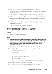
See "Using PowerEdge Diagnostics" on page 60. If the tests fail, see "Getting Help" on page 165. 8 If the system starts properly, shut down the system and reinstall ... cables are properly connected. 4 Close the system. 6 Close the system. Action CAUTION: Only trained service technicians are properly installed: • Expansion cards and risers • Power supplies • Fans • Processors and processor heat sinks • Memory modules • Drive-carrier connections to the electrical outlet, and turn on page 86. 9 Run...
See "Using PowerEdge Diagnostics" on page 60. If the tests fail, see "Getting Help" on page 165. 8 If the system starts properly, shut down the system and reinstall ... cables are properly connected. 4 Close the system. 6 Close the system. Action CAUTION: Only trained service technicians are properly installed: • Expansion cards and risers • Power supplies • Fans • Processors and processor heat sinks • Memory modules • Drive-carrier connections to the electrical outlet, and turn on page 86. 9 Run...


