Information Update
Page 1
... BMC or the DRAC5, you must update the firmware for 8-GB Memory Modules Your Dell™ PowerEdge™ R900 system now supports the following 8-GB memory configurations: • 32 GB - 4 x 8-GB quad-rank memory modules • 64 GB - 8 x 8-GB quad-rank memory modules NOTE: If 64 GB of memory is installed, the system will ensure that your system. For...
... BMC or the DRAC5, you must update the firmware for 8-GB Memory Modules Your Dell™ PowerEdge™ R900 system now supports the following 8-GB memory configurations: • 32 GB - 4 x 8-GB quad-rank memory modules • 64 GB - 8 x 8-GB quad-rank memory modules NOTE: If 64 GB of memory is installed, the system will ensure that your system. For...
Getting Started Guide
Page 5
... DVD-ROM/CD-RW drive or slimline SATA DVD-ROM/CD-RW drive (when available). • Two hot-pluggable power supplies in a 1 + 1 redundant configuration. • Four fan modules, each comprised of two dual-rotor fans, for a total of eight cooling fans. • Three x4 and four x8 PCI... 100-Mbps, and 1000-Mbps data rates. • Dedicated PCI slot for the latest support information about booting from Dell. The upgrade kit from Dell contains the correct version of cache memory and a RAID battery. Getting Started With Your System 3 Not all versions of this feature, you must use an ...
... DVD-ROM/CD-RW drive or slimline SATA DVD-ROM/CD-RW drive (when available). • Two hot-pluggable power supplies in a 1 + 1 redundant configuration. • Four fan modules, each comprised of two dual-rotor fans, for a total of eight cooling fans. • Three x4 and four x8 PCI... 100-Mbps, and 1000-Mbps data rates. • Dedicated PCI slot for the latest support information about booting from Dell. The upgrade kit from Dell contains the correct version of cache memory and a RAID battery. Getting Started With Your System 3 Not all versions of this feature, you must use an ...
Hardware Owner's Manual (PDF)
Page 4
Responding to Error Messages 41 Using the System Setup Program 42 System Setup Options 43 Main Screen 43 Memory Information Screen 45 CPU Information Screen 45 Integrated Devices Screen 46 PCI IRQ Screen 47 Serial Communication Screen 47 Embedded Server ...Screen 49 System and Setup Password Features 49 Using the System Password 50 Using the Setup Password 53 Disabling a Forgotten Password 54 Baseboard Management Controller Configuration . . . 54 Entering the BMC Setup Module 55 BMC Setup Module Options 55 3 Installing System Components 57 Recommended Tools 58 Inside the System...
Responding to Error Messages 41 Using the System Setup Program 42 System Setup Options 43 Main Screen 43 Memory Information Screen 45 CPU Information Screen 45 Integrated Devices Screen 46 PCI IRQ Screen 47 Serial Communication Screen 47 Embedded Server ...Screen 49 System and Setup Password Features 49 Using the System Password 50 Using the Setup Password 53 Disabling a Forgotten Password 54 Baseboard Management Controller Configuration . . . 54 Entering the BMC Setup Module 55 BMC Setup Module Options 55 3 Installing System Components 57 Recommended Tools 58 Inside the System...

Hardware Owner's Manual (PDF)
Page 6
Removing a RAID Battery 85 Configuring the Boot Device 86 PCI Express Add-in Cards 86 Installing a PCI Express Card 86 Removing a PCI Express Card 88 Optical Drive 88 ... Into an Optical Drive Mounting Tray 92 System Memory 92 General Memory Module Installation Guidelines . 92 Non-Optimal Memory Configurations 93 Memory Sparing Support 93 Memory Mirroring Support 94 Removing a Memory Riser 96 Installing a Memory Riser 98 Memory Population Rules 98 Removing the Memory Riser Cover 99 Installing Memory Modules 99 Removing Memory Modules 101 Processors 101 Removing a Processor Heat ...
Removing a RAID Battery 85 Configuring the Boot Device 86 PCI Express Add-in Cards 86 Installing a PCI Express Card 86 Removing a PCI Express Card 88 Optical Drive 88 ... Into an Optical Drive Mounting Tray 92 System Memory 92 General Memory Module Installation Guidelines . 92 Non-Optimal Memory Configurations 93 Memory Sparing Support 93 Memory Mirroring Support 94 Removing a Memory Riser 96 Installing a Memory Riser 98 Memory Population Rules 98 Removing the Memory Riser Cover 99 Installing Memory Modules 99 Removing Memory Modules 101 Processors 101 Removing a Processor Heat ...

Hardware Owner's Manual (PDF)
Page 29
... the cable. Table 1-5. Reseat the cable. See "SAS Controller Card" on page 139. Error detected during memory configuration. page 139. Memory System Memory" on page 78. E2011 Mem Config Error Memory detected, but See "Troubleshooting not usable. Install memory. See "SAS Controller Card" on subsystem failure. If problem persists, replace cable. Update to See "Troubleshooting Fail...
... the cable. Table 1-5. Reseat the cable. See "SAS Controller Card" on page 139. Error detected during memory configuration. page 139. Memory System Memory" on page 78. E2011 Mem Config Error Memory detected, but See "Troubleshooting not usable. Install memory. See "SAS Controller Card" on subsystem failure. If problem persists, replace cable. Update to See "Troubleshooting Fail...

Hardware Owner's Manual (PDF)
Page 31
... Status Messages Code Test Causes Corrective Actions E201F DRAC Config Dell Remote Assistant Card (DRAC) configuration failure. Check screen for specific configuration. multi-bit error (MBE). Ensure that DRAC cables and connectors are properly seated. Check screen for specific error messages. If no memory riser card is present, the "Crd #" string is rebooted. About...
... Status Messages Code Test Causes Corrective Actions E201F DRAC Config Dell Remote Assistant Card (DRAC) configuration failure. Check screen for specific configuration. multi-bit error (MBE). Ensure that DRAC cables and connectors are properly seated. Check screen for specific error messages. If no memory riser card is present, the "Crd #" string is rebooted. About...
Hardware Owner's Manual (PDF)
Page 34
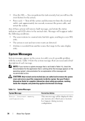
... The system is reset and new error events are authorized to remove the system cover and access any memory error which causes memory loss happens during memory configuration. 34 About Your System System Messages System messages appear on the screen to the normal state. wait ...system's documentation for the system. • Power cycle - • Clear the SEL - System Messages System Message Error: Incorrect memory configuration. Messages will lose the event history for an explanation of the components inside the computer, and protecting against electrostatic discharge. You can...
... The system is reset and new error events are authorized to remove the system cover and access any memory error which causes memory loss happens during memory configuration. 34 About Your System System Messages System messages appear on the screen to the normal state. wait ...system's documentation for the system. • Power cycle - • Clear the SEL - System Messages System Message Error: Incorrect memory configuration. Messages will lose the event history for an explanation of the components inside the computer, and protecting against electrostatic discharge. You can...

Hardware Owner's Manual (PDF)
Page 35
... more DIMMs improperly seated or faulty Diskette drive 0 seek failure Faulty or improperly inserted diskette, incorrect configuration settings in diskette drive About Your System 35 Redundant memory was set to enabled in CMOS, but the memory configuration is not validated. Table 1-6. System Messages System Message Corrective Action Warning: The current memory configuration is not recommended by Dell.
... more DIMMs improperly seated or faulty Diskette drive 0 seek failure Faulty or improperly inserted diskette, incorrect configuration settings in diskette drive About Your System 35 Redundant memory was set to enabled in CMOS, but the memory configuration is not validated. Table 1-6. System Messages System Message Corrective Action Warning: The current memory configuration is not recommended by Dell.

Hardware Owner's Manual (PDF)
Page 37
... Memory tests terminated by keystroke POST memory test terminated by pressing the No boot device available Faulty diskette, diskette/tape drive subsystem, hard-disk drive, hard-disk drive subsystem, or no boot disk in drive A No boot sector on hard-disk drive Incorrect configuration ...diskette PCI BIOS failed to installed PCI device BIOS (Option ROM) checksum failure is detected during shadowing Plug & Play Configuration error Plug & Play Configuration error is detected during PCI device scan Read fault Requested sector not found Faulty diskette, diskette/tape drive subsystem, ...
... Memory tests terminated by keystroke POST memory test terminated by pressing the No boot device available Faulty diskette, diskette/tape drive subsystem, hard-disk drive, hard-disk drive subsystem, or no boot disk in drive A No boot sector on hard-disk drive Incorrect configuration ...diskette PCI BIOS failed to installed PCI device BIOS (Option ROM) checksum failure is detected during shadowing Plug & Play Configuration error Plug & Play Configuration error is detected during PCI device scan Read fault Requested sector not found Faulty diskette, diskette/tape drive subsystem, ...

Hardware Owner's Manual (PDF)
Page 44
...IRQ assignments. Set up the processor configuration. See "Embedded Server Management Screen" on page 45. See "CPU Information Screen" on page 47. See "PCI IRQ Screen" on page 45. System Setup Program Options Option System Time System Date Memory Information CPU Information Boot Sequence USB Flash...Errors Description Set up the system time Set up the system date Set up the system security. Set up the memory configuration. See "System Security Screen" on the system configuration. Set up the boot device sequence Set up Virtual Floppy as Auto / Floppy / Hard disk Enabled / ...
...IRQ assignments. Set up the processor configuration. See "Embedded Server Management Screen" on page 45. See "CPU Information Screen" on page 47. See "PCI IRQ Screen" on page 45. System Setup Program Options Option System Time System Date Memory Information CPU Information Boot Sequence USB Flash...Errors Description Set up the system time Set up the system date Set up the system security. Set up the memory configuration. See "System Security Screen" on the system configuration. Set up the boot device sequence Set up Virtual Floppy as Auto / Floppy / Hard disk Enabled / ...
Hardware Owner's Manual (PDF)
Page 57
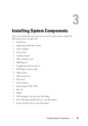
... carrier • Power supplies • System fans • Cooling shroud • SAS controller card • RAID battery • Configuring the boot device • PCI Express add-in cards • Optical drive • System memory • Processors • System battery • Activating the NIC TOE • I/O riser • DRAC • SAS backplane (Service...
... carrier • Power supplies • System fans • Cooling shroud • SAS controller card • RAID battery • Configuring the boot device • PCI Express add-in cards • Optical drive • System memory • Processors • System battery • Activating the NIC TOE • I/O riser • DRAC • SAS backplane (Service...
Hardware Owner's Manual (PDF)
Page 92
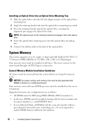
... Slide the optical drive onto the left side alignment pins of the optical drive. Four memory risers must be removed from the system before servicing the memory risers. General Memory Module Installation Guidelines AC power must be installed starting with one DIMM per riser must engage... bracket must be installed at all times. The risers connect to match DIMMs between different slot numbers. 92 Installing System Components Supported memory riser configurations are as follows: • All DIMMs must match (size, technology, etc.). or dual-rank fully buffered 667 MT/s (55...
... Slide the optical drive onto the left side alignment pins of the optical drive. Four memory risers must be removed from the system before servicing the memory risers. General Memory Module Installation Guidelines AC power must be installed starting with one DIMM per riser must engage... bracket must be installed at all times. The risers connect to match DIMMs between different slot numbers. 92 Installing System Components Supported memory riser configurations are as follows: • All DIMMs must match (size, technology, etc.). or dual-rank fully buffered 667 MT/s (55...
Hardware Owner's Manual (PDF)
Page 93
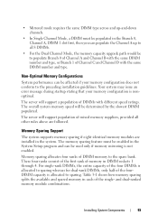
.... Your system may issue an error message during startup stating that your memory configuration does not conform to sparing whereas for dual-rank DIMMs, only half of the single- The memory sparing feature must be populated in each of the fourDIMM capacity is allocated...in DIMM sockets 1 through 4. Non-Optimal Memory Configurations System performance can be used only if memory mirroring is nonoptimal. The overall system memory speed will support population of memory in the system. The server will be affected if your memory configuration is not enabled. These four ranks consist...
.... Your system may issue an error message during startup stating that your memory configuration does not conform to sparing whereas for dual-rank DIMMs, only half of the single- The memory sparing feature must be populated in each of the fourDIMM capacity is allocated...in DIMM sockets 1 through 4. Non-Optimal Memory Configurations System performance can be used only if memory mirroring is nonoptimal. The overall system memory speed will support population of memory in the system. The server will be affected if your memory configuration is not enabled. These four ranks consist...

Hardware Owner's Manual (PDF)
Page 94
... is one-half of Channel 0 Channel 1 Channel 2 Channel 3 Available Redundant DIMMS (Riser A) (Riser B) (Riser C) (Riser D) Memory Modes 1 DIMM A1 (riser only) (riser only) (riser only) None 4 DIMM A1 DIMM B1 DIMM C1 DIMM D1 None 8 DIMM A1 DIMM B1 DIMM C1 ... C3 DIMM D3 DIMM A4 DIMM B4 DIMM C4 DIMM D4 DIMM A5 DIMM B5 DIMM C5 DIMM D5 94 Installing System Components In a mirrored configuration, the total available system memory is not enabled. Valid Memory Configurations Branch 0 Branch 1 Number of the total installed memory. Mirroring must be enabled in the system.
... is one-half of Channel 0 Channel 1 Channel 2 Channel 3 Available Redundant DIMMS (Riser A) (Riser B) (Riser C) (Riser D) Memory Modes 1 DIMM A1 (riser only) (riser only) (riser only) None 4 DIMM A1 DIMM B1 DIMM C1 DIMM D1 None 8 DIMM A1 DIMM B1 DIMM C1 ... C3 DIMM D3 DIMM A4 DIMM B4 DIMM C4 DIMM D4 DIMM A5 DIMM B5 DIMM C5 DIMM D5 94 Installing System Components In a mirrored configuration, the total available system memory is not enabled. Valid Memory Configurations Branch 0 Branch 1 Number of the total installed memory. Mirroring must be enabled in the system.

Hardware Owner's Manual (PDF)
Page 95
Valid Memory Configurations Branch 0 Branch 1 Number of Channel 0 Channel 1 Channel 2 Channel 3 Available Redundant DIMMS (Riser A) (Riser B) (Riser C) (Riser D) Memory Modes 24 DIMM A1 DIMM B1 DIMM C1 DIMM D1 Spare Mode / Mirror DIMM A2 DIMM B2 DIMM C2 DIMM D2 Mode DIMM A3 DIMM ... B6 DIMM C6 DIMM D6 DIMM A7 DIMM B7 DIMM C7 DIMM D7 DIMM A8 DIMM B8 DIMM C8 DIMM D8 NOTE: The single DIMM configuration is for troubleshooting. Installing System Components 95 Table 3-1.
Valid Memory Configurations Branch 0 Branch 1 Number of Channel 0 Channel 1 Channel 2 Channel 3 Available Redundant DIMMS (Riser A) (Riser B) (Riser C) (Riser D) Memory Modes 24 DIMM A1 DIMM B1 DIMM C1 DIMM D1 Spare Mode / Mirror DIMM A2 DIMM B2 DIMM C2 DIMM D2 Mode DIMM A3 DIMM ... B6 DIMM C6 DIMM D6 DIMM A7 DIMM B7 DIMM C7 DIMM D7 DIMM A8 DIMM B8 DIMM C8 DIMM D8 NOTE: The single DIMM configuration is for troubleshooting. Installing System Components 95 Table 3-1.
Hardware Owner's Manual (PDF)
Page 101
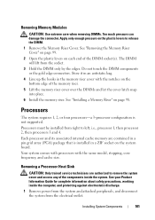
...protecting against electrostatic discharge. 1 Remove power from the system and attached peripherals, and disconnect the system from the electrical outlet. Removing Memory Modules CAUTION: Use extreme care when removing DIMMs. Too much pressure can damage the connector. Store it in an antistatic bag. ...up the hooks in a ZIF socket on the system board. Processors The system requires 1, 2, or four processors-a 3-processor configuration is installed in the memory riser cover with the same model, stepping, core frequency, and cache size. Your system comes with processors with the notches on...
...protecting against electrostatic discharge. 1 Remove power from the system and attached peripherals, and disconnect the system from the electrical outlet. Removing Memory Modules CAUTION: Use extreme care when removing DIMMs. Too much pressure can damage the connector. Store it in an antistatic bag. ...up the hooks in a ZIF socket on the system board. Processors The system requires 1, 2, or four processors-a 3-processor configuration is installed in the memory riser cover with the same model, stepping, core frequency, and cache size. Your system comes with processors with the notches on...

Hardware Owner's Manual (PDF)
Page 108
See "Removing the Top Cover" on page 60. 3 Remove memory risers 3 and 4 from the electrical outlet. 2 Open the system. See "System Board Connectors" on the system board. Ensure that the object is inserted between the ... Diagnostics" on page 43. 13 Run the system diagnostics to enter the System Setup program, and check that the processor information matches the new system configuration. Replacing the System Battery CAUTION: Only trained service technicians are authorized to remove the system cover and access any attached peripherals, and disconnect the system...
See "Removing the Top Cover" on page 60. 3 Remove memory risers 3 and 4 from the electrical outlet. 2 Open the system. See "System Board Connectors" on the system board. Ensure that the object is inserted between the ... Diagnostics" on page 43. 13 Run the system diagnostics to enter the System Setup program, and check that the processor information matches the new system configuration. Replacing the System Battery CAUTION: Only trained service technicians are authorized to remove the system cover and access any attached peripherals, and disconnect the system...

Hardware Owner's Manual (PDF)
Page 140
...page 96. 7 Remove the memory riser covers. NOTE: Several configurations for memory modules exist; See "Removing a Memory Riser" on page 98. 11 Close the system. See "Installing Memory Modules" on page 92. see "General Memory Module Installation Guidelines" on page 99 9 Install the memory riser cover.s. f As ...on page 99. See "Using the System Setup Program" on page 99. 8 Reseat the memory modules in socket 1 with another of memory installed does not match the system memory setting, then perform the following steps: a Remove power from the system and attached peripherals, and...
...page 96. 7 Remove the memory riser covers. NOTE: Several configurations for memory modules exist; See "Removing a Memory Riser" on page 98. 11 Close the system. See "Installing Memory Modules" on page 92. see "General Memory Module Installation Guidelines" on page 99 9 Install the memory riser cover.s. f As ...on page 99. See "Using the System Setup Program" on page 99. 8 Reseat the memory modules in socket 1 with another of memory installed does not match the system memory setting, then perform the following steps: a Remove power from the system and attached peripherals, and...

Hardware Owner's Manual (PDF)
Page 171
... a hard drive. Alternating current. ANSI - A battery that clears all memory, initializes devices, and loads the operating system when you can reboot (also called warm boot) your system by your operating system. A standard interface for security or tracking purposes. Software designed to direct configuration and power management. The BIOS controls communications between the...
... a hard drive. Alternating current. ANSI - A battery that clears all memory, initializes devices, and loads the operating system when you can reboot (also called warm boot) your system by your operating system. A standard interface for security or tracking purposes. Software designed to direct configuration and power management. The BIOS controls communications between the...

Hardware Owner's Manual (PDF)
Page 173
... branch off them. Some device drivers-such as memory-resident programs (usually, from the config.sys file or as network drivers-must load when you to a client system. Dynamic Host Configuration Protocol. Dual in a hierarchical, "inverted tree..." structure. Deutsche Industrie Norm. A DMA channel allows certain types of tests for which they were designed. A system's RAM is usually made up entirely of translating Internet domain names, such as www.dell.com, into IP addresses, such as the operating system, memory...
... branch off them. Some device drivers-such as memory-resident programs (usually, from the config.sys file or as network drivers-must load when you to a client system. Dynamic Host Configuration Protocol. Dual in a hierarchical, "inverted tree..." structure. Deutsche Industrie Norm. A DMA channel allows certain types of tests for which they were designed. A system's RAM is usually made up entirely of translating Internet domain names, such as www.dell.com, into IP addresses, such as the operating system, memory...


