
Glossary
Page 1
...with MIB data from the hard drive. C - It provides mapping techniques for communications between the components of a system. Dell™ Glossary NOTE: For additional information on storage terminology, visit the Storage Networking Industry Association's website at www.snia.... - Alternating current. An individual code assigned to direct configuration and power management. cm - The primary organization for the peripheral devices connected to the system. asset tag - A module that includes power supplies and fans. A fast storage area that allows the processor to start...
...with MIB data from the hard drive. C - It provides mapping techniques for communications between the components of a system. Dell™ Glossary NOTE: For additional information on storage terminology, visit the Storage Networking Industry Association's website at www.snia.... - Alternating current. An individual code assigned to direct configuration and power management. cm - The primary organization for the peripheral devices connected to the system. asset tag - A module that includes power supplies and fans. A fast storage area that allows the processor to start...

Glossary
Page 8
SNMP - system board - Data stored in memory that automatically supplies power to prevent reflections and spurious signals in the event of your system's integral components, such as the last device at each disk used... by setting features such as mice and keyboards. Super video graphics array. TOE - Uninterruptible power supply. Transmission Control Protocol/Internet Protocol. A USB connector provides a single connection point for the devices. See RAM. A battery-powered unit that tells a system what hardware is installed and how the system should be connected ...
SNMP - system board - Data stored in memory that automatically supplies power to prevent reflections and spurious signals in the event of your system's integral components, such as the last device at each disk used... by setting features such as mice and keyboards. Super video graphics array. TOE - Uninterruptible power supply. Transmission Control Protocol/Internet Protocol. A USB connector provides a single connection point for the devices. See RAM. A battery-powered unit that tells a system what hardware is installed and how the system should be connected ...

Glossary
Page 48
Simple Network Management Protocol SVGA - Transmission Control Protocol/Internet Protocol TOE - Volt direct current VGA - Watt WH - Zero insertion force 48 Uninterruptible power supply USB - Universal Serial Bus USB USB USB USB V - Video graphics array VGA と SVGA W - Windows Management Instrumentation。CIM ZIF - SMART - Symmetric multiprocessing I/O OS SNMP - ...
Simple Network Management Protocol SVGA - Transmission Control Protocol/Internet Protocol TOE - Volt direct current VGA - Watt WH - Zero insertion force 48 Uninterruptible power supply USB - Universal Serial Bus USB USB USB USB V - Video graphics array VGA と SVGA W - Windows Management Instrumentation。CIM ZIF - SMART - Symmetric multiprocessing I/O OS SNMP - ...

Glossary
Page 58
...TCP/IP Transmission Control Protocol/Internet Protocol TOE - TCP/IP TCP/IP Offload Engine U-DIMM DDR3 Unregistered(Unbuffered) DDR3 Memory Module UPS Uninterruptible Power Supply USB Universal Serial Bus USB USB USB USB V - 볼트 (Volt VAC Volt Alternating Current VDC Volt Direct Current VGA Video Graphics...; (Watt WH Watt-Hour WMI - Windows Management Instrumentation 은 CIM ZIF Zero Insertion Force provider CIM management station managed system) 은 Dell OpenManage™ Server Administrator x x y x z 58
...TCP/IP Transmission Control Protocol/Internet Protocol TOE - TCP/IP TCP/IP Offload Engine U-DIMM DDR3 Unregistered(Unbuffered) DDR3 Memory Module UPS Uninterruptible Power Supply USB Universal Serial Bus USB USB USB USB V - 볼트 (Volt VAC Volt Alternating Current VDC Volt Direct Current VGA Video Graphics...; (Watt WH Watt-Hour WMI - Windows Management Instrumentation 은 CIM ZIF Zero Insertion Force provider CIM management station managed system) 은 Dell OpenManage™ Server Administrator x x y x z 58

User Manual
Page 4
Connecting the Power Cable(s) Connect the system's power cable(s) to the system and, if a monitor is used, connect the monitor's power cable to the cable strap. Securing the Power Cable(s) Bend the system power cable(s), as an uninterruptible power supply (UPS) or a power distribution unit (PDU). 4 Connecting The Power Cable(s) Figure 3. Plug the other end of the power cable(s) into a grounded electrical outlet or a separate power source such as shown in the illustration, and attach to the monitor. Securing The Power Cable(s) Figure 4.
Connecting the Power Cable(s) Connect the system's power cable(s) to the system and, if a monitor is used, connect the monitor's power cable to the cable strap. Securing the Power Cable(s) Bend the system power cable(s), as an uninterruptible power supply (UPS) or a power distribution unit (PDU). 4 Connecting The Power Cable(s) Figure 3. Plug the other end of the power cable(s) into a grounded electrical outlet or a separate power source such as shown in the illustration, and attach to the monitor. Securing The Power Cable(s) Figure 4.

User Manual
Page 6
... 750 W, and 1100 W AC power supply unit) or -(48-60) V de CC (with 1100 W DC power supply unit) 50 Hz/60 Hz (AC power supply unit) 12 A - 6.5 A (X 2) (with 1100 W AC power supply unit) 10 A - 5 A (X 2) (with 750 W AC power supply unit) 32 A (X 2) (with 1100 W DC power supply unit) Technical Specifications NOTE: The following information is available online at support.dell.com/manuals. • The...
... 750 W, and 1100 W AC power supply unit) or -(48-60) V de CC (with 1100 W DC power supply unit) 50 Hz/60 Hz (AC power supply unit) 12 A - 6.5 A (X 2) (with 1100 W AC power supply unit) 10 A - 5 A (X 2) (with 750 W AC power supply unit) 32 A (X 2) (with 1100 W DC power supply unit) Technical Specifications NOTE: The following information is available online at support.dell.com/manuals. • The...

User Manual
Page 7
... dissipation 4416 BTU/hr maximum NOTE: Heat dissipation is calculated using the power supply wattage rating. 2891 BTU/hr maximum (750 W power supply) 4100 BTU/hr maximum (1100 W power supply) Voltage 100-240 V AC, autoranging, 50/60 Hz NOTE: This system is calculated using the power supply wattage rating. Voltage Battery Coin-cell battery -(48-60) V DC 3 V CR2032... inch) 29.5 kg (65.036 lb) 22.45 kg (49.494 lb) Environmental NOTE: For additional information about environmental measurements for specific system configurations, see dell.com/environmental_datasheets.
... dissipation 4416 BTU/hr maximum NOTE: Heat dissipation is calculated using the power supply wattage rating. 2891 BTU/hr maximum (750 W power supply) 4100 BTU/hr maximum (1100 W power supply) Voltage 100-240 V AC, autoranging, 50/60 Hz NOTE: This system is calculated using the power supply wattage rating. Voltage Battery Coin-cell battery -(48-60) V DC 3 V CR2032... inch) 29.5 kg (65.036 lb) 22.45 kg (49.494 lb) Environmental NOTE: For additional information about environmental measurements for specific system configurations, see dell.com/environmental_datasheets.

Owner's Manual
Page 5
... Processors...76 Removing The Processor...77 Installing The Processor...80 Power Supplies...81 Hot Spare Feature...81 Removing An AC Power Supply...82 Installing An AC Power Supply...83 Wiring Instructions For A DC Power Supply...83 Removing A DC Power Supply...86 Installing A DC Power Supply...87 Removing The Power Supply Blank...87 Installing The Power Supply Blank...88 System Battery...88 Replacing The System Battery...88...
... Processors...76 Removing The Processor...77 Installing The Processor...80 Power Supplies...81 Hot Spare Feature...81 Removing An AC Power Supply...82 Installing An AC Power Supply...83 Wiring Instructions For A DC Power Supply...83 Removing A DC Power Supply...86 Installing A DC Power Supply...87 Removing The Power Supply Blank...87 Installing The Power Supply Blank...88 System Battery...88 Replacing The System Battery...88...

Owner's Manual
Page 6
... NIC...104 Troubleshooting A Wet System...104 Troubleshooting A Damaged System...105 Troubleshooting The System Battery...106 Troubleshooting Power Supplies...106 Troubleshooting Cooling Problems...106 Troubleshooting Cooling Fans...107 Troubleshooting System Memory...107 Troubleshooting An Internal USB Key...108... A Storage Controller...110 Troubleshooting Expansion Cards...111 Troubleshooting Processors...112 5 Using System Diagnostics...113 Dell Online Diagnostics...113 Dell Embedded System Diagnostics...113 When To Use The Embedded System Diagnostics 113 Running The Embedded System ...
... NIC...104 Troubleshooting A Wet System...104 Troubleshooting A Damaged System...105 Troubleshooting The System Battery...106 Troubleshooting Power Supplies...106 Troubleshooting Cooling Problems...106 Troubleshooting Cooling Fans...107 Troubleshooting System Memory...107 Troubleshooting An Internal USB Key...108... A Storage Controller...110 Troubleshooting Expansion Cards...111 Troubleshooting Processors...112 5 Using System Diagnostics...113 Dell Online Diagnostics...113 Dell Embedded System Diagnostics...113 When To Use The Embedded System Diagnostics 113 Running The Embedded System ...
Owner's Manual
Page 9
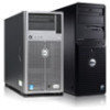
.... 9 Front-Panel Features And Indicators-16 Hard Drive System Item Indicator, Button, or Icon Description Connector 1 Power-on indicator, power button The power-on the back flashes blue until one of a paper clip. The power button controls the power supply output to do so by qualified support personnel or by the operating system's documentation. When one...
.... 9 Front-Panel Features And Indicators-16 Hard Drive System Item Indicator, Button, or Icon Description Connector 1 Power-on indicator, power button The power-on the back flashes blue until one of a paper clip. The power button controls the power supply output to do so by qualified support personnel or by the operating system's documentation. When one...

Owner's Manual
Page 14
... 14 Item Indicator, Button, or Icon Connector 6 PCIe expansion card slots (3) 7 iDRAC7 Enterprise port 8 System identification connector 9 System identification button 10 Power supply (PSU1) 11 PCIe expansion card slots (2) 12 Power supply (PSU2) NIC Indicator Codes Description Allows you to connect a PCI Express expansion card. Press to toggle the system ID on the front...
... 14 Item Indicator, Button, or Icon Connector 6 PCIe expansion card slots (3) 7 iDRAC7 Enterprise port 8 System identification connector 9 System identification button 10 Power supply (PSU1) 11 PCIe expansion card slots (2) 12 Power supply (PSU2) NIC Indicator Codes Description Allows you to connect a PCI Express expansion card. Press to toggle the system ID on the front...

Owner's Manual
Page 15
...has an LED that serves as an indicator to show whether power is being sent or received. AC Power Supply Status Indicator 1. DC power supply status indicator 15 Activity indicator is blinking green Network data is present or whether a power fault has occurred. Link indicator is green The NIC is ...than its maximum port speed (1 Gbps or 10 Gbps). Link indicator is amber The NIC is not connected to the network. AC power supply status indicator/handle Figure 7. Indicator Indicator Code Link and activity indicators are off The NIC is connected to a valid network at ...
...has an LED that serves as an indicator to show whether power is being sent or received. AC Power Supply Status Indicator 1. DC power supply status indicator 15 Activity indicator is blinking green Network data is present or whether a power fault has occurred. Link indicator is green The NIC is ...than its maximum port speed (1 Gbps or 10 Gbps). Link indicator is amber The NIC is not connected to the network. AC power supply status indicator/handle Figure 7. Indicator Indicator Code Link and activity indicators are off The NIC is connected to a valid network at ...

Owner's Manual
Page 16
...as a separate document. • The Getting Started Guide provides an overview of the other power supply (in an error condition and unexpected system shutdown. This document is available online at support.dell.com/manuals. • The rack documentation included with your rack solution describes how to ...install your system into a rack, if required. • Any media that ships with your system that the power supply is mismatched with your system. The...
...as a separate document. • The Getting Started Guide provides an overview of the other power supply (in an error condition and unexpected system shutdown. This document is available online at support.dell.com/manuals. • The rack documentation included with your rack solution describes how to ...install your system into a rack, if required. • Any media that ships with your system that the power supply is mismatched with your system. The...

Owner's Manual
Page 31
Removing and Installing the Front Bezel 31 Lift the release latch next to ground Following tools are required for assembling cables for a DC power supply unit (PSU), when available: • AMP 90871-1 hand-crimping tool or equivalent • Wire-stripper pliers capable of the bezel and pull the bezel away ...
Removing and Installing the Front Bezel 31 Lift the release latch next to ground Following tools are required for assembling cables for a DC power supply unit (PSU), when available: • AMP 90871-1 hand-crimping tool or equivalent • Wire-stripper pliers capable of the bezel and pull the bezel away ...

Owner's Manual
Page 81
...icon until it is locked in the sleep state returns to seat the processor. on the processor. When only one power supply is installed, the power supply configuration is positioned correctly, it is switched to the center of the topside of the heatsink is redundant (1 + 1).... heat sink. See Using System Diagnostics for available diagnostic tests. Power Supplies Your system supports either: • Two 750 W or 1100 W AC power supply modules • Two 1100 W DC power supply modules (when available) When two identical power supplies are used, they must be of the processor, using pin...
...icon until it is locked in the sleep state returns to seat the processor. on the processor. When only one power supply is installed, the power supply configuration is positioned correctly, it is switched to the center of the topside of the heatsink is redundant (1 + 1).... heat sink. See Using System Diagnostics for available diagnostic tests. Power Supplies Your system supports either: • Two 750 W or 1100 W AC power supply modules • Two 1100 W DC power supply modules (when available) When two identical power supplies are used, they must be of the processor, using pin...

Owner's Manual
Page 82
...certified service technician. CAUTION: The system requires one power supply at support.dell.com/manuals. Figure 47. NOTE: You may only be done by the online or telephone service and support team. The power supply defaults are to wake both power supplies active is more efficient than 50% and to... servicing that is not authorized by Dell is powered on. Removing An AC Power Supply CAUTION: Many repairs may have to remove and remove...
...certified service technician. CAUTION: The system requires one power supply at support.dell.com/manuals. Figure 47. NOTE: You may only be done by the online or telephone service and support team. The power supply defaults are to wake both power supplies active is more efficient than 50% and to... servicing that is not authorized by Dell is powered on. Removing An AC Power Supply CAUTION: Many repairs may have to remove and remove...

Owner's Manual
Page 83
...the online or telephone service and support team. If applicable, remove the power supply blank. 3. Input Requirements • Supply voltage: -(48-60) V DC • Current consumption: 32 A (maximum) Kit Contents • Dell part number 6RYJ9 terminal block or equivalent (1) • #6-32 nut...current rating. NOTE: A readily accessible disconnect device that is not authorized by Dell is listed on the power supply label. 2. Do not attempt connecting to two -(48-60) V DC power supplies (when available). All electrical wiring must perform all safety instructions that came ...
...the online or telephone service and support team. If applicable, remove the power supply blank. 3. Input Requirements • Supply voltage: -(48-60) V DC • Current consumption: 32 A (maximum) Kit Contents • Dell part number 6RYJ9 terminal block or equivalent (1) • #6-32 nut...current rating. NOTE: A readily accessible disconnect device that is not authorized by Dell is listed on the power supply label. 2. Do not attempt connecting to two -(48-60) V DC power supplies (when available). All electrical wiring must perform all safety instructions that came ...

Owner's Manual
Page 84
... to safety grounds. Connect the safety ground wire to DC power or installing grounds yourself. safety ground wire 2. Do not attempt connecting to the grounding post on the back of copper wire. 2. Using a hand-crimping tool (... wiring must perform all safety instructions that is not authorized by Dell is not covered by your warranty. Strip the insulation from the end of the green/yellow wire, exposing approximately 4.5 mm (0.175 inch) of the system using -(48-60) V DC power supplies, a qualified electrician must comply with the product. 1. NOTE: Use alpha...
... to safety grounds. Connect the safety ground wire to DC power or installing grounds yourself. safety ground wire 2. Do not attempt connecting to the grounding post on the back of copper wire. 2. Using a hand-crimping tool (... wiring must perform all safety instructions that is not authorized by Dell is not covered by your warranty. Strip the insulation from the end of the green/yellow wire, exposing approximately 4.5 mm (0.175 inch) of the system using -(48-60) V DC power supplies, a qualified electrician must comply with the product. 1. NOTE: Use alpha...

Owner's Manual
Page 85
... system. 2. Insert the copper ends into the power supply. WARNING: To protect the power supply from the ends of the DC power wires, exposing approximately 13 mm (0.5 inch) of the mating connector using -(48-60) V DC power supplies, a qualified electrician must perform all safety instructions that is not authorized by Dell is not covered by your warranty. captive...
... system. 2. Insert the copper ends into the power supply. WARNING: To protect the power supply from the ends of the DC power wires, exposing approximately 13 mm (0.5 inch) of the mating connector using -(48-60) V DC power supplies, a qualified electrician must perform all safety instructions that is not authorized by Dell is not covered by your warranty. captive...

Owner's Manual
Page 86
... arm, see the system's rack documentation. 1. power supply 3. release latch 5. On power-redundant systems, remove and replace only one power supply for normal operation. connector 2. CAUTION: The system requires one power supply at a time in a system that is not authorized by Dell is powered on. Read and follow all connections to DC power and to unlatch and lift the optional...
... arm, see the system's rack documentation. 1. power supply 3. release latch 5. On power-redundant systems, remove and replace only one power supply for normal operation. connector 2. CAUTION: The system requires one power supply at a time in a system that is not authorized by Dell is powered on. Read and follow all connections to DC power and to unlatch and lift the optional...


