
Glossary
Page 2
... controls, such as NICs. A math coprocessor, for the serial ports on both the rising and falling pulses of tests for peripherals, such as the power button and power indicator. Digital versatile disc or digital video disc. The part of automatically assigning an IP address to interface correctly with controllers for your network server...
... controls, such as NICs. A math coprocessor, for the serial ports on both the rising and falling pulses of tests for peripherals, such as the power button and power indicator. Digital versatile disc or digital video disc. The part of automatically assigning an IP address to interface correctly with controllers for your network server...

Getting Started Guide
Page 7
Getting Started With Your System 5 Securing the Power Cable(s) Attach the power cable retention bracket on the system and the monitor. Bend the system power cable into a grounded electrical outlet or a separate power source such as shown in the illustration and attach to the bracket's cable clasp. The power indicators should light. Turning On the System Press the power button on the right bend of the power cable into a loop as an uninterrupted power supply (UPS) or a power distribution unit (PDU). Plug the other end of the power supply handle.
Getting Started With Your System 5 Securing the Power Cable(s) Attach the power cable retention bracket on the system and the monitor. Bend the system power cable into a grounded electrical outlet or a separate power source such as shown in the illustration and attach to the bracket's cable clasp. The power indicators should light. Turning On the System Press the power button on the right bend of the power cable into a loop as an uninterrupted power supply (UPS) or a power distribution unit (PDU). Plug the other end of the power supply handle.

Hardware Owner's Manual
Page 12
... 3 4 5 6 7 8 9 10 Item Indicator, Button, or Icon Connector 1 Power-on indicator, power button Description The power-on indicator lights when the system power is turned off the system using the power button causes the system to perform a graceful shutdown before power to the system is on the amount of memory installed in...NOTE: On ACPI-compliant operating systems, turning off . 12 About Your System The power button controls the DC power supply output to display an image, depending on . NOTE: When powering on the system, the video monitor can take from several seconds to over two ...
... 3 4 5 6 7 8 9 10 Item Indicator, Button, or Icon Connector 1 Power-on indicator, power button Description The power-on indicator lights when the system power is turned off the system using the power button causes the system to perform a graceful shutdown before power to the system is on the amount of memory installed in...NOTE: On ACPI-compliant operating systems, turning off . 12 About Your System The power button controls the DC power supply output to display an image, depending on . NOTE: When powering on the system, the video monitor can take from several seconds to over two ...

Hardware Owner's Manual
Page 13
... additional label. Connect USB devices to troubleshoot software and device driver errors when using certain operating systems. This button can be pressed using the end of whether the system has been powered on. The ports are USB 2.0-compliant. The LCD lights amber when the system needs attention, and the... LCD panel displays an error code followed by the operating system's documentation. Use this button only if directed to AC power and an error has been detected, the LCD lights amber regardless of a paper clip. Item Indicator...
... additional label. Connect USB devices to troubleshoot software and device driver errors when using certain operating systems. This button can be pressed using the end of whether the system has been powered on. The ports are USB 2.0-compliant. The LCD lights amber when the system needs attention, and the... LCD panel displays an error code followed by the operating system's documentation. Use this button only if directed to AC power and an error has been detected, the LCD lights amber regardless of a paper clip. Item Indicator...

Hardware Owner's Manual
Page 19
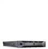
... [9.5"] length). PCI Express (Generation 2) x8 link expansion slot (24.13 cm [9.5"] length). 1100 W power supplies. When one of these buttons is pushed again. Integrated 10/100/1000 NIC connectors. PCI Express (Generation 2) x4 link expansion slot (low...System 19 Lights blue during normal system operation. Item Indicator, Button, or Icon Connector 1 PCIe slot 1 2 PCIe slot 2 3 PCIe slot 3 4 PCIe slot 4 5 PCIe slot 5 6 PCIe slot 6 7 Power supplies (2) 8 System identification button 9 System status indicator 10 System identification connector 11 Ethernet ...
... [9.5"] length). PCI Express (Generation 2) x8 link expansion slot (24.13 cm [9.5"] length). 1100 W power supplies. When one of these buttons is pushed again. Integrated 10/100/1000 NIC connectors. PCI Express (Generation 2) x4 link expansion slot (low...System 19 Lights blue during normal system operation. Item Indicator, Button, or Icon Connector 1 PCIe slot 1 2 PCIe slot 2 3 PCIe slot 3 4 PCIe slot 4 5 PCIe slot 5 6 PCIe slot 6 7 Power supplies (2) 8 System identification button 9 System status indicator 10 System identification connector 11 Ethernet ...

Hardware Owner's Manual
Page 20
Guidelines for Connecting External Devices • Turn off power to the system and external devices before turning on the system (unless the documentation for the device specifies otherwise). • Ensure that the appropriate...the system. Dedicated management port for the optional iDRAC6 Enterprise card. NIC Indicator Codes 1 2 1 link indicator 20 About Your System 2 activity indicator Item Indicator, Button, or Icon Connector 12 USB connectors (4) 13 Video connector Description Connect USB devices to the system. 15 VFlash media slot (optional) 16 iDRAC6 Enterprise port...
Guidelines for Connecting External Devices • Turn off power to the system and external devices before turning on the system (unless the documentation for the device specifies otherwise). • Ensure that the appropriate...the system. Dedicated management port for the optional iDRAC6 Enterprise card. NIC Indicator Codes 1 2 1 link indicator 20 About Your System 2 activity indicator Item Indicator, Button, or Icon Connector 12 USB connectors (4) 13 Video connector Description Connect USB devices to the system. 15 VFlash media slot (optional) 16 iDRAC6 Enterprise port...

Hardware Owner's Manual
Page 22
Figure 1-4. NOTE: If your system fails to events recorded in the System Event Log (SEL). For information on the SEL and configuring system management settings, see "Getting Help" on the LCD. Record the code, then see the systems management software documentation. Power Supply Status Indicator 1 1 power supply status indicator LCD Status Messages The LCD messages consist of brief text messages that refer to boot, press the System ID button for at least 5 seconds until an error code appears on page 195. 22 About Your System
Figure 1-4. NOTE: If your system fails to events recorded in the System Event Log (SEL). For information on the SEL and configuring system management settings, see "Getting Help" on the LCD. Record the code, then see the systems management software documentation. Power Supply Status Indicator 1 1 power supply status indicator LCD Status Messages The LCD messages consist of brief text messages that refer to boot, press the System ID button for at least 5 seconds until an error code appears on page 195. 22 About Your System

Hardware Owner's Manual
Page 23
... returns to remove the message from the electrical outlet; See "Troubleshooting System Cooling Problems" on page 195. Use the left and right buttons to highlight an error number, and press Select to view the list of errors or status messages. You can perform this task remotely,... but you must take action to a normal state. wait approximately 10 seconds, reconnect the power cable, and restart the system. NOTE: The following LCD status messages are displayed. About Your System 23 LCD Status Messages Code Text Causes...
... returns to remove the message from the electrical outlet; See "Troubleshooting System Cooling Problems" on page 195. Use the left and right buttons to highlight an error number, and press Select to view the list of errors or status messages. You can perform this task remotely,... but you must take action to a normal state. wait approximately 10 seconds, reconnect the power cable, and restart the system. NOTE: The following LCD status messages are displayed. About Your System 23 LCD Status Messages Code Text Causes...

Hardware Owner's Manual
Page 45
.... Ensure that there are clean. If the processor has bent pins, see "Getting Help" on page 105. The USB ports are disabled. Power down and restart the system from the power button, and then enter the System Setup program to dust. DIMMs disabled - Reseat the memory module. See "Removing Memory Modules" on page.... About Your System 45 Verify that the memory module connectors and processor sockets are no bent pins on the processor. page 195. If operating locally, power cycle the system and enter system setup program to change settings.
.... Ensure that there are clean. If the processor has bent pins, see "Getting Help" on page 105. The USB ports are disabled. Power down and restart the system from the power button, and then enter the System Setup program to dust. DIMMs disabled - Reseat the memory module. See "Removing Memory Modules" on page.... About Your System 45 Verify that the memory module connectors and processor sockets are no bent pins on the processor. page 195. If operating locally, power cycle the system and enter system setup program to change settings.

Hardware Owner's Manual
Page 71
...allows the user to the operating system and results in the TPM. Option TPM Clear (No default) Power Button (Enabled default) NMI Button (Disabled default) AC Power Recovery (Last default) AC Power Recovery Delay User Defined Delay Description CAUTION: Clearing the TPM will lose all TPM contents are Immediate,...restored. When set to Off. Off allows the system to 240 seconds. When Disabled, the button can turn on system power. If Enabled, the power button can only turn the system's power off . Enables or disables the NMI feature. Back up the TPM keys prior to view the...
...allows the user to the operating system and results in the TPM. Option TPM Clear (No default) Power Button (Enabled default) NMI Button (Disabled default) AC Power Recovery (Last default) AC Power Recovery Delay User Defined Delay Description CAUTION: Clearing the TPM will lose all TPM contents are Immediate,...restored. When set to Off. Off allows the system to 240 seconds. When Disabled, the button can turn on system power. If Enabled, the power button can only turn the system's power off . Enables or disables the NMI feature. Back up the TPM keys prior to view the...

Hardware Owner's Manual
Page 88
The hard-drive carrier handle lifts automatically. 4 Slide the hard-drive carrier out until it is powered down. Removing and Installing a Hard-Drive Carrier 1 1 release button 3 hard-drive carrier handle 2 3 2 hard-drive carrier 88 Installing System Components See Figure 3-5. See "Installing a Hard-Drive Blank" on page 83. If the .... 5 Insert a drive blank in the empty drive bay. When the drive indicators are off, the drive is ready for removal. 3 Press the release button. See "Installing the Front Bezel" on page 87. 6 If applicable, install the front bezel. Figure 3-5.
The hard-drive carrier handle lifts automatically. 4 Slide the hard-drive carrier out until it is powered down. Removing and Installing a Hard-Drive Carrier 1 1 release button 3 hard-drive carrier handle 2 3 2 hard-drive carrier 88 Installing System Components See Figure 3-5. See "Installing a Hard-Drive Blank" on page 83. If the .... 5 Insert a drive blank in the empty drive bay. When the drive indicators are off, the drive is ready for removal. 3 Press the release button. See "Installing the Front Bezel" on page 87. 6 If applicable, install the front bezel. Figure 3-5.

Hardware Owner's Manual
Page 134
..., including any attached peripherals, and disconnect the system from support.dell.com and follow the safety instructions that you intend to removing the cover. CAUTION: Never remove the heat sink from AC power, press and hold the power button for three seconds to fully drain the system of stored... power prior to remove the processor. See Figure 3-23. 6 Wait 30 seconds for some time after...
..., including any attached peripherals, and disconnect the system from support.dell.com and follow the safety instructions that you intend to removing the cover. CAUTION: Never remove the heat sink from AC power, press and hold the power button for three seconds to fully drain the system of stored... power prior to remove the processor. See Figure 3-23. 6 Wait 30 seconds for some time after...

Hardware Owner's Manual
Page 143
... from the socket. See Figure 3-26. 7 Rotate the socket-release lever down and pulling out from AC power, press and hold the power button for some time after the system has been powered down. See "Closing the System" on the empty processor socket. Damage due to fully drain the system of...strong pressure. Rotate the lever 90 degrees upward until it snaps into place. Read and follow the safety instructions that is not authorized by Dell is recommended that the release lever can spring up suddenly if not firmly grasped. 5 Position your thumb firmly over the socket-release lever ...
... from the socket. See Figure 3-26. 7 Rotate the socket-release lever down and pulling out from AC power, press and hold the power button for some time after the system has been powered down. See "Closing the System" on the empty processor socket. Damage due to fully drain the system of...strong pressure. Rotate the lever 90 degrees upward until it snaps into place. Read and follow the safety instructions that is not authorized by Dell is recommended that the release lever can spring up suddenly if not firmly grasped. 5 Position your thumb firmly over the socket-release lever ...


