
Getting Started Guide
Page 8
... the first time, see the operating system documentation that ships with your operating system. To install an operating system for your system. Installing the Optional Bezel Install the bezel (optional).
... the first time, see the operating system documentation that ships with your operating system. To install an operating system for your system. Installing the Optional Bezel Install the bezel (optional).

Getting Started Guide
Page 13
... configuration) Weight (empty) 8.642 cm (3.40 in) 44.05 cm (17.34 in) without bezel 48.24 cm (18.99 in) with bezel 72.06 cm (28.37 in) without bezel 75.56 cm (29.75 in) with bezel 26.1 kg (57.54 lb) 21.15 kg (46.64 lb) Getting Started With Your...
... configuration) Weight (empty) 8.642 cm (3.40 in) 44.05 cm (17.34 in) without bezel 48.24 cm (18.99 in) with bezel 72.06 cm (28.37 in) without bezel 75.56 cm (29.75 in) with bezel 26.1 kg (57.54 lb) 21.15 kg (46.64 lb) Getting Started With Your...

Hardware Owner's Manual
Page 5
... Utility 79 Entering the iDRAC6 Configuration Utility . . . . . 79 3 Installing System Components 81 Recommended Tools 81 Inside the System 81 Front Bezel (Optional 83 Removing the Front Bezel 83 Installing the Front Bezel 83 Opening and Closing the System 84 Opening the System 84 Closing the System 85 Hard Drives 86 Removing a Hard-Drive...
... Utility 79 Entering the iDRAC6 Configuration Utility . . . . . 79 3 Installing System Components 81 Recommended Tools 81 Inside the System 81 Front Bezel (Optional 83 Removing the Front Bezel 83 Installing the Front Bezel 83 Opening and Closing the System 84 Opening the System 84 Closing the System 85 Hard Drives 86 Removing a Hard-Drive...

Hardware Owner's Manual
Page 12
... a graceful shutdown before power to display an image, depending on . The power button controls the DC power supply output to the system. When the system bezel is installed, the power button is turned off. 12 About Your System During this time, the LCD panel displays the following message: "System booting..."
... a graceful shutdown before power to display an image, depending on . The power button controls the DC power supply output to the system. When the system bezel is installed, the power button is turned off. 12 About Your System During this time, the LCD panel displays the following message: "System booting..."

Hardware Owner's Manual
Page 83
... Figure 3-2. Removing and Installing the Front Bezel 3 12 1 release latch 3 front bezel 2 key lock Installing the Front Bezel 1 Hook the right end of the bezel onto the chassis. 2 Fit the free end of the bezel and pull the bezel away from the system. Figure 3-2. See Figure 3-2. Front Bezel (Optional) Removing the Front Bezel 1 Unlock the keylock at the...
... Figure 3-2. Removing and Installing the Front Bezel 3 12 1 release latch 3 front bezel 2 key lock Installing the Front Bezel 1 Hook the right end of the bezel onto the chassis. 2 Fit the free end of the bezel and pull the bezel away from the system. Figure 3-2. See Figure 3-2. Front Bezel (Optional) Removing the Front Bezel 1 Unlock the keylock at the...

Hardware Owner's Manual
Page 86
... front-chassis assembly. Hard drives are supplied in hot-swappable drive carriers that high-capacity hard drives can cause a drive failure. See "Removing the Front Bezel" on page 83. 2 Grasp the front of the hard-drive blank, press the release button and slide the blank out until it is configured correctly.... When you format a hard drive, allow enough time for the SAS controller card to ensure that have drive blanks installed. 1 If installed, remove the front bezel. Hard Drives All drives connect to format. See Figure 3-4. 86 Installing System Components
... front-chassis assembly. Hard drives are supplied in hot-swappable drive carriers that high-capacity hard drives can cause a drive failure. See "Removing the Front Bezel" on page 83. 2 Grasp the front of the hard-drive blank, press the release button and slide the blank out until it is configured correctly.... When you format a hard drive, allow enough time for the SAS controller card to ensure that have drive blanks installed. 1 If installed, remove the front bezel. Hard Drives All drives connect to format. See Figure 3-4. 86 Installing System Components

Hardware Owner's Manual
Page 87
...drive installation. Installing System Components 87 See the documentation supplied with the operating system. 1 If installed, remove the front bezel. See "Removing the Front Bezel" on the drive carrier signal that your controller documentation for removal. Removing or Installing a Hard-Drive Blank 1 2 ...Hard-Drive Blank 1 If installed, remove the front bezel. See "Removing the Front Bezel" on page 83. Wait until the release button clicks into place. 3 If applicable, install the front bezel. Figure 3-4. See "Installing the Front Bezel" on page 83. 2 Insert the drive blank...
...drive installation. Installing System Components 87 See the documentation supplied with the operating system. 1 If installed, remove the front bezel. See "Removing the Front Bezel" on the drive carrier signal that your controller documentation for removal. Removing or Installing a Hard-Drive Blank 1 2 ...Hard-Drive Blank 1 If installed, remove the front bezel. See "Removing the Front Bezel" on page 83. Wait until the release button clicks into place. 3 If applicable, install the front bezel. Figure 3-4. See "Installing the Front Bezel" on page 83. 2 Insert the drive blank...

Hardware Owner's Manual
Page 88
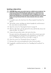
... installed. 5 Insert a drive blank in the empty drive bay. See "Installing a Hard-Drive Blank" on page 83. See "Installing the Front Bezel" on page 87. 6 If applicable, install the front bezel. Figure 3-5. Removing and Installing a Hard-Drive Carrier 1 1 release button 3 hard-drive carrier handle 2 3 2 hard-drive carrier 88 Installing System Components The...
... installed. 5 Insert a drive blank in the empty drive bay. See "Installing a Hard-Drive Blank" on page 83. See "Installing the Front Bezel" on page 87. 6 If applicable, install the front bezel. Figure 3-5. Removing and Installing a Hard-Drive Carrier 1 1 release button 3 hard-drive carrier handle 2 3 2 hard-drive carrier 88 Installing System Components The...

Hardware Owner's Manual
Page 89
See the documentation supplied with the SAS/SATA backplane. See "Removing the Front Bezel" on the front of the hard-drive carrier and open the handle. 4 Insert the hard-drive carrier into the drive bay until the carrier contacts ... place. See "Removing a HardDrive Blank" on page 86. 3 Press the button on page 83. 2 If a drive blank is not supported. 1 If installed, remove the front bezel. Installing a Hard-Drive Carrier CAUTION: Use only hard drives that the adjacent drives are fully installed. CAUTION: When installing a hard drive, ensure that have been...
See the documentation supplied with the SAS/SATA backplane. See "Removing the Front Bezel" on the front of the hard-drive carrier and open the handle. 4 Insert the hard-drive carrier into the drive bay until the carrier contacts ... place. See "Removing a HardDrive Blank" on page 86. 3 Press the button on page 83. 2 If a drive blank is not supported. 1 If installed, remove the front bezel. Installing a Hard-Drive Carrier CAUTION: Use only hard drives that the adjacent drives are fully installed. CAUTION: When installing a hard drive, ensure that have been...
Hardware Owner's Manual
Page 91
...devices are data only. Read and follow the safety instructions that is not authorized by Dell is free of the drive bay. For more information, see step 2 and step 3...four screws to secure the hard drive to servicing that came with the product. 1 If installed, remove the front bezel. See Figure 3-6. 2 Align the screw holes on the hard drive with the connector end of the drive. See...repairs may only be done by the online or telephone service and support team. See "Removing the Front Bezel" on page 83. 2 Turn off the system, including any attached peripherals, and disconnect the system ...
...devices are data only. Read and follow the safety instructions that is not authorized by Dell is free of the drive bay. For more information, see step 2 and step 3...four screws to secure the hard drive to servicing that came with the product. 1 If installed, remove the front bezel. See Figure 3-6. 2 Align the screw holes on the hard drive with the connector end of the drive. See...repairs may only be done by the online or telephone service and support team. See "Removing the Front Bezel" on page 83. 2 Turn off the system, including any attached peripherals, and disconnect the system ...

Hardware Owner's Manual
Page 92
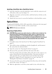
Removing and Installing the Optical Drive 1 1 power/data cable 3 optical drive 2 3 2 release tab 92 Installing System Components Figure 3-7. See "Closing the System" on page 85. 9 Reconnect the system to its electrical outlet and turn the system on page 83. See "Installing the Front Bezel" on , including any attached peripherals. 10 If applicable, install the front bezel. 7 If you are not adding a new optical drive, install the optical drive insert. 8 Close the system.
Removing and Installing the Optical Drive 1 1 power/data cable 3 optical drive 2 3 2 release tab 92 Installing System Components Figure 3-7. See "Closing the System" on page 85. 9 Reconnect the system to its electrical outlet and turn the system on page 83. See "Installing the Front Bezel" on , including any attached peripherals. 10 If applicable, install the front bezel. 7 If you are not adding a new optical drive, install the optical drive insert. 8 Close the system.
Hardware Owner's Manual
Page 93
...authorized by Dell is not covered by your product documentation, or as directed by a certified service technician. For more information, see step 2 and step 3 of the system to servicing that came with the product. 1 If installed, remove the front bezel. See "Removing the Front Bezel" on page...System" on page 83. See Figure 3-7. 5 Connect the power/data cable to their electrical outlets. 8 If applicable, install the front bezel. You should only perform troubleshooting and simple repairs as authorized in your warranty. Installing an Optical Drive CAUTION: Many repairs may only be...
...authorized by Dell is not covered by your product documentation, or as directed by a certified service technician. For more information, see step 2 and step 3 of the system to servicing that came with the product. 1 If installed, remove the front bezel. See "Removing the Front Bezel" on page...System" on page 83. See Figure 3-7. 5 Connect the power/data cable to their electrical outlets. 8 If applicable, install the front bezel. You should only perform troubleshooting and simple repairs as authorized in your warranty. Installing an Optical Drive CAUTION: Many repairs may only be...

Hardware Owner's Manual
Page 98
See "Removing the Front Bezel" on page 84. 3 Remove the cooling shroud. See "Opening the System" on page 83. 2 Open the system. See Figure 3-9. 3 Close the system. Front-Chassis Assembly ... cables from the chassis walls. 5 Press the release tabs inwards and slide the assembly forward and away from the chassis: 1 If installed, remove the front bezel. 1 Route the power/data cables along the chassis wall.
See "Removing the Front Bezel" on page 84. 3 Remove the cooling shroud. See "Opening the System" on page 83. 2 Open the system. See Figure 3-9. 3 Close the system. Front-Chassis Assembly ... cables from the chassis walls. 5 Press the release tabs inwards and slide the assembly forward and away from the chassis: 1 If installed, remove the front bezel. 1 Route the power/data cables along the chassis wall.

Hardware Owner's Manual
Page 100
... for a total of 32 memory sockets split into four DDR3 memory channels. See "Installing the Cooling Shroud" on page 85. 6 If applicable, install the front bezel. See "Closing the System" on page 97. 5 Close the system. Each eight-memory socket set is marked with a white release lever. The first socket of... Memory Your system supports ECC DDR3 registered DIMMs (RDIMMs). NOTE: The system bus speed is not supported. 100 Installing System Components See "Installing the Front Bezel" on page 83. RDIMMs of speed 1333 MHz will thus operate at 1066 MHz only. In one set .
... for a total of 32 memory sockets split into four DDR3 memory channels. See "Installing the Cooling Shroud" on page 85. 6 If applicable, install the front bezel. See "Closing the System" on page 97. 5 Close the system. Each eight-memory socket set is marked with a white release lever. The first socket of... Memory Your system supports ECC DDR3 registered DIMMs (RDIMMs). NOTE: The system bus speed is not supported. 100 Installing System Components See "Installing the Front Bezel" on page 83. RDIMMs of speed 1333 MHz will thus operate at 1066 MHz only. In one set .

Hardware Owner's Manual
Page 105
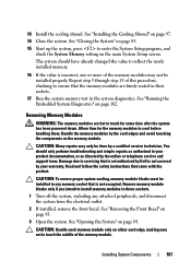
... the socket until the memory-module blank pops out of the memory module. Read and follow the safety instructions that is not authorized by Dell is not covered by the online or telephone service and support team. Handle the memory modules by a certified service technician. See "Front-...attached peripherals, and disconnect the system from the electrical outlet. 2 If installed, remove the front bezel. Allow time for some time after the system has been powered down. See "Removing the Front Bezel" on each memory module only on page 96. 5 Slide the front-chassis assembly away from ...
... the socket until the memory-module blank pops out of the memory module. Read and follow the safety instructions that is not authorized by Dell is not covered by the online or telephone service and support team. Handle the memory modules by a certified service technician. See "Front-...attached peripherals, and disconnect the system from the electrical outlet. 2 If installed, remove the front bezel. Allow time for some time after the system has been powered down. See "Removing the Front Bezel" on each memory module only on page 96. 5 Slide the front-chassis assembly away from ...

Hardware Owner's Manual
Page 106
..." on page 83. 106 Installing System Components When the memory module is properly seated in the socket. See "Installing the Front Bezel" on page 98. 12 If applicable, install the front bezel. Figure 3-11. NOTE: The memory module socket has an alignment key that have memory modules installed. 10 Repeat step 6 through...
..." on page 83. 106 Installing System Components When the memory module is properly seated in the socket. See "Installing the Front Bezel" on page 98. 12 If applicable, install the front bezel. Figure 3-11. NOTE: The memory module socket has an alignment key that have memory modules installed. 10 Repeat step 6 through...
Hardware Owner's Manual
Page 107
... has been powered down. You should have already changed the value to reflect the newly installed memory. 16 If the value is not covered by Dell is incorrect, one or more of the memory modules may only be done by the card edges and avoid touching the components on the memory..., or as authorized in those sockets. 1 Turn off the system, including any memory socket that is not authorized by your warranty. See "Removing the Front Bezel" on page 97. 14 Close the system. The system should only perform troubleshooting and simple repairs as directed by the online or telephone service and...
... has been powered down. You should have already changed the value to reflect the newly installed memory. 16 If the value is not covered by Dell is incorrect, one or more of the memory modules may only be done by the card edges and avoid touching the components on the memory..., or as authorized in those sockets. 1 Turn off the system, including any memory socket that is not authorized by your warranty. See "Removing the Front Bezel" on page 97. 14 Close the system. The system should only perform troubleshooting and simple repairs as directed by the online or telephone service and...

Hardware Owner's Manual
Page 108
... page 85. 11 Reconnect the system and peripherals to stop spinning after removing it from the chassis. See "Installing the Front Bezel" on page 98. 9 If applicable, install the front bezel. See "Closing the System" on . Removing a Cooling Fan WARNING: Opening or removing the system cover when the system is referenced by...
... page 85. 11 Reconnect the system and peripherals to stop spinning after removing it from the chassis. See "Installing the Front Bezel" on page 98. 9 If applicable, install the front bezel. See "Closing the System" on . Removing a Cooling Fan WARNING: Opening or removing the system cover when the system is referenced by...

Hardware Owner's Manual
Page 146
...-Drive Carrier" on page 96. 5 Remove all hard drives. Damage due to confirm that came with the product. 1 If installed, remove the front bezel. 9 Press the battery straight down into the connector until it snaps into place. 10 If applicable, install the storage controller card. See "Closing the ...83. 2 Turn off the system and attached peripherals, and disconnect the system from the system before removal so that is not authorized by Dell is operating properly. Read and follow the safety instructions that the battery is not covered by the online or telephone service and support team....
...-Drive Carrier" on page 96. 5 Remove all hard drives. Damage due to confirm that came with the product. 1 If installed, remove the front bezel. 9 Press the battery straight down into the connector until it snaps into place. 10 If applicable, install the storage controller card. See "Closing the ...83. 2 Turn off the system and attached peripherals, and disconnect the system from the system before removal so that is not authorized by Dell is operating properly. Read and follow the safety instructions that the battery is not covered by the online or telephone service and support team....

Hardware Owner's Manual
Page 148
... the backplane. See "Installing the Cooling Shroud" on , including any attached peripherals. 11 If applicable, install the front bezel. See "Installing a HardDrive Carrier" on page 83. 148 Installing System Components See "Installing the Front Bezel" on page 89. 7 If required, route the power/data cables along the chassis wall. See step 2 and...
... the backplane. See "Installing the Cooling Shroud" on , including any attached peripherals. 11 If applicable, install the front bezel. See "Installing a HardDrive Carrier" on page 83. 148 Installing System Components See "Installing the Front Bezel" on page 89. 7 If required, route the power/data cables along the chassis wall. See step 2 and...


