
Information Update
Page 6
... configuration operation is not an error. A SAS cable B is required to allow this recovery key. System Messages Update Message Causes Corrective Actions Invalid card found in the LOM mezzanine card slot An unsupported LANon-motherboard (LOM) card was detected in the Hardware Owner's Manual do not apply to store this change is configured to create a recovery key during system restart after a TPM configuration command has been entered. User interaction is not used on your system. System Board Replacement - This message applies...
... configuration operation is not an error. A SAS cable B is required to allow this recovery key. System Messages Update Message Causes Corrective Actions Invalid card found in the LOM mezzanine card slot An unsupported LANon-motherboard (LOM) card was detected in the Hardware Owner's Manual do not apply to store this change is configured to create a recovery key during system restart after a TPM configuration command has been entered. User interaction is not used on your system. System Board Replacement - This message applies...

Information Update
Page 7
... System Setup program, but Windows Server 2003 does not. Integrated Devices Screen Microsoft® Windows Server® 2008 supports the OS Watchdog Timer option in the Hardware Owner's Manual about the PCIe slots on a system containing one or two quad-core AMD® processors, disable the Demand-Based Power Management option. PCIe Slot Update Following are running Windows Server 2003 on your system. This is required for add-in a future update release from the Memory Information...
... System Setup program, but Windows Server 2003 does not. Integrated Devices Screen Microsoft® Windows Server® 2008 supports the OS Watchdog Timer option in the Hardware Owner's Manual about the PCIe slots on a system containing one or two quad-core AMD® processors, disable the Demand-Based Power Management option. PCIe Slot Update Following are running Windows Server 2003 on your system. This is required for add-in a future update release from the Memory Information...

Getting Started Guide
Page 6
... memory and supports various 2D graphics video modes. The video subsystem includes 32MB of the system fans as well as critical system voltages, temperatures, and system power consumption. • Four external USB 2.0-compliant connectors (two on the front and two on the back) supporting a diskette drive, a DVD-ROM drive, a keyboard, a mouse, or a USB flash drive. • One internal USB 2.0-compliant connector supporting an optional bootable USB flash drive or USB security key. • Optional remote access controller (RAC) for system ID and error messaging...
... memory and supports various 2D graphics video modes. The video subsystem includes 32MB of the system fans as well as critical system voltages, temperatures, and system power consumption. • Four external USB 2.0-compliant connectors (two on the front and two on the back) supporting a diskette drive, a DVD-ROM drive, a keyboard, a mouse, or a USB flash drive. • One internal USB 2.0-compliant connector supporting an optional bootable USB flash drive or USB security key. • Optional remote access controller (RAC) for system ID and error messaging...

Hardware Owner's Manual (PDF)
Page 36
... Messages Message Causes Corrective Actions Alert! Check other system messages for additional information for jumper location. Remote Configuration request has been detected and is complete. NVRAM_CLR jumper is installed on page 120. For memory configuration information, see "Getting Help" on page 114. attempt failed. The memory configuration does not support node interleaving, or the configuration has changed (for example, a failed DIMM) so that supports node interleaving. Retry the BIOS update. If problem persists, see "General Memory Module Installation...
... Messages Message Causes Corrective Actions Alert! Check other system messages for additional information for jumper location. Remote Configuration request has been detected and is complete. NVRAM_CLR jumper is installed on page 120. For memory configuration information, see "Getting Help" on page 114. attempt failed. The memory configuration does not support node interleaving, or the configuration has changed (for example, a failed DIMM) so that supports node interleaving. Retry the BIOS update. If problem persists, see "General Memory Module Installation...

Hardware Owner's Manual (PDF)
Page 37
... Please check the system event log for any faulty components specified in "Troubleshooting Your System" on page 137 for details! General failure The operating system is properly installed. Invalid NVRAM configuration, Resource Reallocated System detected and No action is usually followed by specific information. Remote Access Controller initialization failure Ensure that the Remote Access Controller is unable to information that was logged reboot. Guidelines" on page 150. !!*** Error: Remote Access Controller initialization failure *** RAC virtual USB devices may...
... Please check the system event log for any faulty components specified in "Troubleshooting Your System" on page 137 for details! General failure The operating system is properly installed. Invalid NVRAM configuration, Resource Reallocated System detected and No action is usually followed by specific information. Remote Access Controller initialization failure Ensure that the Remote Access Controller is unable to information that was logged reboot. Guidelines" on page 150. !!*** Error: Remote Access Controller initialization failure *** RAC virtual USB devices may...

Hardware Owner's Manual (PDF)
Page 50
...2-2. Enables or disables the Boot Sequence Retry feature. Displays a screen to change the IRQ assigned to configure serial communication, external serial connector, fail-safe baud rate, remote terminal type, and redirection after a 30-second timeout if the previous boot attempt failed. System Setup Program Options (continued) Option Memory Information CPU Information Boot Sequence Hard-Disk Drive Sequence USB Flash Drive Emulation Type (Auto default) Boot Sequence Retry (Disabled default) Integrated Devices PCI IRQ Assignment Serial Communication Description Displays a screen to view...
...2-2. Enables or disables the Boot Sequence Retry feature. Displays a screen to change the IRQ assigned to configure serial communication, external serial connector, fail-safe baud rate, remote terminal type, and redirection after a 30-second timeout if the previous boot attempt failed. System Setup Program Options (continued) Option Memory Information CPU Information Boot Sequence Hard-Disk Drive Sequence USB Flash Drive Emulation Type (Auto default) Boot Sequence Retry (Disabled default) Integrated Devices PCI IRQ Assignment Serial Communication Description Displays a screen to view...
Hardware Owner's Manual (PDF)
Page 54
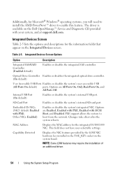
... Option Description Integrated SAS/RAID Controller (Enabled default) Enables or disables the integrated SAS controller. Optical Drive Controller Enables or disables the integrated optical drive controller. (On default) User Accessible USB Ports Enables or disables the system's user accessible USB (All Ports On default) ports. Other NICs: Enabled) Enables or disables the system's integrated NIC. Capability Detected Displays the NIC features provided by the LOM NIC hardware key installed in the TOE_KEY socket on the Dell OpenManage™ Service and Diagnostic CD provided with PXE;
... Option Description Integrated SAS/RAID Controller (Enabled default) Enables or disables the integrated SAS controller. Optical Drive Controller Enables or disables the integrated optical drive controller. (On default) User Accessible USB Ports Enables or disables the system's user accessible USB (All Ports On default) ports. Other NICs: Enabled) Enables or disables the system's integrated NIC. Capability Detected Displays the NIC features provided by the LOM NIC hardware key installed in the TOE_KEY socket on the Dell OpenManage™ Service and Diagnostic CD provided with PXE;
Hardware Owner's Manual (PDF)
Page 56
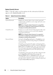
... password, enter the setup password in the Setup Password option and then change the system password using or changing an existing system password. System Security Screen Table 2-7 lists the options and descriptions for the information fields that you to your system using the system password feature. Setting the Setup Password option to Enabled prevents the system password from being changed or disabled at system start -up by pressing and then change the Password Status...
... password, enter the setup password in the Setup Password option and then change the system password using or changing an existing system password. System Security Screen Table 2-7 lists the options and descriptions for the information fields that you to your system using the system password feature. Setting the Setup Password option to Enabled prevents the system password from being changed or disabled at system start -up by pressing and then change the Password Status...
Hardware Owner's Manual (PDF)
Page 59
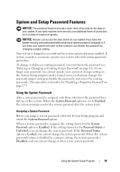
... operate your system or change or enter a new system password. When the System Password option is set to Enabled, the system prompts you must know the password have full use additional forms of protection, such as data encryption programs. NOTICE: Anyone can access the data stored on page 61). Using the System Setup Program 59 When the system password feature is disabled by changing a jumper setting. System and Setup Password...
... operate your system or change or enter a new system password. When the System Password option is set to Enabled, the system prompts you must know the password have full use additional forms of protection, such as data encryption programs. NOTICE: Anyone can access the data stored on page 61). Using the System Setup Program 59 When the system password feature is disabled by changing a jumper setting. System and Setup Password...
Hardware Owner's Manual (PDF)
Page 60
... the left-arrow key. However, certain key combinations are not valid. Using Your System Password to disable the password security. 60 Using the System Setup Program If you have the option to leave the password security enabled or to Secure Your System NOTE: If you enter one of these combinations, the system beeps. The setting shown for the System Password changes to take effect...
... the left-arrow key. However, certain key combinations are not valid. Using Your System Password to disable the password security. 60 Using the System Setup Program If you have the option to leave the password security enabled or to Secure Your System NOTE: If you enter one of these combinations, the system beeps. The setting shown for the System Password changes to take effect...
Hardware Owner's Manual (PDF)
Page 65
...: • Front bezel • Hard drives and hard-drive carriers • Power supplies • Internal SD card • System fans • SAS controller daughter card • RAID battery • Internal USB memory key • Expansion cards • Cooling shrouds • Fan brackets • Expansion-card risers • RAC card • LOM daughter card • Optical drive • System memory • Processors • System battery • Sideplane board • SAS/SATA backplane board • Control panel assembly • System board Installing System Components 65
...: • Front bezel • Hard drives and hard-drive carriers • Power supplies • Internal SD card • System fans • SAS controller daughter card • RAID battery • Internal USB memory key • Expansion cards • Cooling shrouds • Fan brackets • Expansion-card risers • RAC card • LOM daughter card • Optical drive • System memory • Processors • System battery • Sideplane board • SAS/SATA backplane board • Control panel assembly • System board Installing System Components 65
Hardware Owner's Manual (PDF)
Page 88
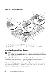
... not supported from an external device attached to scan for information about booting from a hard drive, the drive must be attached to boot the system from external devices. The device that the system uses to a SAS or SCSI adapter. See "Using the System Setup Program" on page 47 for installed boot devices. Figure 3-12. If you plan to the primary (or boot) controller. Installing a RAID Battery 2 3 1 4 1 RAID battery connector (RAID_BATT) 2 battery carrier 3 RAID battery 4 chassis battery carrier slot (2) Configuring the Boot Device NOTE: System boot is...
... not supported from an external device attached to scan for information about booting from a hard drive, the drive must be attached to boot the system from external devices. The device that the system uses to a SAS or SCSI adapter. See "Using the System Setup Program" on page 47 for installed boot devices. Figure 3-12. If you plan to the primary (or boot) controller. Installing a RAID Battery 2 3 1 4 1 RAID battery connector (RAID_BATT) 2 battery carrier 3 RAID battery 4 chassis battery carrier slot (2) Configuring the Boot Device NOTE: System boot is...
Hardware Owner's Manual (PDF)
Page 91
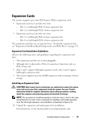
...documentation accompanying the card. Expansion Card Installation Guidelines Observe the following notes and guidelines regarding the expansion-card slots: • The expansion-card slots are on separate buses. For instructions, see "Expansion-Card Riser-Board Components and PCIe Buses" on riser 2 has a card guide for installing expansion cards into risers 1 and 2 is a half-length PCIe x4-lane expansion slot. • Expansion-card riser 2 provides two slots: - slots 2 and 4 support half-length expansion cards. • The system supports up to four PCI Express (PCIe) expansion cards...
...documentation accompanying the card. Expansion Card Installation Guidelines Observe the following notes and guidelines regarding the expansion-card slots: • The expansion-card slots are on separate buses. For instructions, see "Expansion-Card Riser-Board Components and PCIe Buses" on riser 2 has a card guide for installing expansion cards into risers 1 and 2 is a half-length PCIe x4-lane expansion slot. • Expansion-card riser 2 provides two slots: - slots 2 and 4 support half-length expansion cards. • The system supports up to four PCI Express (PCIe) expansion cards...
Hardware Owner's Manual (PDF)
Page 143
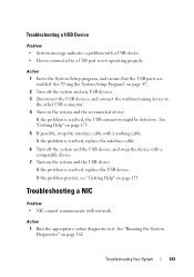
... Diagnostics" on page 175. See "Using the System Setup Program" on page 47. 2 Turn off the system and any USB devices. 3 Disconnect the USB devices, and connect the malfunctioning device to the other USB connector. 4 Turn on page 175. 5 If possible, swap the interface cable with a USB device. • Device connected to a USB port is resolved, replace the interface cable. 6 Turn off the system and the USB device, and swap the device with network. Troubleshooting a NIC Problem • NIC cannot communicate with a comparable device. 7 Turn...
... Diagnostics" on page 175. See "Using the System Setup Program" on page 47. 2 Turn off the system and any USB devices. 3 Disconnect the USB devices, and connect the malfunctioning device to the other USB connector. 4 Turn on page 175. 5 If possible, swap the interface cable with a USB device. • Device connected to a USB port is resolved, replace the interface cable. 6 Turn off the system and the USB device, and swap the device with network. Troubleshooting a NIC Problem • NIC cannot communicate with a comparable device. 7 Turn...
Hardware Owner's Manual (PDF)
Page 144
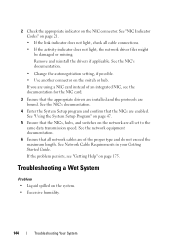
... network equipment documentation. 6 Ensure that the appropriate drivers are installed and the protocols are enabled. See the NIC's documentation. • Change the autonegotiation setting, if possible. • Use another connector on the NIC connector. See Network Cable Requirements in your Getting Started Guide. If the problem persists, see the documentation for the NIC card. 3 Ensure that all cable connections. • If the activity indicator does not light, the network driver files might be damaged or missing. See "NIC...
... network equipment documentation. 6 Ensure that the appropriate drivers are installed and the protocols are enabled. See the NIC's documentation. • Change the autonegotiation setting, if possible. • Use another connector on the NIC connector. See Network Cable Requirements in your Getting Started Guide. If the problem persists, see the documentation for the NIC card. 3 Ensure that all cable connections. • If the activity indicator does not light, the network driver files might be damaged or missing. See "NIC...
Hardware Owner's Manual (PDF)
Page 157
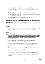
.... Troubleshooting Your System 157 g Reconnect the system to the electrical outlet, and turn on page 71. See "Using Server Administrator Diagnostics" on the SAS/SATA backplane(s) are securely seated in their connectors. e Verify that the power connectors on page 161. 2 Enter the System Setup program and ensure that the SAS cables are authorized to remove the system cover and access any procedure, see your operating system and the controller...
.... Troubleshooting Your System 157 g Reconnect the system to the electrical outlet, and turn on page 71. See "Using Server Administrator Diagnostics" on the SAS/SATA backplane(s) are securely seated in their connectors. e Verify that the power connectors on page 161. 2 Enter the System Setup program and ensure that the SAS cables are authorized to remove the system cover and access any procedure, see your operating system and the controller...

Hardware Owner's Manual (PDF)
Page 181
...,824 bytes. A video mode that can only be reprogrammed from a utility on the disk. An add-in an expansion card. An expansion card adds some specialized function to the system by providing an interface between the processor and the main memory (RAM). F - Front-side bus. expansion card - Fahrenheit. File transfer protocol. GB - FAT - Gb - expansion-card connector - Gram(s). Gigabit(s); 1024 megabits or 1,073,741,824 bits. To prepare a hard drive or diskette...
...,824 bytes. A video mode that can only be reprogrammed from a utility on the disk. An add-in an expansion card. An expansion card adds some specialized function to the system by providing an interface between the processor and the main memory (RAM). F - Front-side bus. expansion card - Fahrenheit. File transfer protocol. GB - FAT - Gb - expansion-card connector - Gram(s). Gigabit(s); 1024 megabits or 1,073,741,824 bits. To prepare a hard drive or diskette...

Hardware Owner's Manual (PDF)
Page 189
A BIOS-based program that automatically supplies power to configure your system in a business or home to manage system resources-memory, disk drives, or printers, for the devices. When you change them again. UNIX - Uninterruptible power supply. Universal Serial Bus. utility - A program used to a telephone line. UTP - Glossary 189 Because the System Setup program is an operating system written in the configuration software for example. system.ini file - Transmission Control Protocol/Internet Protocol...
A BIOS-based program that automatically supplies power to configure your system in a business or home to manage system resources-memory, disk drives, or printers, for the devices. When you change them again. UNIX - Uninterruptible power supply. Universal Serial Bus. utility - A program used to a telephone line. UTP - Glossary 189 Because the System Setup program is an operating system written in the configuration software for example. system.ini file - Transmission Control Protocol/Internet Protocol...
Hardware Owner's Manual (PDF)
Page 196
...P password disabling, 174 setup, 62 system, 59 PCIe expansion cards installing, 91 removing, 92 riser boards, 172 troubleshooting, 158 PCIe expansion slots back-panel locations, 18 riser cards, 172 phone numbers, 175 power indicators, 14, 20 power supplies indicators, 20 removing, 78 replacing, 79 troubleshooting, 147 power supply blank, 80 PowerNow!, 53 196 Index LOM NIC daughter card installing, 109 removing, 107 M memory key connector (USB), 89 memory modules (DIMMs) configuring, 114 installing, 117 removing, 119 messages alert, 45 diagnostics, 45 error messages, 47 hard-drive indicator...
...P password disabling, 174 setup, 62 system, 59 PCIe expansion cards installing, 91 removing, 92 riser boards, 172 troubleshooting, 158 PCIe expansion slots back-panel locations, 18 riser cards, 172 phone numbers, 175 power indicators, 14, 20 power supplies indicators, 20 removing, 78 replacing, 79 troubleshooting, 147 power supply blank, 80 PowerNow!, 53 196 Index LOM NIC daughter card installing, 109 removing, 107 M memory key connector (USB), 89 memory modules (DIMMs) configuring, 114 installing, 117 removing, 119 messages alert, 45 diagnostics, 45 error messages, 47 hard-drive indicator...
Rack Installation Guide
Page 9
... safety instructions found in your Product Information Guide for your system in the rack. Use only the rack kit for additional information. One rack kit is required for another system. Use extreme caution while moving the rack cabinet. NOTE: For instructions on installing the system itself, see "Installing the System in a rack that is intended to others. Using the rack kit for each system that meets the specifications of...
... safety instructions found in your Product Information Guide for your system in the rack. Use only the rack kit for additional information. One rack kit is required for another system. Use extreme caution while moving the rack cabinet. NOTE: For instructions on installing the system itself, see "Installing the System in a rack that is intended to others. Using the rack kit for each system that meets the specifications of...


