
EMC Systems Management Overview Guide Version 20.0
Page 10
...applied throughout. It helps reduce costs and consolidates multiple tools for the Redfish standard and enhances it with Dell EMC extensions to tailor an effective, affordable solution for PowerEdge servers, data center and IT administrators can rapidly deploy their fingertips. just plug in power and network... management. Because iDRAC is embedded in place across the Dell EMC PowerEdge portfolio, the same IT administration techniques and tools can enable and disable features on iSM by the iDRAC interfaces to control the CPU and memory consumed on (SSO) to access iDRAC GUI from Host...
...applied throughout. It helps reduce costs and consolidates multiple tools for the Redfish standard and enhances it with Dell EMC extensions to tailor an effective, affordable solution for PowerEdge servers, data center and IT administrators can rapidly deploy their fingertips. just plug in power and network... management. Because iDRAC is embedded in place across the Dell EMC PowerEdge portfolio, the same IT administration techniques and tools can enable and disable features on iSM by the iDRAC interfaces to control the CPU and memory consumed on (SSO) to access iDRAC GUI from Host...
EMC Systems Management Overview Guide Version 20.0
Page 15
... includes dashboard and reporting on the server environment. Systems Management Product Overview 15 Dell EMC Server PRO System Center Management Pack for Microsoft System Center Virtual Machine Manager Dell EMC server PRO Management Pack integrates PowerEdge server knowledge on temperature, memory, and power supplies with OpenManage Integration for Microsoft System Center Virtual Machine Manager...
... includes dashboard and reporting on the server environment. Systems Management Product Overview 15 Dell EMC Server PRO System Center Management Pack for Microsoft System Center Virtual Machine Manager Dell EMC server PRO Management Pack integrates PowerEdge server knowledge on temperature, memory, and power supplies with OpenManage Integration for Microsoft System Center Virtual Machine Manager...
Event and Error Message Reference Guide for EMC PowerEdge Servers
Page 5
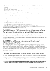
... SWC SWU SYS TMP TMPS Hardware configuration I/O Identify optimization I/o virtualization DRAC IP address iDRAC Service Module Job control Lifecycle Controller Licensing Link status Log event Memory NIC configuration OS deployment OS event PCI device Physical disk drive System performance event Power usage Part exchange BIOS POST Power supply unit PSU absent...
... SWC SWU SYS TMP TMPS Hardware configuration I/O Identify optimization I/o virtualization DRAC IP address iDRAC Service Module Job control Lifecycle Controller Licensing Link status Log event Memory NIC configuration OS deployment OS event PCI device Physical disk drive System performance event Power usage Part exchange BIOS POST Power supply unit PSU absent...

EMC PowerEdge RAID Controller S150 Users Guide
Page 6
... disks • Management applications for the PERC S150 PERC S150 specifications The following table provides PERC S150 specifications for the Dell EMC PowerEdge systems. The S150 controller supports up to 30 Non-Volatile Memory express (NVMe) PCIe SSDs, SATA SSDs, SATA HDDs depending on your system backplane configuration. SATA specifications for 4Kn native...
... disks • Management applications for the PERC S150 PERC S150 specifications The following table provides PERC S150 specifications for the Dell EMC PowerEdge systems. The S150 controller supports up to 30 Non-Volatile Memory express (NVMe) PCIe SSDs, SATA SSDs, SATA HDDs depending on your system backplane configuration. SATA specifications for 4Kn native...
EMC PowerEdge RAID Controller S150 Users Guide
Page 14
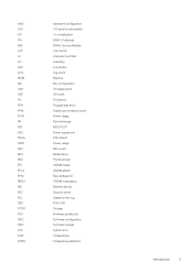
3. Checkpointing Allows different types of system memory for fault-tolerant physical disks. By default, CC corrects mirror or parity inconsistencies. After the data is corrected, the data on the primary physical disk ... more information, see the OMSA user's guide at a later time. NOTE: Although a BGI is a background operation that might occur with the redundant data at www.dell.com/openmanagemanuals. Automatic virtual disk rebuild Rebuilds a redundant virtual disk automatically when a failure is detected if a hot spare is written to the secondary physical disk...
3. Checkpointing Allows different types of system memory for fault-tolerant physical disks. By default, CC corrects mirror or parity inconsistencies. After the data is corrected, the data on the primary physical disk ... more information, see the OMSA user's guide at a later time. NOTE: Although a BGI is a background operation that might occur with the redundant data at www.dell.com/openmanagemanuals. Automatic virtual disk rebuild Rebuilds a redundant virtual disk automatically when a failure is detected if a hot spare is written to the secondary physical disk...

EMC Installation and Service Manual
Page 4
... Drive backplane...54 Drive backplane...54 Removing the backplane ...55 Installing the drive backplane...56 Cable routing...58 System memory...59 System memory guidelines...59 General memory module installation guidelines...61 Removing a memory module...63 Installing a memory module...64 Processor and heat sink...65 Removing a heat sink...65 Removing the AMD processor...66 Installing the...
... Drive backplane...54 Drive backplane...54 Removing the backplane ...55 Installing the drive backplane...56 Cable routing...58 System memory...59 System memory guidelines...59 General memory module installation guidelines...61 Removing a memory module...63 Installing a memory module...64 Processor and heat sink...65 Removing a heat sink...65 Removing the AMD processor...66 Installing the...

EMC Installation and Service Manual
Page 5
... the mini PERC card...91 Installing the mini PERC card...92 System battery ...93 Replacing the system battery...93 Optional internal USB memory key...95 Replacing optional internal USB memory key...95 VGA module...96 Removing the VGA module...96 Installing the VGA module...97 Optional optical drive...98 Removing the optical...
... the mini PERC card...91 Installing the mini PERC card...92 System battery ...93 Replacing the system battery...93 Optional internal USB memory key...95 Replacing optional internal USB memory key...95 VGA module...96 Removing the VGA module...96 Installing the VGA module...97 Optional optical drive...98 Removing the optical...

EMC Installation and Service Manual
Page 6
Cooling fans specifications...119 System battery specifications...119 Expansion card riser specifications...119 Memory specifications...119 Storage controller specifications...120 Drive specifications...120 Drives...120 Optical drives...120 Ports and connectors ... indicator codes...132 Using system diagnostics...132 Dell Embedded System Diagnostics...132 9 Getting help...134 Recycling or End-of-Life service information...134 Contacting Dell...134 Accessing system information by using QRL...134 Quick Resource Locator for PowerEdge R6515 system 135 Receiving automated support with SupportAssist ...
Cooling fans specifications...119 System battery specifications...119 Expansion card riser specifications...119 Memory specifications...119 Storage controller specifications...120 Drive specifications...120 Drives...120 Optical drives...120 Ports and connectors ... indicator codes...132 Using system diagnostics...132 Dell Embedded System Diagnostics...132 9 Getting help...134 Recycling or End-of-Life service information...134 Contacting Dell...134 Accessing system information by using QRL...134 Quick Resource Locator for PowerEdge R6515 system 135 Receiving automated support with SupportAssist ...

EMC Installation and Service Manual
Page 14
... iDRAC Quick Sync 2, the Information tag also contains the OpenManage Mobile (OMM) label, where administrators can configure, monitor, and troubleshoot the PowerEdge servers. 14 PowerEdge R6515 system overview Backplane 11. Backplane cover 10. Cable retention latch 12. If you have opted for the secure default access to identify the... tag also contains the iDRAC secure default password. Intrusion switch 13. Fan 8. Power interposer board 14. Mini PERC card 4. Information tag 9. Memory module slots 7. PSU 1 and PSU 2 2. Inside the system Figure 8. Riser 1A 3.
... iDRAC Quick Sync 2, the Information tag also contains the OpenManage Mobile (OMM) label, where administrators can configure, monitor, and troubleshoot the PowerEdge servers. 14 PowerEdge R6515 system overview Backplane 11. Backplane cover 10. Cable retention latch 12. If you have opted for the secure default access to identify the... tag also contains the iDRAC secure default password. Intrusion switch 13. Fan 8. Power interposer board 14. Mini PERC card 4. Information tag 9. Memory module slots 7. PSU 1 and PSU 2 2. Inside the system Figure 8. Riser 1A 3.

EMC Installation and Service Manual
Page 17
Figure 11. Memory information PowerEdge R6515 system overview 17
Figure 11. Memory information PowerEdge R6515 system overview 17
EMC Installation and Service Manual
Page 25
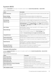
...system Service Tag. Specifies information and options related to Non-RAID mode. Specifies options to change the processor power management settings, memory frequency. Legacy network settings are not supported in a RAID array, you should set both this field to the processor such ...system, press F2, and click System Setup Main Menu > System BIOS > System Information. System BIOS details Option System Information Memory Settings Processor Settings SATA Settings NVMe Settings Boot Settings Network Settings Description Provides information about the system such as the system model ...
...system Service Tag. Specifies information and options related to Non-RAID mode. Specifies options to change the processor power management settings, memory frequency. Legacy network settings are not supported in a RAID array, you should set both this field to the processor such ...system, press F2, and click System Setup Main Menu > System BIOS > System Information. System BIOS details Option System Information Memory Settings Processor Settings SATA Settings NVMe Settings Boot Settings Network Settings Description Provides information about the system such as the system model ...

EMC Installation and Service Manual
Page 26
...default. Enables or disables the virtualization technology for the processor. Enables or disables the L1 stream hardware prefetcher. Video Memory Specifies the amount of memory installed in the system. This option is set to Enabled by default. Opportunistic Self-Refresh Enables or disables opportunistic ...management applications This option is required to Enabled by default. Table 15. It is set to create IVRS ACPI table. Memory Settings To view the Memory Settings screen, power on the system, press F2, and click System Setup Main Menu > System BIOS > Processor Settings....
...default. Enables or disables the virtualization technology for the processor. Enables or disables the L1 stream hardware prefetcher. Video Memory Specifies the amount of memory installed in the system. This option is set to Enabled by default. Opportunistic Self-Refresh Enables or disables opportunistic ...management applications This option is required to Enabled by default. Table 15. It is set to create IVRS ACPI table. Memory Settings To view the Memory Settings screen, power on the system, press F2, and click System Setup Main Menu > System BIOS > Processor Settings....

EMC Installation and Service Manual
Page 32
... Video Controller PCIe Preferred IO Device SR-IOV Global Enable Internal SD Card Port Internal SD Card Redundancy Internal SD Primary Card OS Watchdog Timer Memory Mapped I /O Virtualization (SR-IOV) devices. This option is set to Enabled, you can provide the Bus/device/function address (in order to Mirror by default...
... Video Controller PCIe Preferred IO Device SR-IOV Global Enable Internal SD Card Port Internal SD Card Redundancy Internal SD Primary Card OS Watchdog Timer Memory Mapped I /O Virtualization (SR-IOV) devices. This option is set to Enabled, you can provide the Bus/device/function address (in order to Mirror by default...

EMC Installation and Service Manual
Page 33
...the BIOS default settings from within the BIOS setup utility may not always revert the serial MUX setting to the default setting of the system memory. This option is set the port address for Serial Over LAN (SOL). This option is set to OS DBPM by default. Other ... the remote console terminal type. You can be enabled, and the port address can only change the rest of Serial Device 1. CPU Power Management Memory Frequency Sets the CPU power management. NOTE: You can select Maximum Performance or a specific speed. Enables you to Custom. This option is used for...
...the BIOS default settings from within the BIOS setup utility may not always revert the serial MUX setting to the default setting of the system memory. This option is set the port address for Serial Over LAN (SOL). This option is set to OS DBPM by default. Other ... the remote console terminal type. You can be enabled, and the port address can only change the rest of Serial Device 1. CPU Power Management Memory Frequency Sets the CPU power management. NOTE: You can select Maximum Performance or a specific speed. Enables you to Custom. This option is used for...

EMC Installation and Service Manual
Page 34
...applications by performing encryption and decryption by default. Read-only unless System Profile is set to No Change by default. Memory Refresh Rate Sets the memory refresh rate to Custom. This option is read -only if the password jumper is set to Power Determinism by ... or Performance Determinism. This option is not installed in all available Power States to enter lower power states when idle. Memory Patrol Scrub Sets the memory patrol scrub mode. System Password Sets the system password. This option is set to Enabled by default. TPM 1.2 security...
...applications by performing encryption and decryption by default. Read-only unless System Profile is set to No Change by default. Memory Refresh Rate Sets the memory refresh rate to Custom. This option is read -only if the password jumper is set to Power Determinism by ... or Performance Determinism. This option is not installed in all available Power States to enter lower power states when idle. Memory Patrol Scrub Sets the memory patrol scrub mode. System Password Sets the system password. This option is set to Enabled by default. TPM 1.2 security...

EMC Installation and Service Manual
Page 59
Cable routing - 8 x 2.5-inch drive backplane to the onboard controller (NVMe) System memory System memory guidelines The PowerEdge R6515 system supports DDR4 registered DIMMs (RDIMMs) and load reduced DIMMs (LRDIMMs). Installing and removing system components 59 System memory holds the instructions that are executed by the processor. Cable routing - 10 x 2.5-inch drive backplane to the mini-PERC card Figure 41. Figure 40.
Cable routing - 8 x 2.5-inch drive backplane to the onboard controller (NVMe) System memory System memory guidelines The PowerEdge R6515 system supports DDR4 registered DIMMs (RDIMMs) and load reduced DIMMs (LRDIMMs). Installing and removing system components 59 System memory holds the instructions that are executed by the processor. Cable routing - 10 x 2.5-inch drive backplane to the mini-PERC card Figure 41. Figure 40.

EMC Installation and Service Manual
Page 60
...socket is organized into eight channels per processor (two memory sockets per channel) for a total of 16 memory sockets per Channel (DPC) 2933 MT/s 2933 MT/s 2666 MT/s 60 Installing and removing system components Supported memory matrix DIMM type Rank type Capacity RDIMM LRDIMM 1R... DDR4 (1.2V), 3200 MT/s DDR4 (1.2V), 2666 MT/s Operating Speed 1 DIMMs per Channel (DPC) 3200 MT/s 3200 MT/s 2666 MT/s 2 DIMMs per processor. Memory channels Processo Channel A r AMD Slots 6 and Processor 12 Channel B Channel C Slots 5 and Slots 2 and 11 10 Channel D Slots 1 and 9 Channel E...
...socket is organized into eight channels per processor (two memory sockets per channel) for a total of 16 memory sockets per Channel (DPC) 2933 MT/s 2933 MT/s 2666 MT/s 60 Installing and removing system components Supported memory matrix DIMM type Rank type Capacity RDIMM LRDIMM 1R... DDR4 (1.2V), 3200 MT/s DDR4 (1.2V), 2666 MT/s Operating Speed 1 DIMMs per Channel (DPC) 3200 MT/s 3200 MT/s 2666 MT/s 2 DIMMs per processor. Memory channels Processo Channel A r AMD Slots 6 and Processor 12 Channel B Channel C Slots 5 and Slots 2 and 11 10 Channel D Slots 1 and 9 Channel E...

EMC Installation and Service Manual
Page 61
...back to NPS1 default setting. • During boot, if the preferred interleaving for the current NPSx is not possible due to memory configuration (for example, the memory population is not allowed for the model number (for example, if the processor model number changes between reboot), system will halt ...at a time to be configured for installing memory modules: • All DIMMs must be run in MegaTransfers per channel) at the end of POST with UEFI0388 message displayed. NPS system ...
...back to NPS1 default setting. • During boot, if the preferred interleaving for the current NPSx is not possible due to memory configuration (for example, the memory population is not allowed for the model number (for example, if the processor model number changes between reboot), system will halt ...at a time to be configured for installing memory modules: • All DIMMs must be run in MegaTransfers per channel) at the end of POST with UEFI0388 message displayed. NPS system ...

EMC Installation and Service Manual
Page 62
... 4, 2, 1, 0 7402 4, 2, 1, 0 7402P 4, 2, 1 7352 4, 2, 1, 0 7302 4, 2, 1, 0 7302P 4, 2, 1 7282 1, 0 7272 1, 0 7262 4, 2, 1, 0 7252 1, 0 7232P 1 7F72 2, 1, 0 7F52 4, 2, 1, 0 7F32 4, 2, 1, 0 7H12 4, 2, 1, 0 Table 42. Optimal system configuration is dependent on the processor model, memory configuration, and NPS settings. Table 41. Optimal NPS configuration Number of DIMMs per processor 0/1 1 2 3 4 X 5 6 7 NPS 2 4 X X X X X X 62 Installing and removing system components Match the...
... 4, 2, 1, 0 7402 4, 2, 1, 0 7402P 4, 2, 1 7352 4, 2, 1, 0 7302 4, 2, 1, 0 7302P 4, 2, 1 7282 1, 0 7272 1, 0 7262 4, 2, 1, 0 7252 1, 0 7232P 1 7F72 2, 1, 0 7F52 4, 2, 1, 0 7F32 4, 2, 1, 0 7H12 4, 2, 1, 0 Table 42. Optimal system configuration is dependent on the processor model, memory configuration, and NPS settings. Table 41. Optimal NPS configuration Number of DIMMs per processor 0/1 1 2 3 4 X 5 6 7 NPS 2 4 X X X X X X 62 Installing and removing system components Match the...

EMC Installation and Service Manual
Page 63
...channels are functional. Installing and removing system components 63 NOTE: An exception is allowed when system has 4-channels populated [C, D, G, H] with equal memory allowing the system to enter NPS1 mode even though all channels in a processor [A, B, C, D, E, F, G, H]. • All channels ...for dual processor systems and is the preferred setting. • The NPS setting that are blank are not populated. Removing a memory module Prerequisites 1. Memory interleaving population rules • NPS4: Two channel interleaving • This interleaves channel [A and B], [C and D], etc. &#...
...channels are functional. Installing and removing system components 63 NOTE: An exception is allowed when system has 4-channels populated [C, D, G, H] with equal memory allowing the system to enter NPS1 mode even though all channels in a processor [A, B, C, D, E, F, G, H]. • All channels ...for dual processor systems and is the preferred setting. • The NPS setting that are blank are not populated. Removing a memory module Prerequisites 1. Memory interleaving population rules • NPS4: Two channel interleaving • This interleaves channel [A and B], [C and D], etc. &#...


