Glossary
Page 9
... physical system may be integrated into an expansion slot. Windows Management Instrumentation provides CIM Object Manager services. Volt(s). Video graphics array. Watt(s). WH - A program used to your system's RAM. VDC - VGA and SVGA are video standards for example. video adapter - The amount of video memory installed primarily influences the number of pixels...
... physical system may be integrated into an expansion slot. Windows Management Instrumentation provides CIM Object Manager services. Volt(s). Video graphics array. Watt(s). WH - A program used to your system's RAM. VDC - VGA and SVGA are video standards for example. video adapter - The amount of video memory installed primarily influences the number of pixels...

Getting Started Guide
Page 11
... or 1333 MHz DDR3 registered or unbuffered Error Correcting Code (ECC) DIMMs Memory module sockets Eight 240-pin Memory module capacities Four-hard-drive systems Eight-hard-drive systems Twelve-hard-drive systems 1 GB, 2 GB, or 4 GB 1 GB, 2 GB, 4 GB, or 8 GB 1 GB...connectors. and quad-rank DIMMs) 64 GB (8 GB dual- Riser 1 OR Riser 2 Slot 1: PCIe x4, half-length, full-height Slot 2: PCIe x4, full-length, full-height Slot 3: PCIe x8, half-length, full-height Slot 4: PCIe x4, internal slot for integrated card NOTE: A General Purpose Computation on Graphics Processing Units (GPGPU) optimized ...
... or 1333 MHz DDR3 registered or unbuffered Error Correcting Code (ECC) DIMMs Memory module sockets Eight 240-pin Memory module capacities Four-hard-drive systems Eight-hard-drive systems Twelve-hard-drive systems 1 GB, 2 GB, or 4 GB 1 GB, 2 GB, 4 GB, or 8 GB 1 GB...connectors. and quad-rank DIMMs) 64 GB (8 GB dual- Riser 1 OR Riser 2 Slot 1: PCIe x4, half-length, full-height Slot 2: PCIe x4, full-length, full-height Slot 3: PCIe x8, half-length, full-height Slot 4: PCIe x4, internal slot for integrated card NOTE: A General Purpose Computation on Graphics Processing Units (GPGPU) optimized ...

Hardware Owner's Manual
Page 23
...riser 1 or riser 2. Connects four PCI Express Generation 2 expansion cards NOTE: All four slots are USB 2.0-compliant. Connects an external SD memory card for the optional iDRAC6 Enterprise card. Connects two PCI Express Generation 2 expansion cards. ...Button, or Icon Connector 1 Serial connector 2 Video connector 3 iDRAC6 Enterprise port (optional) 4 VFlash media slot (optional) 5 USB connectors (2) 6 Ethernet connectors (2) 7 PCIe expansion card slots using riser card Riser 1 OR Riser 2 8 System identification connector Description Connects a serial device to the ...
...riser 1 or riser 2. Connects four PCI Express Generation 2 expansion cards NOTE: All four slots are USB 2.0-compliant. Connects an external SD memory card for the optional iDRAC6 Enterprise card. Connects two PCI Express Generation 2 expansion cards. ...Button, or Icon Connector 1 Serial connector 2 Video connector 3 iDRAC6 Enterprise port (optional) 4 VFlash media slot (optional) 5 USB connectors (2) 6 Ethernet connectors (2) 7 PCIe expansion card slots using riser card Riser 1 OR Riser 2 8 System identification connector Description Connects a serial device to the ...
Hardware Owner's Manual
Page 39
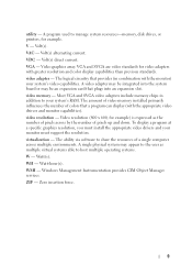
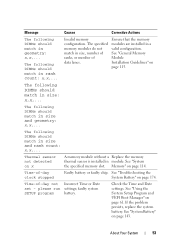
...and does not log anymore SBEs until the system is rebooted. Code Text Causes Corrective Actions E2021 Incorrect Incorrect memory memory configuration. configuration. Review User Guide. E2022 General failure during POST. Check screen message. Check screen for ...BIOS could mirror memory. See "Troubleshooting System Memory" on DIMM ##. slot "##" has had too many If the problem persists, errors. multi-bit error (MBE). "##" represents the memory module implicated by the BIOS. If the problem persists, see "Troubleshooting memory module System Memory" on page ...
...and does not log anymore SBEs until the system is rebooted. Code Text Causes Corrective Actions E2021 Incorrect Incorrect memory memory configuration. configuration. Review User Guide. E2022 General failure during POST. Check screen message. Check screen for ...BIOS could mirror memory. See "Troubleshooting System Memory" on DIMM ##. slot "##" has had too many If the problem persists, errors. multi-bit error (MBE). "##" represents the memory module implicated by the BIOS. If the problem persists, see "Troubleshooting memory module System Memory" on page ...

Hardware Owner's Manual
Page 45
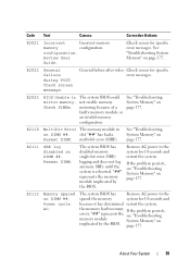
... an intentional setting, intentionally set to the default position (pins 3 and 5). NVRAM_CLR jumper is installed in the indicated processor's memory slots. Please run SETUP NVRAM_CLR jumper is installed on page 114. Install memory modules for jumper location. Message Causes Corrective Actions BIOS Update Remote BIOS update Attempt Failed! attempt failed. See "Using the...
... an intentional setting, intentionally set to the default position (pins 3 and 5). NVRAM_CLR jumper is installed in the indicated processor's memory slots. Please run SETUP NVRAM_CLR jumper is installed on page 114. Install memory modules for jumper location. Message Causes Corrective Actions BIOS Update Remote BIOS update Attempt Failed! attempt failed. See "Using the...
Hardware Owner's Manual
Page 47
... or keyboard. Gate A20 failure Faulty keyboard controller; Invalid configuration information please run SETUP program. dedicated storage controller slot. Invalid memory configuration on page 146. Error 8602 Auxiliary Device Failure. page 199. See "RAID Battery (Optional)" on a.... Remove the PCIe expansion card and install the integrated storage controller in management tools. The memory module configuration for NIC settings. The Management OS NIC=, in the dedicated slot. If a problem is loose or improperly connected. Mouse or keyboard cable is indicated, see...
... or keyboard. Gate A20 failure Faulty keyboard controller; Invalid configuration information please run SETUP program. dedicated storage controller slot. Invalid memory configuration on page 146. Error 8602 Auxiliary Device Failure. page 199. See "RAID Battery (Optional)" on a.... Remove the PCIe expansion card and install the integrated storage controller in management tools. The memory module configuration for NIC settings. The Management OS NIC=, in the dedicated slot. If a problem is loose or improperly connected. Mouse or keyboard cable is indicated, see...

Hardware Owner's Manual
Page 52
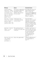
...faulty. The BIOS setting has been disabled. See "Getting Help" on page 177. 52 About Your System See "System Memory" on page 181 for Memory Sparing mode. If memory has not been added or removed, check the SEL to determine if single-bit or multi-bit errors were detected and ...that the USB or SAS backplane cables are properly connected. The amount of three must be ignored. If memory has been added or removed, this message is informative and can be populated across slots. Message Causes Sector not found Faulty hard drive, USB Seek error device, or USB medium. See "...
...faulty. The BIOS setting has been disabled. See "Getting Help" on page 177. 52 About Your System See "System Memory" on page 181 for Memory Sparing mode. If memory has not been added or removed, check the SEL to determine if single-bit or multi-bit errors were detected and ...that the USB or SAS backplane cables are properly connected. The amount of three must be ignored. If memory has been added or removed, this message is informative and can be populated across slots. Message Causes Sector not found Faulty hard drive, USB Seek error device, or USB medium. See "...
Hardware Owner's Manual
Page 53
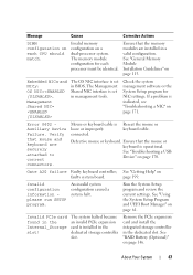
...match in module. See "System the specified memory slot. Memory" on page 115. See "General Memory Module Installation Guidelines" on page 114. See "Using the System Setup Program and UEFI Boot Manager" on x A memory module without a Replace the memory thermal sensor is installed in size: x,x,... ...-day not Incorrect Time or Date set - Time-of -day clock stopped Faulty battery or faulty chip. Invalid memory configuration. The specified memory modules do not match in a valid configuration. The following DIMMs should match in size and geometry: x,x,... Thermal ...
...match in module. See "System the specified memory slot. Memory" on page 115. See "General Memory Module Installation Guidelines" on page 114. See "Using the System Setup Program and UEFI Boot Manager" on x A memory module without a Replace the memory thermal sensor is installed in size: x,x,... ...-day not Incorrect Time or Date set - Time-of -day clock stopped Faulty battery or faulty chip. Invalid memory configuration. The specified memory modules do not match in a valid configuration. The following DIMMs should match in size and geometry: x,x,... Thermal ...

Hardware Owner's Manual
Page 55
... combination Unsupported CPU stepping detected Processor(s) is not optimal for Memory Mirroring Mode, or change the memory mode to Optimized or Sparing in the mirroring Mode. Reseat the memory modules. See "Processors" on page 114. The following slot Modules in the specified slots. See "System Memory" on page 138. Message Causes Corrective Actions Unexpected interrupt in...
... combination Unsupported CPU stepping detected Processor(s) is not optimal for Memory Mirroring Mode, or change the memory mode to Optimized or Sparing in the mirroring Mode. Reseat the memory modules. See "Processors" on page 114. The following slot Modules in the specified slots. See "System Memory" on page 138. Message Causes Corrective Actions Unexpected interrupt in...
Hardware Owner's Manual
Page 56
... the system board. code update loaded for detected. Message Causes Corrective Actions Unused memory The memory configuration is Reconfigure the memory for processor n Update the BIOS firmware. See "Getting Help" on page 114. system to Optimized are not available slots are unused. Check the SEL for any faulty components specified in "Troubleshooting Your System...
... the system board. code update loaded for detected. Message Causes Corrective Actions Unused memory The memory configuration is Reconfigure the memory for processor n Update the BIOS firmware. See "Getting Help" on page 114. system to Optimized are not available slots are unused. Check the SEL for any faulty components specified in "Troubleshooting Your System...

Hardware Owner's Manual
Page 116
... of the total installed physical memory. This mode supports Single Device Data Correction (SDDC) for both x4- In a mirrored configuration, the total available system memory is also supported in corresponding slots. This mode permits a larger total memory capacity but does not support SDDC... with different speeds are mixed with identical memory modules. Mirroring must be identical in size, speed, and...
... of the total installed physical memory. This mode supports Single Device Data Correction (SDDC) for both x4- In a mirrored configuration, the total available system memory is also supported in corresponding slots. This mode permits a larger total memory capacity but does not support SDDC... with different speeds are mixed with identical memory modules. Mirroring must be identical in size, speed, and...

Hardware Owner's Manual
Page 122
... end of the socket until the memory module pops out of the memory module. 6 Replace the cooling shroud. See "Installing the Cooling Shroud" on the expansion-card riser. Expansion Card Installation Guidelines • The expansion-card slots support full-height, half-length cards. • The expansion-card slots are hot-swappable. • PCI Express...
... end of the socket until the memory module pops out of the memory module. 6 Replace the cooling shroud. See "Installing the Cooling Shroud" on the expansion-card riser. Expansion Card Installation Guidelines • The expansion-card slots support full-height, half-length cards. • The expansion-card slots are hot-swappable. • PCI Express...
Hardware Owner's Manual
Page 137
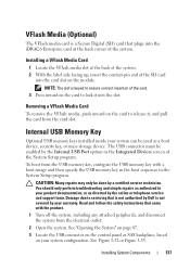
... of the system. 2 With the label side facing up, insert the contact-pin end of the System Setup program. Internal USB Memory Key Optional USB memory keys installed inside your product documentation, or as a boot device, security key, or mass storage device. Installing System Components 137 Removing... program. Read and follow the safety instructions that is not authorized by Dell is not covered by the online or telephone service and support team. Installing a VFlash Media Card 1 Locate the VFlash media slot at the back corner of the system. CAUTION: Many repairs may only...
... of the system. 2 With the label side facing up, insert the contact-pin end of the System Setup program. Internal USB Memory Key Optional USB memory keys installed inside your product documentation, or as a boot device, security key, or mass storage device. Installing System Components 137 Removing... program. Read and follow the safety instructions that is not authorized by Dell is not covered by the online or telephone service and support team. Installing a VFlash Media Card 1 Locate the VFlash media slot at the back corner of the system. CAUTION: Many repairs may only...

Hardware Owner's Manual
Page 148
Removing and Installing the Control Panel-LED (Four-Hard-Drive System) 1 8 2 7 3 6 1 control panel cable 3 power cable 5 LED display module 7 control panel board 4 5 2 USB memory key connector 4 standoff 6 slot 8 mounting screws (2) 148 Installing System Components Figure 3-30.
Removing and Installing the Control Panel-LED (Four-Hard-Drive System) 1 8 2 7 3 6 1 control panel cable 3 power cable 5 LED display module 7 control panel board 4 5 2 USB memory key connector 4 standoff 6 slot 8 mounting screws (2) 148 Installing System Components Figure 3-30.

Hardware Owner's Manual
Page 153
See Figure 3-32. 7 Remove the two Phillips screws that secure the control panel board to the system chassis and remove the board. Removing and Installing the Control Panel-LCD 1 2 3 4 1 slot 3 USB memory key connector 5 control panel board 7 LCD display module 5 7 6 2 control panel cable 4 power cable 6 display module cable Installing System Components 153 Figure 3-32. 6 Disconnect the display module cable from the control panel board.
See Figure 3-32. 7 Remove the two Phillips screws that secure the control panel board to the system chassis and remove the board. Removing and Installing the Control Panel-LCD 1 2 3 4 1 slot 3 USB memory key connector 5 control panel board 7 LCD display module 5 7 6 2 control panel cable 4 power cable 6 display module cable Installing System Components 153 Figure 3-32. 6 Disconnect the display module cable from the control panel board.

Hardware Owner's Manual
Page 208
.... video adapter - system memory - UPS - A battery-powered unit that provides (in the event of an electrical failure. A USB connector provides a single connection point for the devices. V - Video graphics array. A video adapter may be integrated into an expansion slot. 208 Glossary A BIOS-.... termination - Volt(s) direct current. uplink port - VGA and SVGA are connected in a series, you to manage system resources-memory, disk drives, or printers, for video adapters with the monitor) your system's hardware and customize the system's operation by changing ...
.... video adapter - system memory - UPS - A battery-powered unit that provides (in the event of an electrical failure. A USB connector provides a single connection point for the devices. V - Video graphics array. A video adapter may be integrated into an expansion slot. 208 Glossary A BIOS-.... termination - Volt(s) direct current. uplink port - VGA and SVGA are connected in a series, you to manage system resources-memory, disk drives, or printers, for video adapters with the monitor) your system's hardware and customize the system's operation by changing ...
Hardware Owner's Manual
Page 212
... using Dell PowerEdge Diagnostics, 189 when to use, 190 DIMMs See memory modules (DIMMs). drive blank installing, 92 removing, 91 E Embedded System Management, 79 error messages, 62 expansion card troubleshooting, 184 expansion cards installing, 124 removing, 126 SAS controller, 129 expansion slots, 122... F front-panel features, 14 G guidelines 212 Index connecting external devices, 25 expansion card installation, 122 memory installation, 115 H hard drive troubleshooting, 181-182 hard drives (cabled)...
... using Dell PowerEdge Diagnostics, 189 when to use, 190 DIMMs See memory modules (DIMMs). drive blank installing, 92 removing, 91 E Embedded System Management, 79 error messages, 62 expansion card troubleshooting, 184 expansion cards installing, 124 removing, 126 SAS controller, 129 expansion slots, 122... F front-panel features, 14 G guidelines 212 Index connecting external devices, 25 expansion card installation, 122 memory installation, 115 H hard drive troubleshooting, 181-182 hard drives (cabled)...

Hardware Owner's Manual
Page 214
... SATA hard drive. startup accessing system features, 13 214 Index SD card troubleshooting, 179 securing your system, 71, 77 setup password, 78 slots See expansion slots. POST accessing system features, 13 power indicators, 14, 26 power supplies indicators, 26 removing, 110, 112 replacing, 111, 114 power supply...assembly, 147, 149, 152, 154 cooling shroud, 90 cover, 87 expansion card, 126 hard drive (cabled), 95-96 hard drive blank, 91 memory modules, 121 power supply, 110, 112 power supply blank, 112 processor, 138 SAS backplane board, 156 SAS controller, 129 system board, 165 replacing...
... SATA hard drive. startup accessing system features, 13 214 Index SD card troubleshooting, 179 securing your system, 71, 77 setup password, 78 slots See expansion slots. POST accessing system features, 13 power indicators, 14, 26 power supplies indicators, 26 removing, 110, 112 replacing, 111, 114 power supply...assembly, 147, 149, 152, 154 cooling shroud, 90 cover, 87 expansion card, 126 hard drive (cabled), 95-96 hard drive blank, 91 memory modules, 121 power supply, 110, 112 power supply blank, 112 processor, 138 SAS backplane board, 156 SAS controller, 129 system board, 165 replacing...


