
Glossary
Page 1
...if the system will not boot from SNMP agents. The modules are mounted into a chassis that contains a processor, memory, and a hard drive. BMC - Baseboard management controller. C - A fast storage area that keeps a copy of data or instructions for enabling the operating ... connected to communicate with MIB data from the hard drive. Ampere(s). An information pathway between the processor and RAM. Alternating current. ambient temperature - bootable media - A module that includes power supplies and fans. Dell™ Glossary NOTE: For additional information on ...
...if the system will not boot from SNMP agents. The modules are mounted into a chassis that contains a processor, memory, and a hard drive. BMC - Baseboard management controller. C - A fast storage area that keeps a copy of data or instructions for enabling the operating ... connected to communicate with MIB data from the hard drive. Ampere(s). An information pathway between the processor and RAM. Alternating current. ambient temperature - bootable media - A module that includes power supplies and fans. Dell™ Glossary NOTE: For additional information on ...

Glossary
Page 3
...for connection of file storage. IDE - iDRAC - InfiniBand offers point-to insert or install a device, typically a hard drive or an internal cooling fan, into the host system while the system is usually rounded to organize and keep track of... intended for plugging in an expansion card. Hertz. I /O activity can be programmed and reprogrammed using a software utility. Integrated drive electronics. Integrated Dell Remote Access Controller. Fibre Channel - Gravities. The Microsoft® Windows® operating systems can be differentiated from computational activity. ...
...for connection of file storage. IDE - iDRAC - InfiniBand offers point-to insert or install a device, typically a hard drive or an internal cooling fan, into the host system while the system is usually rounded to organize and keep track of... intended for plugging in an expansion card. Hertz. I /O activity can be programmed and reprogrammed using a software utility. Integrated drive electronics. Integrated Dell Remote Access Controller. Fibre Channel - Gravities. The Microsoft® Windows® operating systems can be differentiated from computational activity. ...

Glossary
Page 5
..., when referring to the system board. A small circuit board containing DRAM chips that is any system that connects to hard-drive capacity, the term is provided by software. memory key - MHz - Mirroring functionality is often rounded to a network.... data and one or more sets of additional drives stores duplicate copies of the data. Millimeter(s). Network Attached Storage. Network interface controller. MB - memory address - A managed system is monitored and managed using Dell OpenManage™ Server Administrator. Mbps - memory - Millisecond(s). ...
..., when referring to the system board. A small circuit board containing DRAM chips that is any system that connects to hard-drive capacity, the term is provided by software. memory key - MHz - Mirroring functionality is often rounded to a network.... data and one or more sets of additional drives stores duplicate copies of the data. Millimeter(s). Network Attached Storage. Network interface controller. MB - memory address - A managed system is monitored and managed using Dell OpenManage™ Server Administrator. Mbps - memory - Millisecond(s). ...

Glossary
Page 6
...processor. Nonmaskable interrupt. provider - NMI - You must usually be revised to a system. Each partition can divide a hard drive into multiple physical sections called partitions with a block of a CIM schema that communicates with multiple power outlets that does...RAM and hard drives. NVRAM - Memory that provides electrical power to servers and storage systems in rows and columns to signal the processor about hardware errors. Preboot eXecution Environment. Peripheral Component Interconnect. pixel - Nonvolatile random-access memory. PowerEdge RAID controller....
...processor. Nonmaskable interrupt. provider - NMI - You must usually be revised to a system. Each partition can divide a hard drive into multiple physical sections called partitions with a block of a CIM schema that communicates with multiple power outlets that does...RAM and hard drives. NVRAM - Memory that provides electrical power to servers and storage systems in rows and columns to signal the processor about hardware errors. Preboot eXecution Environment. Peripheral Component Interconnect. pixel - Nonvolatile random-access memory. PowerEdge RAID controller....

Glossary
Page 7
... to identify it when you turn off your system. read -only file is one bit at a time and is lost when you call Dell for program instructions and data. ROM - ROMB - A bar code label on the system used to connect a modem to the system BIOS... you turn off your system's boot routine and the POST. Storage Area Network. Serial Advanced Technology Attachment. Synchronous dynamic random-access memory. Allows hard drives to report errors and failures to the system. R-DIMM - A read -only file - Your system contains some programs essential to be locally attached...
... to identify it when you turn off your system. read -only file is one bit at a time and is lost when you call Dell for program instructions and data. ROM - ROMB - A bar code label on the system used to connect a modem to the system BIOS... you turn off your system's boot routine and the POST. Storage Area Network. Serial Advanced Technology Attachment. Synchronous dynamic random-access memory. Allows hard drives to report errors and failures to the system. R-DIMM - A read -only file - Your system contains some programs essential to be locally attached...
Getting Started Guide
Page 5
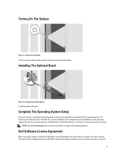
... supported operating systems. Dell Software License Agreement Before using your system. Turning on the System Press the power button on your operating system. Installing The Optional Bezel Figure 6. Complete The Operating System Setup If you do 5 Turning On The System Figure 5. To install an operating system for your system's hard drive. Be sure...
... supported operating systems. Dell Software License Agreement Before using your system. Turning on the System Press the power button on your operating system. Installing The Optional Bezel Figure 6. Complete The Operating System Setup If you do 5 Turning On The System Figure 5. To install an operating system for your system's hard drive. Be sure...
Owner's Manual
Page 3
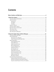
... Warnings 2 1 About Your System...9 Front-Panel Features And Indicators...9 LCD Panel Features...12 Home Screen...13 Setup Menu...13 View Menu...14 Diagnostic Indicators...14 Hard-Drive Indicator Patterns...16 Back-Panel Features And Indicators...17 NIC Indicator Codes...18 Power Indicator Codes...18 Other Information You May Need...19 2 Using The...
... Warnings 2 1 About Your System...9 Front-Panel Features And Indicators...9 LCD Panel Features...12 Home Screen...13 Setup Menu...13 View Menu...14 Diagnostic Indicators...14 Hard-Drive Indicator Patterns...16 Back-Panel Features And Indicators...17 NIC Indicator Codes...18 Power Indicator Codes...18 Other Information You May Need...19 2 Using The...
Owner's Manual
Page 4
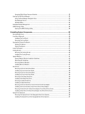
... Hard-Drive Blank...48 Installing A 2.5 Inch Hard-Drive Blank...49 Removing A 3.5 Inch Hard-Drive Blank...49 Installing A 3.5 Inch Hard-Drive Blank...49 Removing A Hot-Swap Hard Drive...49 Installing A Hot-Swap Hard Drive...50 Removing A Cabled Hard Drive...51 Installing A Cabled Hard Drive...52 Removing A 2.5 Inch Hard Drive From A 3.5 Inch Hard-Drive Adapter 52 Installing A 2.5 Inch Hard Drive Into A 3.5 Inch Hard-Drive Adapter 53 Removing A Hard Drive Or A Hard-Drive Adapter From A Hard-Drive Carrier 53 Installing A Hard Drive Or A Hard-Drive Adapter Into A Hard-Drive...
... Hard-Drive Blank...48 Installing A 2.5 Inch Hard-Drive Blank...49 Removing A 3.5 Inch Hard-Drive Blank...49 Installing A 3.5 Inch Hard-Drive Blank...49 Removing A Hot-Swap Hard Drive...49 Installing A Hot-Swap Hard Drive...50 Removing A Cabled Hard Drive...51 Installing A Cabled Hard Drive...52 Removing A 2.5 Inch Hard Drive From A 3.5 Inch Hard-Drive Adapter 52 Installing A 2.5 Inch Hard Drive Into A 3.5 Inch Hard-Drive Adapter 53 Removing A Hard Drive Or A Hard-Drive Adapter From A Hard-Drive Carrier 53 Installing A Hard Drive Or A Hard-Drive Adapter Into A Hard-Drive...
Owner's Manual
Page 5
Removing The Optical Drive In Cabled Hard-Drive Systems 58 Installing The Optical Drive In Cabled Hard-Drive Systems 59 Cooling Fans...60 Removing A Cooling Fan...60 Installing A Cooling Fan...61 Internal USB Memory Key (Optional)...62 Replacing The Internal USB Key...62 ... A Non-Redundant Power Supply...80 Removing The Power Supply Blank...81 Installing The Power Supply Blank...81 System Battery...81 Replacing The System Battery...81 Hard-Drive Backplane...82 Removing The Hard-Drive Backplane...83
Removing The Optical Drive In Cabled Hard-Drive Systems 58 Installing The Optical Drive In Cabled Hard-Drive Systems 59 Cooling Fans...60 Removing A Cooling Fan...60 Installing A Cooling Fan...61 Internal USB Memory Key (Optional)...62 Replacing The Internal USB Key...62 ... A Non-Redundant Power Supply...80 Removing The Power Supply Blank...81 Installing The Power Supply Blank...81 System Battery...81 Replacing The System Battery...81 Hard-Drive Backplane...82 Removing The Hard-Drive Backplane...83
Owner's Manual
Page 6
Installing The Hard-Drive Backplane...87 Control Panel Assembly...88 Removing The Control Panel...88 Installing The Control Panel...89 Removing The Control-Panel Module...90 Installing The Control-... Cooling Problems...104 Troubleshooting Cooling Fans...105 Troubleshooting System Memory...105 Troubleshooting An Internal USB Key...106 Troubleshooting An SD Card...106 Troubleshooting An Optical Drive...107 Troubleshooting A Tape Backup Unit...107 Troubleshooting A Hard Drive...108 Troubleshooting A Storage Controller...108 Troubleshooting Expansion Cards...109 Troubleshooting Processors...110
Installing The Hard-Drive Backplane...87 Control Panel Assembly...88 Removing The Control Panel...88 Installing The Control Panel...89 Removing The Control-Panel Module...90 Installing The Control-... Cooling Problems...104 Troubleshooting Cooling Fans...105 Troubleshooting System Memory...105 Troubleshooting An Internal USB Key...106 Troubleshooting An SD Card...106 Troubleshooting An Optical Drive...107 Troubleshooting A Tape Backup Unit...107 Troubleshooting A Hard Drive...108 Troubleshooting A Storage Controller...108 Troubleshooting Expansion Cards...109 Troubleshooting Processors...110
Owner's Manual
Page 9
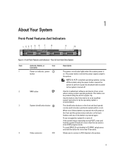
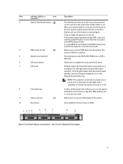
... system stops responding during POST, press and hold the button for more than five seconds to the system. Front-Panel Features and Indicators-Four 3.5 Inch Hard-Drive System Item Indicator, Button, or Icon Description Connector 1 Power-on indicator, power button The power-on indicator lights when the system power is pressed, the...
... system stops responding during POST, press and hold the button for more than five seconds to the system. Front-Panel Features and Indicators-Four 3.5 Inch Hard-Drive System Item Indicator, Button, or Icon Description Connector 1 Power-on indicator, power button The power-on indicator lights when the system power is pressed, the...
Owner's Manual
Page 10
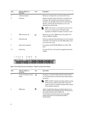
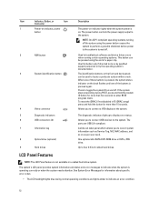
...can be pressed using the end of whether the system is turned on or off. 7 USB connectors (2) 8 Information tag 9 Optical drive (optional) 10 Hard drives Allows you to connect USB devices to the system. The ports are USB 2.0-compliant. Figure 2. Front-Panel Features and Indicators-Eight 2.5 ...Inch Hard-Drive System Item Indicator, Button, or Icon Description Connector 1 Power-on indicator, power button The power-on indicator lights when the ...
...can be pressed using the end of whether the system is turned on or off. 7 USB connectors (2) 8 Information tag 9 Optical drive (optional) 10 Hard drives Allows you to connect USB devices to the system. The ports are USB 2.0-compliant. Figure 2. Front-Panel Features and Indicators-Eight 2.5 ...Inch Hard-Drive System Item Indicator, Button, or Icon Description Connector 1 Power-on indicator, power button The power-on indicator lights when the ...
Owner's Manual
Page 11
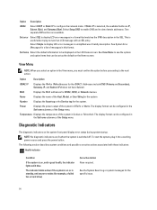
... menu buttons Allows you to connect a VGA display to the system. 10 Hard drives Up to eight 2.5 inch hard drives, or SSDs. Allows you to navigate the control panel LCD menu. 7 LCD panel Displays system ID, status information, and system error messages. Item Indicator, ... the system needs attention, and the LCD panel displays an error code followed by descriptive text. Front-Panel Features and Indicators-Four 3.5 Inch Cabled Hard-Drive System 11 The LCD lights blue during POST, press and hold the button for more than five seconds to enter BIOS progress mode. Figure 3. ...
... menu buttons Allows you to connect a VGA display to the system. 10 Hard drives Up to eight 2.5 inch hard drives, or SSDs. Allows you to navigate the control panel LCD menu. 7 LCD panel Displays system ID, status information, and system error messages. Item Indicator, ... the system needs attention, and the LCD panel displays an error code followed by descriptive text. Front-Panel Features and Indicators-Four 3.5 Inch Cabled Hard-Drive System 11 The LCD lights blue during POST, press and hold the button for more than five seconds to enter BIOS progress mode. Figure 3. ...
Owner's Manual
Page 12
...indicators light up to toggle the system ID on . One optional slim SATA DVD-ROM drive or DVD+/-RW drive. The power button controls the power supply output to four 3.5 inch cabled hard drives. If the system stops responding during POST, press and hold the button for information about... system power is on and off. The identification buttons on as per your need. To reset the iDRAC (if not disabled in a cabled hard-drive system. NOTE: On ACPI-compliant operating systems, turning off . 2 NMI button 3 System identification button 4 Video connector Used to troubleshoot software ...
...indicators light up to toggle the system ID on . One optional slim SATA DVD-ROM drive or DVD+/-RW drive. The power button controls the power supply output to four 3.5 inch cabled hard drives. If the system stops responding during POST, press and hold the button for information about... system power is on and off. The identification buttons on as per your need. To reset the iDRAC (if not disabled in a cabled hard-drive system. NOTE: On ACPI-compliant operating systems, turning off . 2 NMI button 3 System identification button 4 Video connector Used to troubleshoot software ...
Owner's Manual
Page 14
... Displays the IPv4 or IPv6 addresses for iDRAC, iSCSI, or Network devices. See the System Event Log or system messages for example, a failed fan or hard drive) Corrective Action None required.
... Displays the IPv4 or IPv6 addresses for iDRAC, iSCSI, or Network devices. See the System Event Log or system messages for example, a failed fan or hard drive) Corrective Action None required.
Owner's Manual
Page 15
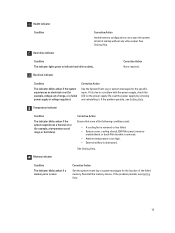
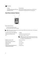
...required. Temperature indicator Condition The indicator blinks amber if the system experiences a thermal error (for the specific issue. Hard-drive indicator Condition The indicator lights green to halt at startup without any video output. If it . Health indicator Condition... Corrective Action Invalid memory configurations can cause the system to indicate hard-drive activity.. Corrective Action Ensure that none of range or fan failure). If the problem persists, see Getting Help. See Getting ...
...required. Temperature indicator Condition The indicator blinks amber if the system experiences a thermal error (for the specific issue. Hard-drive indicator Condition The indicator lights green to halt at startup without any video output. If it . Health indicator Condition... Corrective Action Invalid memory configurations can cause the system to indicate hard-drive activity.. Corrective Action Ensure that none of range or fan failure). If the problem persists, see Getting Help. See Getting ...
Owner's Manual
Page 16
... amber four times per second Off Condition Identifying drive or preparing for removal Drive ready for insertion or removal NOTE: The drive status indicator remains off six seconds Predicted drive failure Drive failed Drive rebuilding Drive online Rebuild aborted 16 Hard-Drive Indicators 1. Hard-Drive Indicator Patterns Figure 5. Corrective Action Restart the system. Drive-Status Indicator Pattern (RAID Only) Blinks green two...
... amber four times per second Off Condition Identifying drive or preparing for removal Drive ready for insertion or removal NOTE: The drive status indicator remains off six seconds Predicted drive failure Drive failed Drive rebuilding Drive online Rebuild aborted 16 Hard-Drive Indicators 1. Hard-Drive Indicator Patterns Figure 5. Corrective Action Restart the system. Drive-Status Indicator Pattern (RAID Only) Blinks green two...
Owner's Manual
Page 38
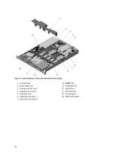
storage controller card 4. expansion card 6. optical drive 11. cable routing latch 38 DIMMs (12) 9. cooling shroud 2. power supply unit 3. cooling fans (5) 10. heat sink for processor 2 8. Figure 11. expansion-card riser 2 5. hard drives (4) 12. front I/O panel 13. expansion-card riser 1 7. Inside the System-With a Non-Redundant Power Supply 1.
storage controller card 4. expansion card 6. optical drive 11. cable routing latch 38 DIMMs (12) 9. cooling shroud 2. power supply unit 3. cooling fans (5) 10. heat sink for processor 2 8. Figure 11. expansion-card riser 2 5. hard drives (4) 12. front I/O panel 13. expansion-card riser 1 7. Inside the System-With a Non-Redundant Power Supply 1.
Owner's Manual
Page 39
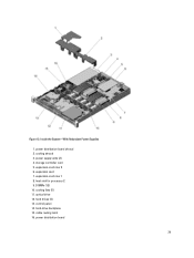
expansion-card riser 1 8. control panel 14. Figure 12. hard-drive backplane 15. expansion-card riser 2 6. DIMMs (12) 10. power supply units (2) 4. storage controller card 5. expansion card 7. optical drive 12. power distribution board 39 cooling fans (5) 11. cooling shroud 3. power distribution board shroud 2. cable routing latch 16. hard drives (4) 13. heat sink for processor 2 9. Inside the System-With Redundant Power Supplies 1.
expansion-card riser 1 8. control panel 14. Figure 12. hard-drive backplane 15. expansion-card riser 2 6. DIMMs (12) 10. power supply units (2) 4. storage controller card 5. expansion card 7. optical drive 12. power distribution board 39 cooling fans (5) 11. cooling shroud 3. power distribution board shroud 2. cable routing latch 16. hard drives (4) 13. heat sink for processor 2 9. Inside the System-With Redundant Power Supplies 1.
Owner's Manual
Page 47
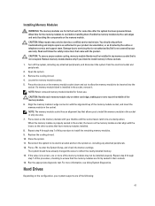
... with your product documentation, or as directed by Dell is not occupied. CAUTION: To ensure proper system cooling, memory-module blanks must be done by your system supports one way. 7. Remove the cooling shroud. 4. Align the memory module's edge connector with the product. Hard Drives Depending on the memory module with the levers...
... with your product documentation, or as directed by Dell is not occupied. CAUTION: To ensure proper system cooling, memory-module blanks must be done by your system supports one way. 7. Remove the cooling shroud. 4. Align the memory module's edge connector with the product. Hard Drives Depending on the memory module with the levers...


