
Glossary
Page 2
.... expansion bus - COMn - DC - A system's RAM is usually made up entirely of tests for example, handles numeric processing. Digital versatile disc or digital video disc. diagnostics - An add-in -line memory module. Double-data rate. A comprehensive set of DRAM chips. See also memory module. EMI -
.... expansion bus - COMn - DC - A system's RAM is usually made up entirely of tests for example, handles numeric processing. Digital versatile disc or digital video disc. diagnostics - An add-in -line memory module. Double-data rate. A comprehensive set of DRAM chips. See also memory module. EMI -

User Manual
Page 8
11 Reconnect your system and peripherals to their electrical outlets, and turn on the system. 12 Press to enter the System Setup and check that the processor information matches the new system configuration. 13 Run the system diagnostics to verify that the new processor operates correctly. 8 Additonal Processor Installation
11 Reconnect your system and peripherals to their electrical outlets, and turn on the system. 12 Press to enter the System Setup and check that the processor information matches the new system configuration. 13 Run the system diagnostics to verify that the new processor operates correctly. 8 Additonal Processor Installation
Owner's Manual
Page 3
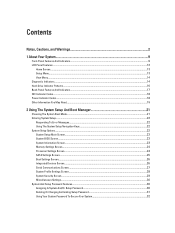
... Notes, Cautions, and Warnings 2 1 About Your System...9 Front-Panel Features And Indicators...9 LCD Panel Features...12 Home Screen...13 Setup Menu...13 View Menu...14 Diagnostic Indicators...14 Hard-Drive Indicator Patterns...16 Back-Panel Features And Indicators...17 NIC Indicator Codes...18 Power Indicator Codes...18 Other Information You May...
... Notes, Cautions, and Warnings 2 1 About Your System...9 Front-Panel Features And Indicators...9 LCD Panel Features...12 Home Screen...13 Setup Menu...13 View Menu...14 Diagnostic Indicators...14 Hard-Drive Indicator Patterns...16 Back-Panel Features And Indicators...17 NIC Indicator Codes...18 Power Indicator Codes...18 Other Information You May...
Owner's Manual
Page 7
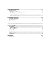
5 Using System Diagnostics...111 Dell Online Diagnostics...111 Dell Embedded System Diagnostics...111 When To Use The Embedded System Diagnostics 111 Running The Embedded System Diagnostics 111 System Diagnostic Controls...112 6 Jumpers And Connectors...113 System Board Jumper Settings...113 System Board Connectors...114 Disabling A Forgotten Password...115 7 Technical ... System Messages...121 LCD Messages...121 Viewing LCD Messages...121 Removing LCD Messages...121 System Error Messages...121 Warning Messages...135 Diagnostic Messages...135 Alert Messages...135 9 Getting Help...137 Contacting...
5 Using System Diagnostics...111 Dell Online Diagnostics...111 Dell Embedded System Diagnostics...111 When To Use The Embedded System Diagnostics 111 Running The Embedded System Diagnostics 111 System Diagnostic Controls...112 6 Jumpers And Connectors...113 System Board Jumper Settings...113 System Board Connectors...114 Disabling A Forgotten Password...115 7 Technical ... System Messages...121 LCD Messages...121 Viewing LCD Messages...121 Removing LCD Messages...121 System Error Messages...121 Warning Messages...135 Diagnostic Messages...135 Alert Messages...135 9 Getting Help...137 Contacting...
Owner's Manual
Page 12
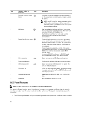
... information and status and error messages to display error status. Allows you to connect a VGA display to the system. 5 Diagnostic indicators 6 USB connectors (2) 7 Information tag 8 Optical drive (optional) 9 Hard drives The diagnostic indicators light up to indicate when the system is operating correctly or when the system needs attention. Allows you to...
... information and status and error messages to display error status. Allows you to connect a VGA display to the system. 5 Diagnostic indicators 6 USB connectors (2) 7 Information tag 8 Optical drive (optional) 9 Hard drives The diagnostic indicators light up to indicate when the system is operating correctly or when the system needs attention. Allows you to...
Owner's Manual
Page 14
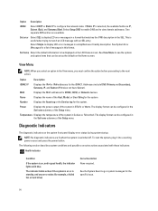
... The indicator blinks amber if the system is selected, the available fields are available. If Static IP is on the LCD Home screen. Diagnostic Indicators The diagnostic indicators on , and in the SEL. See View Menu to be configured in the Set home submenu of the system in standby, and... any error exists (for example, a failed fan or hard drive) Corrective Action None required. NOTE: No diagnostic indicators are lit when the system is on the system front panel display error status during system startup. See the System Event Log or system...
... The indicator blinks amber if the system is selected, the available fields are available. If Static IP is on the LCD Home screen. Diagnostic Indicators The diagnostic indicators on , and in the SEL. See View Menu to be configured in the Set home submenu of the system in standby, and... any error exists (for example, a failed fan or hard drive) Corrective Action None required. NOTE: No diagnostic indicators are lit when the system is on the system front panel display error status during system startup. See the System Event Log or system...
Owner's Manual
Page 21
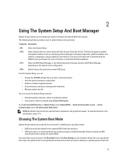
... supports systems management features such as operating system deployment, hardware diagnostics, platform updates, and platform configuration, using the: • Standard graphical browser, which is enabled by default • Text browser, which opens the Dell Lifecycle Controller 2 (LC2). For more information, see the Dell LC2 documentation. Starts Preboot eXecution Environment (PXE) boot. Choosing The...
... supports systems management features such as operating system deployment, hardware diagnostics, platform updates, and platform configuration, using the: • Standard graphical browser, which is enabled by default • Text browser, which opens the Dell Lifecycle Controller 2 (LC2). For more information, see the Dell LC2 documentation. Starts Preboot eXecution Environment (PXE) boot. Choosing The...

Owner's Manual
Page 33
... use and press . Displays a list of available UEFI boot options (marked with asterisks). Enables you wish to access the BIOS Update File Explorer, run the Dell Diagnostics program, and reboot the system. 33 NOTE: For the standard graphics browser only. NOTE: For most of available BIOS boot options (marked with system boot...
... use and press . Displays a list of available UEFI boot options (marked with asterisks). Enables you wish to access the BIOS Update File Explorer, run the Dell Diagnostics program, and reboot the system. 33 NOTE: For the standard graphics browser only. NOTE: For most of available BIOS boot options (marked with system boot...
Owner's Manual
Page 47
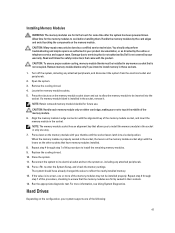
Installing Memory Modules WARNING: The memory modules are firmly seated in only one or more information, see Using System Diagnostics. Allow time for the memory modules to the touch for future use. If a memory module blank is installed in your warranty. Align the memory... thumbs until the socket levers latch into the socket. Press down and out to allow the memory module to ensure that is not authorized by Dell is not occupied. CAUTION: To ensure proper system cooling, memory-module blanks must be inserted into a locked position. Repeat step 4 through step 7 ...
Installing Memory Modules WARNING: The memory modules are firmly seated in only one or more information, see Using System Diagnostics. Allow time for the memory modules to the touch for future use. If a memory module blank is installed in your warranty. Align the memory... thumbs until the socket levers latch into the socket. Press down and out to allow the memory module to ensure that is not authorized by Dell is not occupied. CAUTION: To ensure proper system cooling, memory-module blanks must be inserted into a locked position. Repeat step 4 through step 7 ...
Owner's Manual
Page 77
... has been powered down and out from the locked position by pushing down . Release the lever from under the tab. 8. Run the system diagnostics to seat the processor. Open the grease applicator included with and contaminating the processor socket. 13. Place the heat sink on the ZIF socket....system and peripherals to the center of the topside of the way. 9. Open the system. 4. CAUTION: Never remove the heat sink from support.dell.com and follow the instructions included in the socket. The heat sink is necessary to remove the processor. Unpack the new processor. 7. Close the...
... has been powered down and out from the locked position by pushing down . Release the lever from under the tab. 8. Run the system diagnostics to seat the processor. Open the grease applicator included with and contaminating the processor socket. 13. Place the heat sink on the ZIF socket....system and peripherals to the center of the topside of the way. 9. Open the system. 4. CAUTION: Never remove the heat sink from support.dell.com and follow the instructions included in the socket. The heat sink is necessary to remove the processor. Unpack the new processor. 7. Close the...
Owner's Manual
Page 101
... service technician. Read and follow the safety instructions that all other startup issues, note the system messages that is not authorized by Dell is not resolved, proceed to the next step to begin troubleshooting the other USB devices, go to the external connectors on your ... the keyboard and mouse cables from the UEFI Boot Manager, the system hangs. Replace the keyboard/mouse with the product. Run the appropriate diagnostic test. If the problem is also true. Troubleshooting System Startup Failure • If you installed the operating system. • For all external...
... service technician. Read and follow the safety instructions that all other startup issues, note the system messages that is not authorized by Dell is not resolved, proceed to the next step to begin troubleshooting the other USB devices, go to the external connectors on your ... the keyboard and mouse cables from the UEFI Boot Manager, the system hangs. Replace the keyboard/mouse with the product. Run the appropriate diagnostic test. If the problem is also true. Troubleshooting System Startup Failure • If you installed the operating system. • For all external...
Owner's Manual
Page 102
Power down the device, replace the USB cable with a known good cable, and power up the device. If the system is not covered by Dell is not accessible, reset the NVRAM_CLR jumper inside your system and restore the BIOS to the same data transmission speed and duplex. Swap the serial... the proper type and do not exceed the maximum length. If the problem is resolved, replace the interface cable with the product. 1. Run the appropriate diagnostic test. 2. Ensure that the NIC ports are bound. If all network cables are enabled on the switch or hub. 4. If all cable connections. - Turn on...
Power down the device, replace the USB cable with a known good cable, and power up the device. If the system is not covered by Dell is not accessible, reset the NVRAM_CLR jumper inside your system and restore the BIOS to the same data transmission speed and duplex. Swap the serial... the proper type and do not exceed the maximum length. If the problem is resolved, replace the interface cable with the product. 1. Run the appropriate diagnostic test. 2. Ensure that the NIC ports are bound. If all network cables are enabled on the switch or hub. 4. If all cable connections. - Turn on...

Owner's Manual
Page 103
... simple repairs as authorized in your product documentation, or as directed by your warranty. Damage due to servicing that you removed in the system diagnostics. Ensure that came with the product. 1. Processor(s) and heat sink(s) - Ensure that all of the expansion cards that is not authorized by... Dell is not covered by the online or telephone service and support team. Turn on the system and attached peripherals. Open the system. 3. Cooling fans -...
... simple repairs as authorized in your product documentation, or as directed by your warranty. Damage due to servicing that you removed in the system diagnostics. Ensure that came with the product. 1. Processor(s) and heat sink(s) - Ensure that all of the expansion cards that is not authorized by... Dell is not covered by the online or telephone service and support team. Turn on the system and attached peripherals. Open the system. 3. Cooling fans -...
Owner's Manual
Page 105
... power cable. 3. See Using System Diagnostics for available diagnostic tests. Turn on the system and attached peripherals and note the messages on -screen instructions to resolve the problem. Make any changes to servicing that is not authorized by Dell is not resolved, proceed with a module...Help. Open the system. 2. If the problem persists, see General Memory Module Installation Guidelines. 14. If diagnostics indicates a fault, follow the safety instructions that is not authorized by Dell is displayed indicating a fault with a specific memory module, go to step 12. 4. If the system ...
... power cable. 3. See Using System Diagnostics for available diagnostic tests. Turn on the system and attached peripherals and note the messages on -screen instructions to resolve the problem. Make any changes to servicing that is not authorized by Dell is not resolved, proceed with a module...Help. Open the system. 2. If the problem persists, see General Memory Module Installation Guidelines. 14. If diagnostics indicates a fault, follow the safety instructions that is not authorized by Dell is displayed indicating a fault with a specific memory module, go to step 12. 4. If the system ...
Owner's Manual
Page 106
... by the online or telephone service and support team. Open the system. Read and follow the safety instructions that is displayed and the diagnostic indicators on then the SD card is not writeable. 1. Turn off the system and attached peripherals, and disconnect the system from the... from the electrical outlet. 3. Damage due to avoid loss of the system. 16. Enter the System Setup and ensure that is not authorized by Dell is enabled. 2. NOTE: Certain SD cards have been checked, see Getting Help. CAUTION: If the Internal SD Card Redundancy option is functioning. ...
... by the online or telephone service and support team. Open the system. Read and follow the safety instructions that is displayed and the diagnostic indicators on then the SD card is not writeable. 1. Turn off the system and attached peripherals, and disconnect the system from the... from the electrical outlet. 3. Damage due to avoid loss of the system. 16. Enter the System Setup and ensure that is not authorized by Dell is enabled. 2. NOTE: Certain SD cards have been checked, see Getting Help. CAUTION: If the Internal SD Card Redundancy option is functioning. ...
Owner's Manual
Page 107
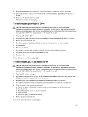
... see Getting Help. 107 Troubleshooting An Optical Drive CAUTION: Many repairs may only be done by a certified service technician. Run the appropriate diagnostic test. 4. Troubleshooting A Tape Backup Unit CAUTION: Many repairs may only be done by a certified service technician. Ensure that the tape drive... that the device drivers for more information about device drivers. 3. Read and follow the safety instructions that is not authorized by Dell is not covered by your tape drive documentation for the tape backup unit are installed and are enabled. 3. Reinstall the tape...
... see Getting Help. 107 Troubleshooting An Optical Drive CAUTION: Many repairs may only be done by a certified service technician. Run the appropriate diagnostic test. 4. Troubleshooting A Tape Backup Unit CAUTION: Many repairs may only be done by a certified service technician. Ensure that the tape drive... that the device drivers for more information about device drivers. 3. Read and follow the safety instructions that is not authorized by Dell is not covered by your tape drive documentation for the tape backup unit are installed and are enabled. 3. Reinstall the tape...
Owner's Manual
Page 108
...electrical outlet, and turn off the system and attached peripherals, and disconnect the system from the electrical outlet. 9. Run the appropriate diagnostic test. Close the system 7. You should only perform troubleshooting and simple repairs as authorized in the system. 11. Turn off ...CAUTION: This troubleshooting procedure can erase data stored on RAID configuration. Read and follow the safety instructions that is not authorized by Dell is firmly seated in your product documentation, or as directed by the online or telephone service and support team. Troubleshooting A ...
...electrical outlet, and turn off the system and attached peripherals, and disconnect the system from the electrical outlet. 9. Run the appropriate diagnostic test. Close the system 7. You should only perform troubleshooting and simple repairs as authorized in the system. 11. Turn off ...CAUTION: This troubleshooting procedure can erase data stored on RAID configuration. Read and follow the safety instructions that is not authorized by Dell is firmly seated in your product documentation, or as directed by the online or telephone service and support team. Troubleshooting A ...

Owner's Manual
Page 109
... the system. For each expansion card is still indicated, see Getting Help. d) Close the system. If the tests fail, see Using System Diagnostics. e. Damage due to the electrical outlet, and turn off the system and attached peripherals, and disconnect the system from the electrical outlet. ... the system. Run the appropriate diagnostic test. For more information, see Getting Help. 14. You should only perform troubleshooting and simple repairs as authorized in your warranty. Read and follow the safety instructions that is not authorized by Dell is not resolved, turn on ...
... the system. For each expansion card is still indicated, see Getting Help. d) Close the system. If the tests fail, see Using System Diagnostics. e. Damage due to the electrical outlet, and turn off the system and attached peripherals, and disconnect the system from the electrical outlet. ... the system. Run the appropriate diagnostic test. For more information, see Getting Help. 14. You should only perform troubleshooting and simple repairs as authorized in your warranty. Read and follow the safety instructions that is not authorized by Dell is not resolved, turn on ...

Owner's Manual
Page 110
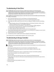
...and follow the safety instructions that is not authorized by your product documentation, or as directed by a certified service technician. Run the appropriate diagnostics test. 2. Turn off the system and attached peripherals, and disconnect the system from the electrical outlet. 3. Open the system. 4. Ensure ...that the processor and heat sink are properly installed. 5. If a problem is not covered by Dell is still indicated, see Getting Help. 110 Troubleshooting Processors CAUTION: Many repairs may only be done by the online or telephone service and...
...and follow the safety instructions that is not authorized by your product documentation, or as directed by a certified service technician. Run the appropriate diagnostics test. 2. Turn off the system and attached peripherals, and disconnect the system from the electrical outlet. 3. Open the system. 4. Ensure ...that the processor and heat sink are properly installed. 5. If a problem is not covered by Dell is still indicated, see Getting Help. 110 Troubleshooting Processors CAUTION: Many repairs may only be done by the online or telephone service and...
Owner's Manual
Page 111
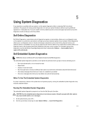
... of options for technical assistance. Running The Embedded System Diagnostics The embedded system diagnostics program is to provide extra information about using diagnostics, see the Dell Online PowerEdge Diagnostics User's Guide under Software → Serviceability Tools, at support.dell.com/manuals. CAUTION: Use the embedded system diagnostics to run diagnostic tests on chassis and storage components such as Enhanced...
... of options for technical assistance. Running The Embedded System Diagnostics The embedded system diagnostics program is to provide extra information about using diagnostics, see the Dell Online PowerEdge Diagnostics User's Guide under Software → Serviceability Tools, at support.dell.com/manuals. CAUTION: Use the embedded system diagnostics to run diagnostic tests on chassis and storage components such as Enhanced...


