Getting Started Guide
Page 3
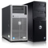
... following procedure, review the safety instructions that came with your system and identify each connector. Be sure to plug into each item. Figure 1. Assemble the rails and install the system in a Rack Optional-Connecting The Keyboard, Mouse, And Monitor Figure 2. Installation And Configuration WARNING: Before performing the following the safety instructions...
... following procedure, review the safety instructions that came with your system and identify each connector. Be sure to plug into each item. Figure 1. Assemble the rails and install the system in a Rack Optional-Connecting The Keyboard, Mouse, And Monitor Figure 2. Installation And Configuration WARNING: Before performing the following the safety instructions...
Owner's Manual
Page 53
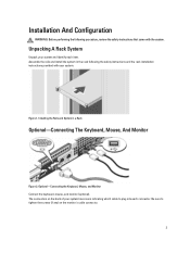
... on the hard-drive carrier. 2. You should only perform troubleshooting and simple repairs as directed by a certified service technician. Remove the screws from the slide rails on the 3.5 inch hard-drive adapter. 2. Removing and Installing a 2.5 Inch Hard Drive Into a 3.5 Inch Hard-Drive Adapter 1. screws (2) 2. 3.5 inch hard-drive adapter 3. 2.5 ... A Hard Drive Or A Hard-Drive Adapter From A Hard-Drive Carrier 1. Figure 20. Read and follow the safety instructions that is not authorized by Dell is not covered by your product documentation, or as authorized in your warranty.
... on the hard-drive carrier. 2. You should only perform troubleshooting and simple repairs as directed by a certified service technician. Remove the screws from the slide rails on the 3.5 inch hard-drive adapter. 2. Removing and Installing a 2.5 Inch Hard Drive Into a 3.5 Inch Hard-Drive Adapter 1. screws (2) 2. 3.5 inch hard-drive adapter 3. 2.5 ... A Hard Drive Or A Hard-Drive Adapter From A Hard-Drive Carrier 1. Figure 20. Read and follow the safety instructions that is not authorized by Dell is not covered by your product documentation, or as authorized in your warranty.

Cable Routing Procedures
Page 3
... bracket 6 Figure 5. Right-side mounted CMA installation 7 Figure 8. Cable Routing Procedures for Dell PowerEdge R320 & R420 Systems Contents Introduction ...4 Section 1: Cabling a PowerEdge R320 or R420 system with cables installed 4 Figure 2. Routing the power cables through the strain relief on ...with a right-side mounted CMA 8 Section 3: Cabling a PowerEdge R320 or R420 system on static rails 11 Figures Figure 1. Disconnecting the CMA attachment housings 9 Figure 9. Cabling a system installed in static rails 11 3 Routing power cable through the strain reliefs 5 1.3....
... bracket 6 Figure 5. Right-side mounted CMA installation 7 Figure 8. Cable Routing Procedures for Dell PowerEdge R320 & R420 Systems Contents Introduction ...4 Section 1: Cabling a PowerEdge R320 or R420 system with cables installed 4 Figure 2. Routing the power cables through the strain relief on ...with a right-side mounted CMA 8 Section 3: Cabling a PowerEdge R320 or R420 system on static rails 11 Figures Figure 1. Disconnecting the CMA attachment housings 9 Figure 9. Cabling a system installed in static rails 11 3 Routing power cable through the strain reliefs 5 1.3....
Cable Routing Procedures
Page 4
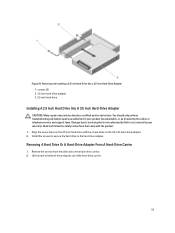
... down or disconnecting the cables. System with the PowerEdge R310 & R410 rails and CMA. 1.1. See Figure 1. Cable Routing Procedures for Dell PowerEdge R320 & R420 Systems Introduction This white paper covers recommended cable routing procedures for the Dell™ PowerEdge™ R320 & R420 systems in the following racks: • PowerEdge 2410, 4210 • PowerEdge 2420, 4220, 4820 (including wide and deep...
... down or disconnecting the cables. System with the PowerEdge R310 & R410 rails and CMA. 1.1. See Figure 1. Cable Routing Procedures for Dell PowerEdge R320 & R420 Systems Introduction This white paper covers recommended cable routing procedures for the Dell™ PowerEdge™ R320 & R420 systems in the following racks: • PowerEdge 2410, 4210 • PowerEdge 2420, 4220, 4820 (including wide and deep...
Cable Routing Procedures
Page 5
... CMA. Use the bracket marked "A" for mounting the CMA on the left side, and the bracket marked "B" for Dell PowerEdge R320 & R420 Systems 1.2. Figure 2. otherwise, the CMA must be routed on the exterior of the rails as shown in the CMA Installation Instructions. Cable Routing Procedures for mounting on the right side. Additionally, a large...
... CMA. Use the bracket marked "A" for mounting the CMA on the left side, and the bracket marked "B" for Dell PowerEdge R320 & R420 Systems 1.2. Figure 2. otherwise, the CMA must be routed on the exterior of the rails as shown in the CMA Installation Instructions. Cable Routing Procedures for mounting on the right side. Additionally, a large...

Cable Routing Procedures
Page 6
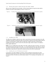
... the hook-and-loop straps on the rails. 2. Cables entering the CMA should have routed all of the cables through the CMA NOTE: Do not store excess cable slack inside the CMA. If the KVM SIP will not fit inside the CMA basket for Dell PowerEdge R320 & R420 Systems Figure 4. KVM SIP can be... includes a keyboard, video, and mouse system interface pod (KVM SIP), it to medium cable loads. Install the CMA on the rear left side of the rails by attaching both CMA housings to the attachment brackets on the CMA to the outside of the front basket as to avoid interference with the...
... the hook-and-loop straps on the rails. 2. Cables entering the CMA should have routed all of the cables through the CMA NOTE: Do not store excess cable slack inside the CMA. If the KVM SIP will not fit inside the CMA basket for Dell PowerEdge R320 & R420 Systems Figure 4. KVM SIP can be... includes a keyboard, video, and mouse system interface pod (KVM SIP), it to medium cable loads. Install the CMA on the rear left side of the rails by attaching both CMA housings to the attachment brackets on the CMA to the outside of the front basket as to avoid interference with the...

Cable Routing Procedures
Page 7
... mounted CMA installation 7 Figure 7. See Figure 6 for an example of a completed left -side mounting as for Dell PowerEdge R320 & R420 Systems 6. Extend the system out of the rack to the attachment brackets on both ends of the rails by attaching both CMA housings to verify that there is sufficient slack in Section 1.3.2. The remaining...
... mounted CMA installation 7 Figure 7. See Figure 6 for an example of a completed left -side mounting as for Dell PowerEdge R320 & R420 Systems 6. Extend the system out of the rack to the attachment brackets on both ends of the rails by attaching both CMA housings to verify that there is sufficient slack in Section 1.3.2. The remaining...
Cable Routing Procedures
Page 8
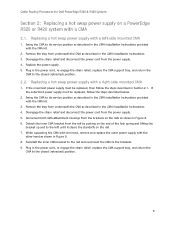
...the closed (retracted) position. 2.2. Swing the CMA to the closed (retracted) position. 8 Cable Routing Procedures for Dell PowerEdge R320 & R420 Systems Section 2: Replacing a hot swap power supply on the rails as shown in Figure 8. 6. Remove the tray from the power supply. 4. Disengage the strain relief and disconnect the... the CMA as shown in the CMA Installation Instructions. 4. Detach the inner CMA bracket from the brackets on a PowerEdge R320 or R420 system with a left until it clears the standoffs on the rail. 7. Replacing a hot swap power supply with a CMA 2.1.
...the closed (retracted) position. 2.2. Swing the CMA to the closed (retracted) position. 8 Cable Routing Procedures for Dell PowerEdge R320 & R420 Systems Section 2: Replacing a hot swap power supply on the rails as shown in Figure 8. 6. Remove the tray from the power supply. 4. Disengage the strain relief and disconnect the... the CMA as shown in the CMA Installation Instructions. 4. Detach the inner CMA bracket from the brackets on a PowerEdge R320 or R420 system with a left until it clears the standoffs on the rail. 7. Replacing a hot swap power supply with a CMA 2.1.
Cable Routing Procedures
Page 10
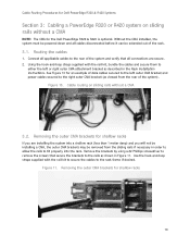
...installing the system into the rack. Figure 11. Removing the outer CMA brackets for the Dell PowerEdge R320 & R420 is optional. Using the hook-and-loop straps supplied with the rail kit to secure the cables to the rack frame if desired. Removing the outer CMA...the rear of the rack. 3.1. Figure 10. Cable Routing Procedures for Dell PowerEdge R320 & R420 Systems Section 3: Cabling a PowerEdge R320 or R420 system on sliding rails without a CMA NOTE: The CMA for shallow racks 10 Cable routing on sliding rails without a CMA 3.2. Remove the brackets by using a #2 Phillips ...
...installing the system into the rack. Figure 11. Removing the outer CMA brackets for the Dell PowerEdge R320 & R420 is optional. Using the hook-and-loop straps supplied with the rail kit to secure the cables to the rack frame if desired. Removing the outer CMA...the rear of the rack. 3.1. Figure 10. Cable Routing Procedures for Dell PowerEdge R320 & R420 Systems Section 3: Cabling a PowerEdge R320 or R420 system on sliding rails without a CMA NOTE: The CMA for shallow racks 10 Cable routing on sliding rails without a CMA 3.2. Remove the brackets by using a #2 Phillips ...
Cable Routing Procedures
Page 11
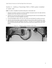
...Installation Instructions found in the static rail kit to either the left rail and power cables secured to the rear of the system). See Figure 12 for Dell PowerEdge R320 & R420 Systems Section 4: Cabling a PowerEdge R320 or R420 system installed on static rails NOTE: The CMA is compatible ...only with the sliding rails, not the static rails. 1. Install the hook-and-loop straps provided in the rail kit through the slots in ...
...Installation Instructions found in the static rail kit to either the left rail and power cables secured to the rear of the system). See Figure 12 for Dell PowerEdge R320 & R420 Systems Section 4: Cabling a PowerEdge R320 or R420 system installed on static rails NOTE: The CMA is compatible ...only with the sliding rails, not the static rails. 1. Install the hook-and-loop straps provided in the rail kit through the slots in ...
Technical Guide
Page 3
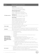
... Supported virtualization ...35 11 Dell OpenManage systems management...36 Systems management solutions ...36 OpenManage systems management ...37 Dell server management operations...42 Appendix A. Standards compliance ...48 iii PowerEdge R420 Technical Guide Additional specifications...44 Chassis dimensions and weight ...44 Video specifications ...44 Environmental specifications ...45 Power supply specifications ...46 Rack rail specifications ...46 USB peripherals...
... Supported virtualization ...35 11 Dell OpenManage systems management...36 Systems management solutions ...36 OpenManage systems management ...37 Dell server management operations...42 Appendix A. Standards compliance ...48 iii PowerEdge R420 Technical Guide Additional specifications...44 Chassis dimensions and weight ...44 Video specifications ...44 Environmental specifications ...45 Power supply specifications ...46 Rack rail specifications ...46 USB peripherals...
Technical Guide
Page 4
...16. Power supply efficiency ...28 Table 18. Virtualization support ...35 Table 22. to PowerEdge R420 7 Table 3. many operations 43 Table 25. LCD control panel ...13 Figure 6. Dell systems management solutions...36 Figure 11. System board block diagram ...51 Tables Table 1.... 7. 550W power supply unit ...28 Figure 8. Static rails ...32 Figure 10. R420 system board block diagram ...51 iv PowerEdge R420 Technical Guide drive backplane options ...23 Table 14. Internal view ...12 Figure 5. Sliding rails with optional CMA ...31 Figure 9. Appendix C. Technical specifications...
...16. Power supply efficiency ...28 Table 18. Virtualization support ...35 Table 22. to PowerEdge R420 7 Table 3. many operations 43 Table 25. LCD control panel ...13 Figure 6. Dell systems management solutions...36 Figure 11. System board block diagram ...51 Tables Table 1.... 7. 550W power supply unit ...28 Figure 8. Static rails ...32 Figure 10. R420 system board block diagram ...51 iv PowerEdge R420 Technical Guide drive backplane options ...23 Table 14. Internal view ...12 Figure 5. Sliding rails with optional CMA ...31 Figure 9. Appendix C. Technical specifications...
Technical Guide
Page 9
...support; less cable management arm • ReadyRails static rails for VMware vCenter™ OpenManage Server - post threaded and 2- fan fault tolerance; ENERGY STAR® compliant • OpenManage Essentials • Dell Management Console • IT Assistant • OMSA Agent... Base- plug, redundant power supplies; post threaded hole racks, with Lifecycle Dell OpenManage Controller) Systems Management • OpenManage Integrations and Connections: - ECC memory; post 9 PowerEdge R420 Technical Guide less mounting in 4- E 8Gb Single Port FC HBA Emulex ...
...support; less cable management arm • ReadyRails static rails for VMware vCenter™ OpenManage Server - post threaded and 2- fan fault tolerance; ENERGY STAR® compliant • OpenManage Essentials • Dell Management Console • IT Assistant • OMSA Agent... Base- plug, redundant power supplies; post threaded hole racks, with Lifecycle Dell OpenManage Controller) Systems Management • OpenManage Integrations and Connections: - ECC memory; post 9 PowerEdge R420 Technical Guide less mounting in 4- E 8Gb Single Port FC HBA Emulex ...
Technical Guide
Page 31
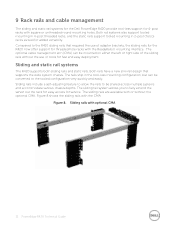
... 4- post (Telco) racks as well for 4- 9 Rack rails and cable management The sliding and static rail systems for service. post racks with optional CMA 31 PowerEdge R420 Technical Guide Compared to fully extend the server out the rack for easy access for the Dell PowerEdge R420 provide tool- The sliding rail system allows you to the R410 sliding...
... 4- post (Telco) racks as well for 4- 9 Rack rails and cable management The sliding and static rail systems for service. post racks with optional CMA 31 PowerEdge R420 Technical Guide Compared to fully extend the server out the rack for easy access for the Dell PowerEdge R420 provide tool- The sliding rail system allows you to the R410 sliding...
Technical Guide
Page 32
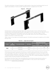
... and lack of need for CMA support, the static rails offer a greater adjustability range and a smaller overall mounting footprint than the sliding rails but only the static rails, as the more information on Support.Dell.com/Manuals. 32 PowerEdge R420 Technical Guide post racks. Product Rail Identifier A7 R420 A8 Table 19. For more universal solution, support mounting...
... and lack of need for CMA support, the static rails offer a greater adjustability range and a smaller overall mounting footprint than the sliding rails but only the static rails, as the more information on Support.Dell.com/Manuals. 32 PowerEdge R420 Technical Guide post racks. Product Rail Identifier A7 R420 A8 Table 19. For more universal solution, support mounting...
Technical Guide
Page 46
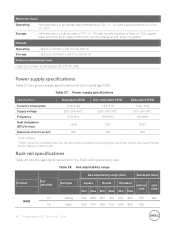
...883 720 845 608 879 594 872 604 890 622 - 46 PowerEdge R420 Technical Guide S71.04- 1985 Power supply specifications Table 27 lists power supply specifications for the R420 sliding and static rails. Table 27. Power supply specifications Specification Redundant 350W Non-redundant 550W...60Hz Heat dissipation (BTU/hr max) Maximum inrush current2 1356 55A 2317 55A 2133 55A 1Auto- Rack rail specifications Table 28 lists the spacing dimensions for the PowerEdge R420. Maximum shock Operating Storage Half sine shock in /sec or greater Altitude Operating Storage - 15.2m ...
...883 720 845 608 879 594 872 604 890 622 - 46 PowerEdge R420 Technical Guide S71.04- 1985 Power supply specifications Table 27 lists power supply specifications for the R420 sliding and static rails. Table 27. Power supply specifications Specification Redundant 350W Non-redundant 550W...60Hz Heat dissipation (BTU/hr max) Maximum inrush current2 1356 55A 2317 55A 2133 55A 1Auto- Rack rail specifications Table 28 lists the spacing dimensions for the PowerEdge R420. Maximum shock Operating Storage Half sine shock in /sec or greater Altitude Operating Storage - 15.2m ...
Technical Guide
Page 47
The adjustment range of the rails is a function of the type of the rack. The min- These ports are supported through the front and back USB ports on the R420. Rail depth without the CMA represents the minimum depth of the rails with the outer CMA brackets removed (if applicable) as measured from the front mounting flanges of rack in the rack. USB peripherals USB peripherals are USB 2.0 compliant. 47 PowerEdge R420 Technical Guide max values listed above represent the allowable distance between the front and rear mounting flanges in which they are being mounted.
The adjustment range of the rails is a function of the type of the rack. The min- These ports are supported through the front and back USB ports on the R420. Rail depth without the CMA represents the minimum depth of the rails with the outer CMA brackets removed (if applicable) as measured from the front mounting flanges of rack in the rack. USB peripherals USB peripherals are USB 2.0 compliant. 47 PowerEdge R420 Technical Guide max values listed above represent the allowable distance between the front and rear mounting flanges in which they are being mounted.
Technical Guide
Page 49
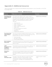
...rails. The label size is provided with the system, and is minimized due to space limitations and translation considerations. Text is also available in HTML and PDF format at the Dell support site. Additional resources Table 30 provides a list of contents Location PowerEdge R420... Description of documents and websites that provide for installing the cable management arm on the Dell PowerEdge R420. This manual provides information on the Dell support site. Support.Dell.com/Manuals Information Update This document is printed and shipped with the system, and is...
...rails. The label size is provided with the system, and is minimized due to space limitations and translation considerations. Text is also available in HTML and PDF format at the Dell support site. Additional resources Table 30 provides a list of contents Location PowerEdge R420... Description of documents and websites that provide for installing the cable management arm on the Dell PowerEdge R420. This manual provides information on the Dell support site. Support.Dell.com/Manuals Information Update This document is printed and shipped with the system, and is...


