User Manual
Page 3
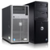
... cards, see "Expansion Cards and Expansion-Card Risers" and "Technical Specifications" in the Owner's Manual at dell.com/ESSA to ensure optimum power utilization. Overview This document provides important information for installing the second processor in Dell PowerEdge R520 and PowerEdge R420 systems. Before You Begin To install a second processor in your system configuration, verify the...
... cards, see "Expansion Cards and Expansion-Card Risers" and "Technical Specifications" in the Owner's Manual at dell.com/ESSA to ensure optimum power utilization. Overview This document provides important information for installing the second processor in Dell PowerEdge R520 and PowerEdge R420 systems. Before You Begin To install a second processor in your system configuration, verify the...
User Manual
Page 4
.... See "Opening the System" in the Owner's Manual. See "Removing the Cooling Shroud" in the Owner's Manual. 4 Remove the cooling shroud. See Figure 1-1. 4 Additonal Processor Installation Read and follow the safety instructions that is not authorized by Dell is held in its socket under the tab. Damage... power prior to servicing that came with the product. 1 Before upgrading your system, download the latest system BIOS version from support.dell.com and follow the instructions included in the compressed download file to install the update on components in your thumb firmly over the...
.... See "Opening the System" in the Owner's Manual. See "Removing the Cooling Shroud" in the Owner's Manual. 4 Remove the cooling shroud. See Figure 1-1. 4 Additonal Processor Installation Read and follow the safety instructions that is not authorized by Dell is held in its socket under the tab. Damage... power prior to servicing that came with the product. 1 Before upgrading your system, download the latest system BIOS version from support.dell.com and follow the instructions included in the compressed download file to install the update on components in your thumb firmly over the...
User Manual
Page 7
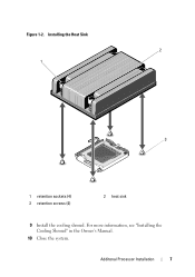
Additonal Processor Installation 7 For more information, see "Installing the Cooling Shroud" in the Owner's Manual. 10 Close the system. Installing the Heat Sink 2 1 3 1 retention sockets (4) 3 retention screws (4) 2 heat sink 9 Install the cooling shroud. Figure 1-2.
Additonal Processor Installation 7 For more information, see "Installing the Cooling Shroud" in the Owner's Manual. 10 Close the system. Installing the Heat Sink 2 1 3 1 retention sockets (4) 3 retention screws (4) 2 heat sink 9 Install the cooling shroud. Figure 1-2.
Getting Started Guide
Page 6
...-redundant AC Power Supply Unit) 4.8 A - 2.4 A (X2) (with 350 W Redundant AC Power Supply Unit) Technical Specifications NOTE: The following information is available online at support.dell.com/manuals. • The rack documentation included with your rack solution describes how to install your system into a rack, if required. • Any media that ships with...
...-redundant AC Power Supply Unit) 4.8 A - 2.4 A (X2) (with 350 W Redundant AC Power Supply Unit) Technical Specifications NOTE: The following information is available online at support.dell.com/manuals. • The rack documentation included with your rack solution describes how to install your system into a rack, if required. • Any media that ships with...
Getting Started Guide
Page 7
....73 kg (36.88 lb) Environmental NOTE: For additional information about environmental measurements for specific system configurations, see support.dell.com/ manuals. NOTE: For information on supported expanded operating temperature range and configurations, see dell.com/environmental_datasheets. Storage Relative humidity -40 °C to 65 °C (-40 °F to 149 °F) with a maximum temperature...
....73 kg (36.88 lb) Environmental NOTE: For additional information about environmental measurements for specific system configurations, see support.dell.com/ manuals. NOTE: For information on supported expanded operating temperature range and configurations, see dell.com/environmental_datasheets. Storage Relative humidity -40 °C to 65 °C (-40 °F to 149 °F) with a maximum temperature...
Owner's Manual
Page 1
Dell PowerEdge R420 Systems Owner's Manual Regulatory Model: E18S Series Regulatory Type: E18S001
Dell PowerEdge R420 Systems Owner's Manual Regulatory Model: E18S Series Regulatory Type: E18S001
Owner's Manual
Page 19
... Other Information You May Need WARNING: See the safety and regulatory information that the power supply is available online at support.dell.com/ manuals. Replace the power supply that has the flashing indicator with a power supply that you must be included within this document,... a Low Output configuration or vice versa, you purchased with your system that provides documentation and tools for updates on support.dell.com/manuals and read the updates first because they can result in other installed power supply. When two identical power supplies receive different ...
... Other Information You May Need WARNING: See the safety and regulatory information that the power supply is available online at support.dell.com/ manuals. Replace the power supply that has the flashing indicator with a power supply that you must be included within this document,... a Low Output configuration or vice versa, you purchased with your system that provides documentation and tools for updates on support.dell.com/manuals and read the updates first because they can result in other installed power supply. When two identical power supplies receive different ...
Owner's Manual
Page 34
..., see the iDRAC7 User's Guide under Software → Systems Management → Dell Remote Access Controllers, at support.dell.com/manuals. In the System Setup Main Menu page, click iDRAC Settings. Embedded System Management The Dell Lifecycle Controller provides advanced embedded systems management throughout the server's lifecycle. You can ...UEFI. The Lifecycle Controller can enable or disable various iDRAC parameters using iDRAC, see the Lifecycle Controller documentation at support.dell.com/manuals. NOTE: Accessing some of features provided by the Lifecycle Controller.
..., see the iDRAC7 User's Guide under Software → Systems Management → Dell Remote Access Controllers, at support.dell.com/manuals. In the System Setup Main Menu page, click iDRAC Settings. Embedded System Management The Dell Lifecycle Controller provides advanced embedded systems management throughout the server's lifecycle. You can ...UEFI. The Lifecycle Controller can enable or disable various iDRAC parameters using iDRAC, see the Lifecycle Controller documentation at support.dell.com/manuals. NOTE: Accessing some of features provided by the Lifecycle Controller.
Owner's Manual
Page 69
For instructions, see the iDRAC7 User's Guide under Software → Systems Management → Dell Remote Access Controllers, at support.dell.com/manuals. Turn off the system, including any attached peripherals, and disconnect the system from the card slot. 69 Open the system. 4. Open the expansion...Slide the expansion-card latch into the iDRAC Ports card connector until the card is a Secure Digital (SD) card that is not authorized by Dell is not covered by its electrical outlet and turn the system on, including any device drivers required for the card as directed by a certified ...
For instructions, see the iDRAC7 User's Guide under Software → Systems Management → Dell Remote Access Controllers, at support.dell.com/manuals. Turn off the system, including any attached peripherals, and disconnect the system from the card slot. 69 Open the system. 4. Open the expansion...Slide the expansion-card latch into the iDRAC Ports card connector until the card is a Secure Digital (SD) card that is not authorized by Dell is not covered by its electrical outlet and turn the system on, including any device drivers required for the card as directed by a certified ...
Owner's Manual
Page 78
... with power supply redundancy. For information about the cable management arm, see the iDRAC7 User's Guide underSoftware → Systems Management → Dell Remote Access Controllers , at a time in the sleep state returns to the system only by a certified service technician. • 550...the straps that significantly reduces the power overhead associated with the product. CAUTION: The system requires one power supply at support.dell.com/ manuals. Power is redundant (1 + 1). When only one power supply is installed, the power supply configuration is switched to maximize ...
... with power supply redundancy. For information about the cable management arm, see the iDRAC7 User's Guide underSoftware → Systems Management → Dell Remote Access Controllers , at a time in the sleep state returns to the system only by a certified service technician. • 550...the straps that significantly reduces the power overhead associated with the product. CAUTION: The system requires one power supply at support.dell.com/ manuals. Power is redundant (1 + 1). When only one power supply is installed, the power supply configuration is switched to maximize ...
Owner's Manual
Page 100
... the system board to the standoffs on , including any attached peripherals. 10. For more information, see iDRAC7 User's Guide, under Software → Systems Management → Dell Remote Access Controllers, at support.dell.com/manuals. 100 4.
... the system board to the standoffs on , including any attached peripherals. 10. For more information, see iDRAC7 User's Guide, under Software → Systems Management → Dell Remote Access Controllers, at support.dell.com/manuals. 100 4.
Owner's Manual
Page 111
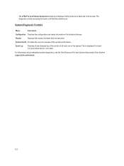
... or save test results • Run thorough tests to introduce additional test options to provide extra information about using diagnostics, see the Dell Online PowerEdge Diagnostics User's Guide under Software → Serviceability Tools, at support.dell.com/manuals. As the system boots, press . 2. Use the up and down arrow keys to run from the...
... or save test results • Run thorough tests to introduce additional test options to provide extra information about using diagnostics, see the Dell Online PowerEdge Diagnostics User's Guide under Software → Serviceability Tools, at support.dell.com/manuals. As the system boots, press . 2. Use the up and down arrow keys to run from the...
Owner's Manual
Page 112
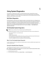
... on all detected devices. Results Displays the results of all tests that are executed. For information about embedded system diagnostics, see the Dell Enhanced Pre-boot System Assessment User Guide at least one event description is displayed, listing all devices detected in the system. The ePSA... on the system. System Health Provides the current overview of all the detected devices. This is displayed if at support.dell.com/manuals. 112 System Diagnostic Controls Menu Description Configuration Displays the configuration and status information of the system performance.
... on all detected devices. Results Displays the results of all tests that are executed. For information about embedded system diagnostics, see the Dell Enhanced Pre-boot System Assessment User Guide at least one event description is displayed, listing all devices detected in the system. The ePSA... on the system. System Health Provides the current overview of all the detected devices. This is displayed if at support.dell.com/manuals. 112 System Diagnostic Controls Menu Description Configuration Displays the configuration and status information of the system performance.
Owner's Manual
Page 118
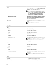
... 2.0-compliant Two optional flash memory card slots with iDRAC Enterprise card NOTE: The card slot is installed on software RAID, see the Dell PowerEdge RAID Controller (PERC) documentation at support.dell.com/manuals. NOTE: DVD devices are data only. Drives Eight hard-drive systems Optical drive Connectors Back NIC Serial USB Video iDRAC7 External...
... 2.0-compliant Two optional flash memory card slots with iDRAC Enterprise card NOTE: The card slot is installed on software RAID, see the Dell PowerEdge RAID Controller (PERC) documentation at support.dell.com/manuals. NOTE: DVD devices are data only. Drives Eight hard-drive systems Optical drive Connectors Back NIC Serial USB Video iDRAC7 External...
Owner's Manual
Page 130
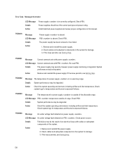
... detected on PSU . Action 1. Check system logs for temperature and thermal component failures. Power supplies should be degraded. Check cables and subsystem components in this manual. Re-seat PSU. Details System performance may be degraded. Check PSU. The power supply has been removed or has failed. 1. If the issue persists, see...
... detected on PSU . Action 1. Check system logs for temperature and thermal component failures. Power supplies should be degraded. Check cables and subsystem components in this manual. Re-seat PSU. Details System performance may be degraded. Check PSU. The power supply has been removed or has failed. 1. If the issue persists, see...
Owner's Manual
Page 131
... cables and subsystem components in the system. PSU0037 Message LCD Message Action Fan failure detected on PSU . Action Install matched power supplies and review this manual for damage. 3. System Performance and power redundancy may be the result of an electrical issue with cables or subsystem components in the system for proper...
... cables and subsystem components in the system. PSU0037 Message LCD Message Action Fan failure detected on PSU . Action Install matched power supplies and review this manual for damage. 3. System Performance and power redundancy may be the result of an electrical issue with cables or subsystem components in the system for proper...
Technical Guide
Page 11
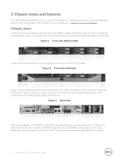
... power supplies, and many other components and features described in this guide. For additional system views and features, see the Dell PowerEdge R420 Systems Owner's Manual on the back panel of the R420 is a 1U, 2- The R420 supports up to components and for airflow for easy access to 12 DIMMs, 2 processors, hot- socket rack server. Figure...
... power supplies, and many other components and features described in this guide. For additional system views and features, see the Dell PowerEdge R420 Systems Owner's Manual on the back panel of the R420 is a 1U, 2- The R420 supports up to components and for airflow for easy access to 12 DIMMs, 2 processors, hot- socket rack server. Figure...
Technical Guide
Page 12
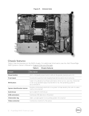
...recording system information Connects a monitor to eight 2.5- Internal view Chassis features Table 4 lists the features on Support.Dell.com/Manuals. Chassis features Feature Description Power button Front bezel NMI button System identification button Hard drives USB connectors Information tag Video... to help identify the unit in a data center environment Up to the server 12 PowerEdge R420 Technical Guide Table 4. For additional information, see the Dell PowerEdge R420 Systems Owner's Manual on the R420 chassis. Figure 4. out label panel for security Used to the server Slide-
...recording system information Connects a monitor to eight 2.5- Internal view Chassis features Table 4 lists the features on Support.Dell.com/Manuals. Chassis features Feature Description Power button Front bezel NMI button System identification button Hard drives USB connectors Information tag Video... to help identify the unit in a data center environment Up to the server 12 PowerEdge R420 Technical Guide Table 4. For additional information, see the Dell PowerEdge R420 Systems Owner's Manual on the R420 chassis. Figure 4. out label panel for security Used to the server Slide-
Technical Guide
Page 13
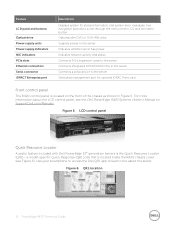
... app to the server Dedicated management port for optional iDRAC Ports card Front control panel The R420 control panel is located on Support.Dell.com/Manuals. two navigation buttons to scroll through the menu on the LCD and one select button Optional slim...information, and system error messages; LCD control panel Quick Resource Locator A useful feature included with Dell PowerEdge 12th generation servers is located inside the R420 chassis cover (see the Dell PowerEdge R420 Systems Owner's Manual on the front of the chassis as shown in Figure 5. Figure 6. specific Quick Response (QR...
... app to the server Dedicated management port for optional iDRAC Ports card Front control panel The R420 control panel is located on Support.Dell.com/Manuals. two navigation buttons to scroll through the menu on the LCD and one select button Optional slim...information, and system error messages; LCD control panel Quick Resource Locator A useful feature included with Dell PowerEdge 12th generation servers is located inside the R420 chassis cover (see the Dell PowerEdge R420 Systems Owner's Manual on the front of the chassis as shown in Figure 5. Figure 6. specific Quick Response (QR...
Technical Guide
Page 14
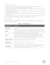
oriented videos and installation wizards • Locate reference materials, including searchable owner's manual content, LCD diagnostics, and an electrical overview • Look up a system password. 14 PowerEdge R420 Technical Guide The Trusted Platform Module (TPM) is used to generate/store keys, protect/authenticate passwords,... is available for China or Russia. A lock on the top cover with technical support and sales teams and provide feedback to Dell These codes provide an easy way to protect un- by link) to get in Table 5 to detect chassis intrusion. Table ...
oriented videos and installation wizards • Locate reference materials, including searchable owner's manual content, LCD diagnostics, and an electrical overview • Look up a system password. 14 PowerEdge R420 Technical Guide The Trusted Platform Module (TPM) is used to generate/store keys, protect/authenticate passwords,... is available for China or Russia. A lock on the top cover with technical support and sales teams and provide feedback to Dell These codes provide an easy way to protect un- by link) to get in Table 5 to detect chassis intrusion. Table ...

