
Glossary
Page 8
...settings on the devices or by an operating system, where each disk. USB devices can be configured for the devices. See also guarding, mirroring, and RAID. system configuration information - TOE - uplink port - Universal Serial Bus. VGA and SVGA are connected in a series,...memory that allows a network manager to remotely monitor and manage workstations. See RAM. TCP/IP - USB - USB memory key - SMP - Super video graphics array. termination - TCP/IP offload engine. A port on each end of space used . SNMP - Uninterruptible power supply. striping - system memory -...
...settings on the devices or by an operating system, where each disk. USB devices can be configured for the devices. See also guarding, mirroring, and RAID. system configuration information - TOE - uplink port - Universal Serial Bus. VGA and SVGA are connected in a series,...memory that allows a network manager to remotely monitor and manage workstations. See RAM. TCP/IP - USB - USB memory key - SMP - Super video graphics array. termination - TCP/IP offload engine. A port on each end of space used . SNMP - Uninterruptible power supply. striping - system memory -...
Hardware Owner's Manual
Page 14
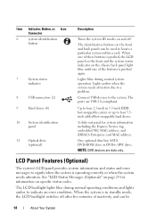
...DVD+/-RW drive. The identification buttons on the front and back panels can be used to locate a particular system within a rack. Connect USB devices to four 3.5inch cabled/hot-swappable hard drives. A slide-out panel for information on page 25 for system information including the Express... Messages (Optional)" on specific status codes. When the system is pushed again. The LCD backlight lights blue during normal system operation. The ports are data only. When one of these buttons is pushed, the LCD panel on the front and the system status indicator on and off...
...DVD+/-RW drive. The identification buttons on the front and back panels can be used to locate a particular system within a rack. Connect USB devices to four 3.5inch cabled/hot-swappable hard drives. A slide-out panel for information on page 25 for system information including the Express... Messages (Optional)" on specific status codes. When the system is pushed again. The LCD backlight lights blue during normal system operation. The ports are data only. When one of these buttons is pushed, the LCD panel on the front and the system status indicator on and off...
Hardware Owner's Manual
Page 19
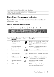
Back-Panel Features and Indicators 12 3 4 5 6 7 8 9 10 11 12 1 2 Gb 1 Gb 2 Item Indicator, Button, or Icon Connector 1 VFlash media slot (optional) 2 iDRAC6 Enterprise port (optional) 3 Serial connector 4 Video connector 5 USB connectors (2) 6 Ethernet connectors (2) 7 PCIe slots (2) Description Connects an external SD memory card for the optional iDRAC6 Enterprise card. Connects a VGA display to the...
Back-Panel Features and Indicators 12 3 4 5 6 7 8 9 10 11 12 1 2 Gb 1 Gb 2 Item Indicator, Button, or Icon Connector 1 VFlash media slot (optional) 2 iDRAC6 Enterprise port (optional) 3 Serial connector 4 Video connector 5 USB connectors (2) 6 Ethernet connectors (2) 7 PCIe slots (2) Description Connects an external SD memory card for the optional iDRAC6 Enterprise card. Connects a VGA display to the...

Hardware Owner's Manual
Page 42
...to take the system mode. Invalid memory configuration. Memory Initialization Warning: Memory size may not work because all user accessible USB ports are disabled in the Internal_Storage slot! than is installed in a will run but with less memory valid configuration. keyboard ...See "Getting Help" on failed. If operating locally, power cycle the system and enter system setup program to enable the USB port(s). out of manufacturing mode. page 169. The system will run but with the specified memory module disabled. The system modules...
...to take the system mode. Invalid memory configuration. Memory Initialization Warning: Memory size may not work because all user accessible USB ports are disabled in the Internal_Storage slot! than is installed in a will run but with less memory valid configuration. keyboard ...See "Getting Help" on failed. If operating locally, power cycle the system and enter system setup program to enable the USB port(s). out of manufacturing mode. page 169. The system will run but with the specified memory module disabled. The system modules...
Hardware Owner's Manual
Page 45
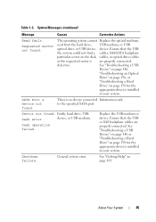
...Actions Read fault. defective. to the specified SATA port. General system error. About Your System 45 The operating system cannot Replace the optical medium, read from the hard drive, USB medium, or USB optical drive, or USB device, device. SATA Port x device not found . Sector not found .... Faulty hard drive, USB Seek error. device, or USB medium. Ensure that the USB the system could not find a cables, SAS/...
...Actions Read fault. defective. to the specified SATA port. General system error. About Your System 45 The operating system cannot Replace the optical medium, read from the hard drive, USB medium, or USB optical drive, or USB device, device. SATA Port x device not found . Sector not found .... Faulty hard drive, USB Seek error. device, or USB medium. Ensure that the USB the system could not find a cables, SAS/...
Hardware Owner's Manual
Page 59
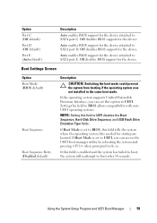
...tells the system where the operating system files needed for startup are located. Auto enables BIOS support for the device attached to SATA port E. Off disables BIOS support for the device. If the operating system supports Unified Extensible Firmware Interface, you can set to UEFI, ... to do so. Off disables BIOS support for the device. Auto enables BIOS support for the device attached to SATA port D. Option Port C (Off default) Port D (Off default) Port E (Auto default) Description Auto enables BIOS support for the device attached to UEFI disables the Boot Sequence, Hard-Disk...
...tells the system where the operating system files needed for startup are located. Auto enables BIOS support for the device attached to SATA port E. Off disables BIOS support for the device. If the operating system supports Unified Extensible Firmware Interface, you can set to UEFI, ... to do so. Off disables BIOS support for the device. Auto enables BIOS support for the device attached to SATA port D. Option Port C (Off default) Port D (Off default) Port E (Auto default) Description Auto enables BIOS support for the device attached to UEFI disables the Boot Sequence, Hard-Disk...

Hardware Owner's Manual
Page 60
...timer. If this field is available if the NIC on board supports iSCSI. Integrated Devices Screen Option User Accessible USB Ports (All Ports On default) Internal USB Port (On default) Embedded NIC1 and NIC2 (Enabled default) Embedded Gb NIC1 (Enabled with iSCSI Boot option is disabled...Enabled default) MAC Address OS Watchdog Timer (Disabled default) Embedded Video Controller (Enabled default) Description Enables or disables the user-accessible USB ports. NOTE: This feature is present. Enables or disables BIOS support for the NIC. NOTE: This field can be accessed through the...
...timer. If this field is available if the NIC on board supports iSCSI. Integrated Devices Screen Option User Accessible USB Ports (All Ports On default) Internal USB Port (On default) Embedded NIC1 and NIC2 (Enabled default) Embedded Gb NIC1 (Enabled with iSCSI Boot option is disabled...Enabled default) MAC Address OS Watchdog Timer (Disabled default) Embedded Video Controller (Enabled default) Description Enables or disables the user-accessible USB ports. NOTE: This feature is present. Enables or disables BIOS support for the NIC. NOTE: This field can be accessed through the...
Hardware Owner's Manual
Page 99
... as authorized in your warranty. For information on creating a bootable file on page 59. Damage due to servicing that is not authorized by Dell is not covered by your product documentation, or as a boot device, security key, or mass storage device. Damage due to its electrical ...enabled in the System Setup program. To boot from the USB memory key, you must be done by the online or telephone service and support team. To use the internal USB connector, the Internal USB Port option must configure the USB memory key with the riser guide posts on the system board...
... as authorized in your warranty. For information on creating a bootable file on page 59. Damage due to servicing that is not authorized by Dell is not covered by your product documentation, or as a boot device, security key, or mass storage device. Damage due to its electrical ...enabled in the System Setup program. To boot from the USB memory key, you must be done by the online or telephone service and support team. To use the internal USB connector, the Internal USB Port option must configure the USB memory key with the riser guide posts on the system board...
Hardware Owner's Manual
Page 146
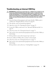
...Restart the system and, if your keyboard is not resolved, proceed to the next step to begin troubleshooting the other USB devices attached to the system. 7 Power down all USB ports are enabled. If your system and restoring the BIOS to video hardware. See "Running the System Diagnostics" on page... side of the system. 3 If the problem is resolved, restart the system, enter the System Setup program, and check if the non functioning USB ports are enabled. 4 Replace the keyboard/mouse with another working keyboard/mouse. 5 If the problem is resolved, replace the faulty keyboard/mouse. 6 ...
...Restart the system and, if your keyboard is not resolved, proceed to the next step to begin troubleshooting the other USB devices attached to the system. 7 Power down all USB ports are enabled. If your system and restoring the BIOS to video hardware. See "Running the System Diagnostics" on page... side of the system. 3 If the problem is resolved, restart the system, enter the System Setup program, and check if the non functioning USB ports are enabled. 4 Replace the keyboard/mouse with another working keyboard/mouse. 5 If the problem is resolved, replace the faulty keyboard/mouse. 6 ...

Hardware Owner's Manual
Page 147
...any peripheral devices connected to the NIC controller. 3 Check the appropriate indicator on each USB device one at a time. 10 If a device causes the same problem, power down the device, replace the USB cable, and power up the device. Remove and reinstall the drivers if applicable. ...Troubleshooting Your System 147 If the problem is resolved, replace the interface cable. 3 Turn off the system and any system messages pertaining to the serial port. 2 Swap the serial ...
...any peripheral devices connected to the NIC controller. 3 Check the appropriate indicator on each USB device one at a time. 10 If a device causes the same problem, power down the device, replace the USB cable, and power up the device. Remove and reinstall the drivers if applicable. ...Troubleshooting Your System 147 If the problem is resolved, replace the interface cable. 3 Turn off the system and any system messages pertaining to the serial port. 2 Swap the serial ...

Hardware Owner's Manual
Page 148
... all network cables are all set to servicing that is not authorized by Dell is not covered by your product documentation, or as directed by a certified service technician. Read... and follow the safety instructions that the NIC ports are bound. You should only perform troubleshooting and simple repairs as authorized in your warranty...exceed the maximum length. • Use another connector on page 75. • Hard drives • USB memory key • NIC hardware key • VFlash media • Expansion card and expansion-card riser...
... all network cables are all set to servicing that is not authorized by Dell is not covered by your product documentation, or as directed by a certified service technician. Read... and follow the safety instructions that the NIC ports are bound. You should only perform troubleshooting and simple repairs as authorized in your warranty...exceed the maximum length. • Use another connector on page 75. • Hard drives • USB memory key • NIC hardware key • VFlash media • Expansion card and expansion-card riser...
Hardware Owner's Manual
Page 155
...by your warranty. Damage due to servicing that is not authorized by Dell is functioning. See "Integrated Devices Screen" on page 78. 4 Locate the USB key and reseat it. If the problem is enabled. See "Internal USB Memory Key" on page 169. Troubleshooting Your System 155 Troubleshooting an ..." on page 79. 10 Turn on the system and attached peripherals and check if the USB key is functioning. 7 If the problem is not resolved, repeat step 2 and step 3. 8 Insert a different USB key that the USB key port is not resolved, see "Getting Help" on page 99. 5 Close the system.
...by your warranty. Damage due to servicing that is not authorized by Dell is functioning. See "Integrated Devices Screen" on page 78. 4 Locate the USB key and reseat it. If the problem is enabled. See "Internal USB Memory Key" on page 169. Troubleshooting Your System 155 Troubleshooting an ..." on page 79. 10 Turn on the system and attached peripherals and check if the USB key is functioning. 7 If the problem is not resolved, repeat step 2 and step 3. 8 Insert a different USB key that the USB key port is not resolved, see "Getting Help" on page 99. 5 Close the system.


