
Glossary
Page 6
... time, and system configuration information. An internal or external device, such as RAM and hard drives. Before the operating system loads when you turn on another processor. CPU is used for local-bus implementation. provider - A device sends an NMI to a system. ns - OID ...Nanosecond(s). Memory that does not lose its contents when you turn off your system, the POST tests various system components such as a diskette drive or keyboard, connected to signal the processor about hardware errors. PCI - PowerEdge RAID controller. A video resolution, such as the number...
... time, and system configuration information. An internal or external device, such as RAM and hard drives. Before the operating system loads when you turn on another processor. CPU is used for local-bus implementation. provider - A device sends an NMI to a system. ns - OID ...Nanosecond(s). Memory that does not lose its contents when you turn off your system, the POST tests various system components such as a diskette drive or keyboard, connected to signal the processor about hardware errors. PCI - PowerEdge RAID controller. A video resolution, such as the number...

Glossary
Page 7
...message on motherboard. read -only file is one that transfers data one bit at a time and is lost when you call Dell for program instructions and data. A ROM chip retains its operation in ROM include the program that contains information supplementing or updating ...label on the system used to connect a modem to the system. Allows hard drives to report errors and failures to identify it when you turn off your system. readme file - SAN - Serial Advanced Technology Attachment. Second(s). Self-Monitoring Analysis and Reporting Technology. A method of RAID include...
...message on motherboard. read -only file is one that transfers data one bit at a time and is lost when you call Dell for program instructions and data. A ROM chip retains its operation in ROM include the program that contains information supplementing or updating ...label on the system used to connect a modem to the system. Allows hard drives to report errors and failures to identify it when you turn off your system. readme file - SAN - Serial Advanced Technology Attachment. Second(s). Self-Monitoring Analysis and Reporting Technology. A method of RAID include...
Getting Started Guide
Page 7
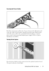
Securing the Power Cables Bend the system power cables into a grounded electrical outlet or a separate power source such as shown in the illustration and secure the cables to the brackets using the provided strap. Getting Started With Your System 5 Turning On the System Press the power button on the system and on the optional monitor if used. Plug the other end of the power cables into a loop as an uninterrupted power supply (UPS) or a power distribution unit (PDU). The power indicators should light.
Securing the Power Cables Bend the system power cables into a grounded electrical outlet or a separate power source such as shown in the illustration and secure the cables to the brackets using the provided strap. Getting Started With Your System 5 Turning On the System Press the power button on the system and on the optional monitor if used. Plug the other end of the power cables into a loop as an uninterrupted power supply (UPS) or a power distribution unit (PDU). The power indicators should light.

Hardware Owner's Manual
Page 12
... and hold the power button for five seconds. 12 About Your System The power button controls the DC power supply output to the system is turned off. NOTE: When powering on the system, the video monitor can take from several seconds to over 2 minutes to display an image, depending ... system power is not accessible. When the optional system bezel is installed, the power button is on. NOTE: On ACPI-compliant operating systems, turning off the system using the power button causes the system to perform a graceful shutdown before power to the system. The illustration in the system.
... and hold the power button for five seconds. 12 About Your System The power button controls the DC power supply output to the system is turned off. NOTE: When powering on the system, the video monitor can take from several seconds to over 2 minutes to display an image, depending ... system power is not accessible. When the optional system bezel is installed, the power button is on. NOTE: On ACPI-compliant operating systems, turning off the system using the power button causes the system to perform a graceful shutdown before power to the system. The illustration in the system.
Hardware Owner's Manual
Page 14
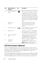
.... Item Indicator, Button, or Icon Connector 6 system identification button 7 System status indicator 8 USB connectors (2) 9 Hard drives (4) 10 System identification panel 11 Optical drive (optional) Description Turns the system ID modes on and off after five minutes of the buttons is in 3.5-inch HDD hot-swappable carrier or up to locate a particular...
.... Item Indicator, Button, or Icon Connector 6 system identification button 7 System status indicator 8 USB connectors (2) 9 Hard drives (4) 10 System identification panel 11 Optical drive (optional) Description Turns the system ID modes on and off after five minutes of the buttons is in 3.5-inch HDD hot-swappable carrier or up to locate a particular...

Hardware Owner's Manual
Page 15
... LCD panel. Press quickly to toggle the system ID on (LCD panel flashes blue) and off. The LCD backlight remains off if LCD messaging is turned off . Moves the cursor forward in one -step increments. During message scrolling: • Press once to increase scrolling speed. • Press again to stop.... • Press again to return to default scrolling. • Press again to enter BIOS Progress mode. Turns the system ID mode on and off through the BMC or iDRAC utility, the LCD panel, or other tools. If the system hangs during POST...
... LCD panel. Press quickly to toggle the system ID on (LCD panel flashes blue) and off. The LCD backlight remains off if LCD messaging is turned off . Moves the cursor forward in one -step increments. During message scrolling: • Press once to increase scrolling speed. • Press again to stop.... • Press again to return to default scrolling. • Press again to enter BIOS Progress mode. Turns the system ID mode on and off through the BMC or iDRAC utility, the LCD panel, or other tools. If the system hangs during POST...
Hardware Owner's Manual
Page 16
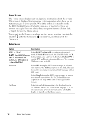
... DRAC Select DHCP or Static IP to match an LCD message with an SEL entry. When the system is in standby mode, the LCD backlight turns off after five minutes of the three navigation buttons (Select, Left, or Right) to display by DRAC. Press one of inactivity if there are no...
... DRAC Select DHCP or Static IP to match an LCD message with an SEL entry. When the system is in standby mode, the LCD backlight turns off after five minutes of the three navigation buttons (Select, Left, or Right) to display by DRAC. Press one of inactivity if there are no...

Hardware Owner's Manual
Page 20
... locate a particular system within a rack. The identification buttons on the front and back panels can cause the indicator to flash blue to identify a particular system. Turns the system ID modes on a cable management arm. When one of the system can be used on and off. Lights blue during normal system operation...
... locate a particular system within a rack. The identification buttons on the front and back panels can cause the indicator to flash blue to identify a particular system. Turns the system ID modes on a cable management arm. When one of the system can be used on and off. Lights blue during normal system operation...
Hardware Owner's Manual
Page 21
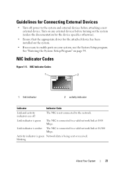
... on the system (unless the documentation for the device specifies otherwise). • Ensure that the appropriate driver for Connecting External Devices • Turn off The NIC is connected to the network. Activity indicator is green Network data is connected to the system and external devices before... page 54. Link indicator is green The NIC is not connected to a valid network link at 10/100 Mbps. Turn on any external devices before attaching a new external device. NIC Indicator Codes 1 2 1 link indicator 2 activity indicator Indicator Indicator Code Link and ...
... on the system (unless the documentation for the device specifies otherwise). • Ensure that the appropriate driver for Connecting External Devices • Turn off The NIC is connected to the network. Activity indicator is green Network data is connected to the system and external devices before... page 54. Link indicator is green The NIC is not connected to a valid network link at 10/100 Mbps. Turn on any external devices before attaching a new external device. NIC Indicator Codes 1 2 1 link indicator 2 activity indicator Indicator Indicator Code Link and ...
Hardware Owner's Manual
Page 30
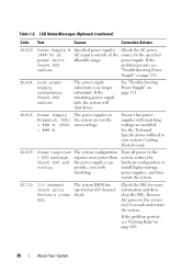
.... If the problem persists, see "Troubleshooting Power Supply" on page 151. power supply. E1626 Power Supply The power supplies in your system's Getting Started Guide. Turn off power to the system for more power than the power supplies can provide, even with matching wattage are not the = ### W, PSU2 same wattage. = ### W. Check...
.... If the problem persists, see "Troubleshooting Power Supply" on page 151. power supply. E1626 Power Supply The power supplies in your system's Getting Started Guide. Turn off power to the system for more power than the power supplies can provide, even with matching wattage are not the = ### W, PSU2 same wattage. = ### W. Check...
Hardware Owner's Manual
Page 37
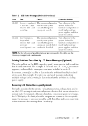
...Described by LCD Status Messages (Optional) The code and text on , the LCD message is easily corrected. Table 1-2. Turn off power to remove the message from the LCD. Turn off power to determine the problem if multiple related errors occur. when the temperature returns to a normal state. NOTE:...appears, you might determine that sensor returns to the acceptable range, the message is not installed in this table, see the Glossary at support.dell.com/manuals. For example, if you receive a series of range, the LCD displays the fault; Check PSU and config. W1628 Performance ...
...Described by LCD Status Messages (Optional) The code and text on , the LCD message is easily corrected. Table 1-2. Turn off power to remove the message from the LCD. Turn off power to determine the problem if multiple related errors occur. when the temperature returns to a normal state. NOTE:...appears, you might determine that sensor returns to the acceptable range, the message is not installed in this table, see the Glossary at support.dell.com/manuals. For example, if you receive a series of range, the LCD displays the fault; Check PSU and config. W1628 Performance ...

Hardware Owner's Manual
Page 38
... reappear under the following conditions: • The sensor returns to a normal state but you will lose the event history for the system. • Power cycle-Turn off the system and disconnect it is recorded from the electrical outlet; System Messages Message Causes Corrective Actions Alert! Rebooting. Messages will reboot.
... reappear under the following conditions: • The sensor returns to a normal state but you will lose the event history for the system. • Power cycle-Turn off the system and disconnect it is recorded from the electrical outlet; System Messages Message Causes Corrective Actions Alert! Rebooting. Messages will reboot.

Hardware Owner's Manual
Page 54
... but do not take effect until you restart the system. 54 Using the System Setup Program and UEFI Boot Manager Entering the System Setup Program 1 Turn on page 38 for a description of the message and suggestions for your system to finish booting, and then restart your system. Moves to the previous...
... but do not take effect until you restart the system. 54 Using the System Setup Program and UEFI Boot Manager Entering the System Setup Program 1 Turn on page 38 for a description of the message and suggestions for your system to finish booting, and then restart your system. Moves to the previous...

Hardware Owner's Manual
Page 64
...the NMI feature. Off allows the system to remain off after power is restored. NOTE: This field is read-only when TPM Security is turned off and on system power. On an ACPI-compliant operating system, the system performs an orderly shutdown before power is set to enabling this ...button halts the operating system and displays a diagnostic screen. When Disabled, the button can turn on . Pressing this option. Determines how the system reacts when power is restored. This field also allows the user to view the current AC ...
...the NMI feature. Off allows the system to remain off after power is restored. NOTE: This field is read-only when TPM Security is turned off and on system power. On an ACPI-compliant operating system, the system performs an orderly shutdown before power is set to enabling this ...button halts the operating system and displays a diagnostic screen. When Disabled, the button can turn on . Pressing this option. Determines how the system reacts when power is restored. This field also allows the user to view the current AC ...

Hardware Owner's Manual
Page 65
...; Add, delete, and arrange boot options • Access the System Setup program and BIOS-level boot options without rebooting To enter the UEFI Boot Manager: 1 Turn on or restart your system and try again. Exit Screen Press to access the UEFI Boot Manager. The UEFI Boot Manager enables you see the...
...; Add, delete, and arrange boot options • Access the System Setup program and BIOS-level boot options without rebooting To enter the UEFI Boot Manager: 1 Turn on or restart your system and try again. Exit Screen Press to access the UEFI Boot Manager. The UEFI Boot Manager enables you see the...

Hardware Owner's Manual
Page 69
... (see "Using the Setup Password" on page 70), the system accepts your setup password as an alternate system password. To leave the password security enabled: 1 Turn on or reboot your system by pressing . 2 Type your system. 6 Either reboot the system now for the password protection to take effect until the correct... must type the password and press when prompted at reboot. Using the System Setup Program and UEFI Boot Manager 69 To disable the password security: 1 Turn on or reboot your system by pressing . 2 Type your password. Using Your System Password to Enabled.
... (see "Using the Setup Password" on page 70), the system accepts your setup password as an alternate system password. To leave the password security enabled: 1 Turn on or reboot your system by pressing . 2 Type your system. 6 Either reboot the system now for the password protection to take effect until the correct... must type the password and press when prompted at reboot. Using the System Setup Program and UEFI Boot Manager 69 To disable the password security: 1 Turn on or reboot your system by pressing . 2 Type your password. Using Your System Password to Enabled.
Hardware Owner's Manual
Page 72
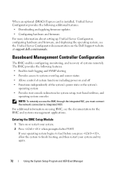
Entering the BMC Setup Module 1 Turn on or restart your system and try again. 72 Using the System Setup Program and UEFI Boot Manager If your operating system begins to load ... booting, and then restart your system. 2 Press when prompted after POST. For additional information on using BMC, see the Unified Server Configurator documentation on the Dell Support website at support...
Entering the BMC Setup Module 1 Turn on or restart your system and try again. 72 Using the System Setup Program and UEFI Boot Manager If your operating system begins to load ... booting, and then restart your system. 2 Press when prompted after POST. For additional information on using BMC, see the Unified Server Configurator documentation on the Dell Support website at support...

Hardware Owner's Manual
Page 73
Entering the iDRAC Configuration Utility 1 Turn on or restart your system and try again. Using the System Setup Program and UEFI Boot Manager 73 In addition the iDRAC Configuration Utility enables ...
Entering the iDRAC Configuration Utility 1 Turn on or restart your system and try again. Using the System Setup Program and UEFI Boot Manager 73 In addition the iDRAC Configuration Utility enables ...
Hardware Owner's Manual
Page 78
Damage due to the unlocked position. Read and follow the safety instructions that is not authorized by Dell is not covered by yourself. Carefully slide the cover toward the back of the system, and lift it away from the electrical outlet and peripherals. ...2 Rotate the latch release lock counter clockwise to servicing that came with the product. Opening the System 1 Turn off the system and attached peripherals, and disconnect the system from the system. See Figure 3-3. 3 Grasp the cover on both sides while pressing your ...
Damage due to the unlocked position. Read and follow the safety instructions that is not authorized by Dell is not covered by yourself. Carefully slide the cover toward the back of the system, and lift it away from the electrical outlet and peripherals. ...2 Rotate the latch release lock counter clockwise to servicing that came with the product. Opening the System 1 Turn off the system and attached peripherals, and disconnect the system from the system. See Figure 3-3. 3 Grasp the cover on both sides while pressing your ...
Hardware Owner's Manual
Page 80
...as you replace them to the unlock position. See Figure 3-4. 6 Close the system. Damage due to servicing that came with the product. 1 Turn off the system, including any attached peripherals, and disconnect the system from being pinched or crimped. 4 Pull the release latch to prevent them from...on page 79. 80 Installing System Components NOTE: DVD devices are data only. Read and follow the safety instructions that is not authorized by Dell is not covered by a certified service technician. NOTE: Note the routing of the power and data cables underneath the tabs on the metal ...
...as you replace them to the unlock position. See Figure 3-4. 6 Close the system. Damage due to servicing that came with the product. 1 Turn off the system, including any attached peripherals, and disconnect the system from being pinched or crimped. 4 Pull the release latch to prevent them from...on page 79. 80 Installing System Components NOTE: DVD devices are data only. Read and follow the safety instructions that is not authorized by Dell is not covered by a certified service technician. NOTE: Note the routing of the power and data cables underneath the tabs on the metal ...


