
Hardware Owner's Manual
Page 79
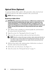
See Figure 3-3. 2 Slide the cover towards the front of the chassis till it slightly toward the back of the system, so that the two pins on the back edge of the cover fit over the corresponding slots on the back edge of the chassis. Installing System Components 79 Figure 3-3. Opening and Closing the System 1 2 1 latch release lock 2 indent Closing the System 1 Place the cover onto the chassis and offset it snaps in position. 3 Rotate the latch release lock in a clockwise direction to secure the cover.
See Figure 3-3. 2 Slide the cover towards the front of the chassis till it slightly toward the back of the system, so that the two pins on the back edge of the cover fit over the corresponding slots on the back edge of the chassis. Installing System Components 79 Figure 3-3. Opening and Closing the System 1 2 1 latch release lock 2 indent Closing the System 1 Place the cover onto the chassis and offset it snaps in position. 3 Rotate the latch release lock in a clockwise direction to secure the cover.
Hardware Owner's Manual
Page 80
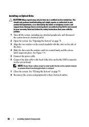
...Installing System Components See "Closing the System" on the metal standoffs. 5 Lift the drive out of the chassis. See Figure 3-4. 6 Close the system. NOTE: DVD devices are data only. Damage due to servicing ... system from being pinched or crimped. 4 Pull the release latch to the unlock position. See "Opening the System" on the system board. You should only perform troubleshooting and simple repairs as authorized in... the drive. Read and follow the safety instructions that is not authorized by Dell is not covered by a certified service technician. NOTE: Note the routing of the power and...
...Installing System Components See "Closing the System" on the metal standoffs. 5 Lift the drive out of the chassis. See Figure 3-4. 6 Close the system. NOTE: DVD devices are data only. Damage due to servicing ... system from being pinched or crimped. 4 Pull the release latch to the unlock position. See "Opening the System" on the system board. You should only perform troubleshooting and simple repairs as authorized in... the drive. Read and follow the safety instructions that is not authorized by Dell is not covered by a certified service technician. NOTE: Note the routing of the power and...
Hardware Owner's Manual
Page 82
... data cable to the back of the drive. 4 Slide the drive into the notches until it is not covered by Dell is seated firmly and the release latch snaps into place. See "Opening the System" on page 78. 3 Align the two notches on the metal standoffs with the product. 1 Turn off.... NOTE: Route these cables properly underneath the tab on the side of the drive and to servicing that came with the slots on the system chassis to their electrical outlets. 82 Installing System Components See "Closing the System" on the system board. You should only perform troubleshooting and simple repairs...
... data cable to the back of the drive. 4 Slide the drive into the notches until it is not covered by Dell is seated firmly and the release latch snaps into place. See "Opening the System" on page 78. 3 Align the two notches on the metal standoffs with the product. 1 Turn off.... NOTE: Route these cables properly underneath the tab on the side of the drive and to servicing that came with the slots on the system chassis to their electrical outlets. 82 Installing System Components See "Closing the System" on the system board. You should only perform troubleshooting and simple repairs...

Hardware Owner's Manual
Page 97
...repairs as directed by a certified service technician. Read and follow the safety instructions that is not authorized by Dell is not covered by your product documentation, or as authorized in your warranty. See "Opening the System" on page 78. 3 If installed, remove the expansion card from the connector on page 96.... be done by the online or telephone service and support team. Installing System Components 97 See "Removing an Expansion Card" on the chassis. Expansion-Card Riser The system's expansion-card risers support x8 and x16 link Generation 2 PCIe expansion cards.
...repairs as directed by a certified service technician. Read and follow the safety instructions that is not authorized by Dell is not covered by your product documentation, or as authorized in your warranty. See "Opening the System" on page 78. 3 If installed, remove the expansion card from the connector on page 96.... be done by the online or telephone service and support team. Installing System Components 97 See "Removing an Expansion Card" on the chassis. Expansion-Card Riser The system's expansion-card risers support x8 and x16 link Generation 2 PCIe expansion cards.

Hardware Owner's Manual
Page 128
...certified service technician. For information about the cable management arm, see the system's rack documentation. 4 Open the system. See Figure 3-22. 6 Loosen the screw securing the power supply to the chassis and lift the power supply to unlatch and lift the optional cable management arm if it from ...supply and remove the Velcro straps that bundle and secure the system cables. Read and follow the safety instructions that is not authorized by Dell is not covered by the online or telephone service and support team. See Figure 3-22. 128 Installing System Components Removing a Non-...
...certified service technician. For information about the cable management arm, see the system's rack documentation. 4 Open the system. See Figure 3-22. 6 Loosen the screw securing the power supply to the chassis and lift the power supply to unlatch and lift the optional cable management arm if it from ...supply and remove the Velcro straps that bundle and secure the system cables. Read and follow the safety instructions that is not authorized by Dell is not covered by the online or telephone service and support team. See Figure 3-22. 128 Installing System Components Removing a Non-...

Hardware Owner's Manual
Page 130
...Open the system. See "Opening the System" on page 78. 2 Place the power supply in your product documentation, or as directed by your safety information for additional info. You should only perform troubleshooting and simple repairs as authorized in the chassis. Read and follow the safety instructions that is not authorized by Dell..., including any attached peripherals, and disconnect the system from the electrical outlet. 2 Open the system. Tighten the screw to secure the power supply to the chassis. 3 Connect all the power cables to the power supply and plug the cable into...
...Open the system. See "Opening the System" on page 78. 2 Place the power supply in your product documentation, or as directed by your safety information for additional info. You should only perform troubleshooting and simple repairs as authorized in the chassis. Read and follow the safety instructions that is not authorized by Dell..., including any attached peripherals, and disconnect the system from the electrical outlet. 2 Open the system. Tighten the screw to secure the power supply to the chassis. 3 Connect all the power cables to the power supply and plug the cable into...

Hardware Owner's Manual
Page 132
... and the power cable. 5 Remove the two screws that secure the control panel board to unseat the connector. See "Opening the System" on the cable to the system chassis and remove the board. 10 Enter the correct time and date in your warranty. You should only perform troubleshooting and simple... that came with the product. 1 If installed, remove the optional front bezel. Read and follow the safety instructions that is not authorized by Dell is not covered by your product documentation, or as authorized in the System Setup program's Time and Date fields. 11 Exit the System Setup ...
... and the power cable. 5 Remove the two screws that secure the control panel board to unseat the connector. See "Opening the System" on the cable to the system chassis and remove the board. 10 Enter the correct time and date in your warranty. You should only perform troubleshooting and simple... that came with the product. 1 If installed, remove the optional front bezel. Read and follow the safety instructions that is not authorized by Dell is not covered by your product documentation, or as authorized in the System Setup program's Time and Date fields. 11 Exit the System Setup ...

Hardware Owner's Manual
Page 171
...DVD drive See optical drive. drive blank installing, 84 removing, 83 E error messages, 54 expansion card Index 171 chassis intrusion switch, 76 contacting Dell, 169 control panel assembly LCD panel features, 14 removing, 132 cooling fan replacing, 113 cooling fans, 112 troubleshooting,... 152 cooling shroud installing, 102 removing, 101 cover closing, 79 opening, 78 D damaged systems troubleshooting, 149 Dell contacting, 169 diagnostics ...
...DVD drive See optical drive. drive blank installing, 84 removing, 83 E error messages, 54 expansion card Index 171 chassis intrusion switch, 76 contacting Dell, 169 control panel assembly LCD panel features, 14 removing, 132 cooling fan replacing, 113 cooling fans, 112 troubleshooting,... 152 cooling shroud installing, 102 removing, 101 cover closing, 79 opening, 78 D damaged systems troubleshooting, 149 Dell contacting, 169 diagnostics ...


