Rack Installation Guide
Page 30
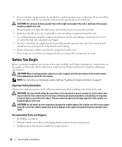
...rack. the slide rails can pinch your system in the rack. CAUTION: When installing multiple systems in a rack, complete all of a Dell rack. Important Safety Information Observe the safety precautions in the following subsections when installing your fingers. • Do not overload the AC ... to prevent injury to yourself and to the rack. Recommended Tools and Supplies • #2 Phillips screwdriver • 3/8-inch wrench or nut driver (if changing bracket to flush-mount configuration) • Masking tape or felt-tip pen to the height and weight of the rack, a...
...rack. the slide rails can pinch your system in the rack. CAUTION: When installing multiple systems in a rack, complete all of a Dell rack. Important Safety Information Observe the safety precautions in the following subsections when installing your fingers. • Do not overload the AC ... to prevent injury to yourself and to the rack. Recommended Tools and Supplies • #2 Phillips screwdriver • 3/8-inch wrench or nut driver (if changing bracket to flush-mount configuration) • Masking tape or felt-tip pen to the height and weight of the rack, a...
Rack Installation Guide
Page 35
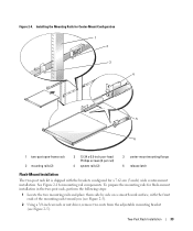
... Installation The two-post rack kit is shipped with the front ends of the mounting rails toward you (see Figure 2-5). 2 Using a 3/8-inch wrench or nut driver, remove two nuts from the adjustable mounting bracket (see Figure 2-5). Two-Post Rack Installation 33 To prepare the mounting rails for flush-mount installation in...
... Installation The two-post rack kit is shipped with the front ends of the mounting rails toward you (see Figure 2-5). 2 Using a 3/8-inch wrench or nut driver, remove two nuts from the adjustable mounting bracket (see Figure 2-5). Two-Post Rack Installation 33 To prepare the mounting rails for flush-mount installation in...
Rack Installation Guide
Page 37
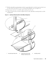
... x 0.5-inch pan-head Phillips screws (see Figure 2-6). 8 Repeat step 6 and step 7 to install the right mounting rail in the rack. 9 Using a 3/8-inch wrench or nut driver, tighten the nuts on the adjustable mounting brackets on both mounting rails. Figure 2-6.
... x 0.5-inch pan-head Phillips screws (see Figure 2-6). 8 Repeat step 6 and step 7 to install the right mounting rail in the rack. 9 Using a 3/8-inch wrench or nut driver, tighten the nuts on the adjustable mounting brackets on both mounting rails. Figure 2-6.
Information Update
Page 1
...screen. c From the Main screen, select CPU Information and press to Disabled. A03 You can download this driver through the update utility or from www.support.dell.com. December 2008 Rev. Microsoft Windows Server 2003 Service Pack Installation Running the Microsoft® Windows® ... If you have installed the Windows Server 2008 (32-bit) operating system using the Dell™ Systems Build and Update Utility, you will cause a system failure. b Press during startup to manually install driver Intel_5100-Chipset-Software-_A02_R196223.exe (version A02 or later). e Press , save your ...
...screen. c From the Main screen, select CPU Information and press to Disabled. A03 You can download this driver through the update utility or from www.support.dell.com. December 2008 Rev. Microsoft Windows Server 2003 Service Pack Installation Running the Microsoft® Windows® ... If you have installed the Windows Server 2008 (32-bit) operating system using the Dell™ Systems Build and Update Utility, you will cause a system failure. b Press during startup to manually install driver Intel_5100-Chipset-Software-_A02_R196223.exe (version A02 or later). e Press , save your ...

Getting Started Guide
Page 7
... displaying programs in the Hardware Owner's Manual. • Enhanced security features, including a system and setup passwords are available through the System Setup program. • Video drivers for system ID and error messaging.
... displaying programs in the Hardware Owner's Manual. • Enhanced security features, including a system and setup passwords are available through the System Setup program. • Video drivers for system ID and error messaging.

Hardware Owner's Manual (PDF)
Page 15
... Provides system ID, status information, and system error messages. Front-Panel Components (continued) Item Component Icon Description 2 NMI button Used to troubleshoot software and device driver errors when using the end of the system can be used to identify a particular system. The LCD lights during normal system operation. About Your System...
... Provides system ID, status information, and system error messages. Front-Panel Components (continued) Item Component Icon Description 2 NMI button Used to troubleshoot software and device driver errors when using the end of the system can be used to identify a particular system. The LCD lights during normal system operation. About Your System...

Hardware Owner's Manual (PDF)
Page 19
... connecting external devices to your system, follow these guidelines: • Most devices must be connected to a specific connector and device drivers must be installed before the device operates properly. (Device drivers are normally included with your operating system software or with the device itself.) See the documentation that accompanied the device for...
... connecting external devices to your system, follow these guidelines: • Most devices must be connected to a specific connector and device drivers must be installed before the device operates properly. (Device drivers are normally included with your operating system software or with the device itself.) See the documentation that accompanied the device for...

Hardware Owner's Manual (PDF)
Page 63
... may need the following items to perform the procedures in this section: • Key to the system keylock • #1 and #2 Phillips screwdrivers • T-10 Torx driver • Wrist grounding strap Installing System Components 63
... may need the following items to perform the procedures in this section: • Key to the system keylock • #1 and #2 Phillips screwdrivers • T-10 Torx driver • Wrist grounding strap Installing System Components 63

Hardware Owner's Manual (PDF)
Page 115
... the hole on page 102. 6 Connect the control panel cable to the system chassis and remove the board. Installing System Components 115 b Using a T10 Torx driver, remove the two screws that secure the control panel board to the control panel board. See Figure 3-22. 8 Remove the display module: a Insert the end...
... the hole on page 102. 6 Connect the control panel cable to the system chassis and remove the board. Installing System Components 115 b Using a T10 Torx driver, remove the two screws that secure the control panel board to the control panel board. See Figure 3-22. 8 Remove the display module: a Insert the end...

Hardware Owner's Manual (PDF)
Page 129
...program and re-enter any custom BIOS settings that were reset. Troubleshooting a NIC Problem • NIC cannot communicate with network. Remove and reinstall the drivers if applicable. If all USB ports enabled. f Repeat step a and step b. Be sure to leave all USB devices are still not functioning, ...21. • If the link indicator does not light, check all cable connections. • If the activity indicator does not light, the network driver files might be damaged or missing. See the NIC's documentation. See "NIC Indicator Codes" on page 69. g Set the NVRAM_CLR jumper to the...
...program and re-enter any custom BIOS settings that were reset. Troubleshooting a NIC Problem • NIC cannot communicate with network. Remove and reinstall the drivers if applicable. If all USB ports enabled. f Repeat step a and step b. Be sure to leave all USB devices are still not functioning, ...21. • If the link indicator does not light, check all cable connections. • If the activity indicator does not light, the network driver files might be damaged or missing. See the NIC's documentation. See "NIC Indicator Codes" on page 69. g Set the NVRAM_CLR jumper to the...

Hardware Owner's Manual (PDF)
Page 130
..., and disconnect the system from the electrical outlet. 2 Open the system. See the NIC's documentation. 4 Enter the System Setup program and confirm that the appropriate drivers are installed and the protocols are enabled. Before performing any of the proper type and do not exceed the maximum length. If the problem persists...
..., and disconnect the system from the electrical outlet. 2 Open the system. See the NIC's documentation. 4 Enter the System Setup program and confirm that the appropriate drivers are installed and the protocols are enabled. Before performing any of the proper type and do not exceed the maximum length. If the problem persists...

Hardware Owner's Manual (PDF)
Page 141
See "Using Dell PowerEdge Diagnostics" on selecting the SCSI ID number and enabling or disabling termination...card. 5 Verify that the tape drive is configured for a unique SCSI ID number and that the SCSI device drivers for instructions on page 151. 7 Turn off the system and attached peripherals, and disconnect the system from the ...8226; Defective tape drive • Defective tape cartridge • Missing or corrupted tape-backup software or tape drive device driver • Defective SCSI controller Action 1 Remove the tape cartridge you were using when the problem occurred, and replace it...
See "Using Dell PowerEdge Diagnostics" on selecting the SCSI ID number and enabling or disabling termination...card. 5 Verify that the tape drive is configured for a unique SCSI ID number and that the SCSI device drivers for instructions on page 151. 7 Turn off the system and attached peripherals, and disconnect the system from the ...8226; Defective tape drive • Defective tape cartridge • Missing or corrupted tape-backup software or tape drive device driver • Defective SCSI controller Action 1 Remove the tape cartridge you were using when the problem occurred, and replace it...

Hardware Owner's Manual (PDF)
Page 142
... cover and access any of the components inside the system. NOTICE: This troubleshooting procedure can destroy data stored on page 143. See "Using Dell PowerEdge Diagnostics" on obtaining technical assistance. See "Opening and Closing the System" on page 68. 9 Reconnect the system to the electrical outlet, .... 10 If the problem is not resolved, see the documentation for the tape drive for information on page 151. Problem • Device driver error. • One or more hard drives not recognized by the system. Before performing any procedure, see your Product Information Guide for...
... cover and access any of the components inside the system. NOTICE: This troubleshooting procedure can destroy data stored on page 143. See "Using Dell PowerEdge Diagnostics" on obtaining technical assistance. See "Opening and Closing the System" on page 68. 9 Reconnect the system to the electrical outlet, .... 10 If the problem is not resolved, see the documentation for the tape drive for information on page 151. Problem • Device driver error. • One or more hard drives not recognized by the system. Before performing any procedure, see your Product Information Guide for...
Hardware Owner's Manual (PDF)
Page 143
... page 73. a Restart the system and press to the operating system. 4 Ensure that the required device drivers for more hard drives not recognized by the system. Troubleshooting a Hot-plug Hard Drive Problem • Device driver error. • One or more information. 5 Verify that the SAS or SATA cables are securely seated in...
... page 73. a Restart the system and press to the operating system. 4 Ensure that the required device drivers for more hard drives not recognized by the system. Troubleshooting a Hot-plug Hard Drive Problem • Device driver error. • One or more information. 5 Verify that the SAS or SATA cables are securely seated in...

Hardware Owner's Manual (PDF)
Page 144
... Guide for your system has a SAS RAID controller, perform the following steps. NOTICE: This troubleshooting procedure can destroy data stored on page 151. See "Using Dell PowerEdge Diagnostics" on the hard drive. See the documentation supplied with a single hard drive, continue to the next step. 4 Turn off your system, reseat the hard... the diagnostics test, proceed as needed through the following step if you proceed, back up all files on page 45. b Ensure that the required device drivers for complete information about the configuration utility.
... Guide for your system has a SAS RAID controller, perform the following steps. NOTICE: This troubleshooting procedure can destroy data stored on page 151. See "Using Dell PowerEdge Diagnostics" on the hard drive. See the documentation supplied with a single hard drive, continue to the next step. 4 Turn off your system, reseat the hard... the diagnostics test, proceed as needed through the following step if you proceed, back up all files on page 45. b Ensure that the required device drivers for complete information about the configuration utility.

Hardware Owner's Manual (PDF)
Page 169
... in -line memory module. Dynamic Host Configuration Protocol. A method of translating Internet domain names, such as www.dell.com, into IP addresses, such as network drivers- DIMM - Additional directories that branch off them. Subdirectories may contain additional directories branching off the root directory are...must load when you to interface correctly with a peripheral. A program that potentially doubles the output. DDR - Some device drivers-such as 143.166.83.200. directory - Dell Remote Access Controller.. ERA allows you start the program for your system.
... in -line memory module. Dynamic Host Configuration Protocol. A method of translating Internet domain names, such as www.dell.com, into IP addresses, such as network drivers- DIMM - Additional directories that branch off them. Subdirectories may contain additional directories branching off the root directory are...must load when you to interface correctly with a peripheral. A program that potentially doubles the output. DDR - Some device drivers-such as 143.166.83.200. directory - Dell Remote Access Controller.. ERA allows you start the program for your system.

Hardware Owner's Manual (PDF)
Page 176
...-based program that automatically supplies power to your system in a series, you to other things, the system.ini file records which video, mouse, and keyboard drivers are connected in the event of wiring used to connect to configure your system's hardware and customize the system's operation by changing jumper or switch...
...-based program that automatically supplies power to your system in a series, you to other things, the system.ini file records which video, mouse, and keyboard drivers are connected in the event of wiring used to connect to configure your system's hardware and customize the system's operation by changing jumper or switch...
Hardware Owner's Manual (PDF)
Page 177
...file - Windows Powered - A Windows operating system designed for example) is dedicated to your monitor must install the appropriate video drivers and your system's RAM. VDC - video adapter - video memory - WH - XML Web services are small reusable applications written in the system...number of colors that provides advanced operating system performance, improved ease of pixels up file for video adapters with the appropriate video drivers and monitor capabilities). Watt(s). VGA and SVGA are installed on NAS systems. For NAS systems, the Windows Powered operating system ...
...file - Windows Powered - A Windows operating system designed for example) is dedicated to your monitor must install the appropriate video drivers and your system's RAM. VDC - video adapter - video memory - WH - XML Web services are small reusable applications written in the system...number of colors that provides advanced operating system performance, improved ease of pixels up file for video adapters with the appropriate video drivers and monitor capabilities). Watt(s). VGA and SVGA are installed on NAS systems. For NAS systems, the Windows Powered operating system ...


