
Glossary
Page 1
... of a program or data file. Celsius. A fast storage area that is located. CA - Certificate authority. AC - ACPI - blade - A - A copy of data or instructions for developing technology standards in the U.S. Common Information Model describes the management information utilized ... pathway between the processor and RAM. The primary organization for quick data retrieval. Advanced Configuration and Power Interface. C - Dell™ Glossary NOTE: For additional information on storage terminology, visit the Storage Networking Industry Association's website at www.snia.org...
... of a program or data file. Celsius. A fast storage area that is located. CA - Certificate authority. AC - ACPI - blade - A - A copy of data or instructions for developing technology standards in the U.S. Common Information Model describes the management information utilized ... pathway between the processor and RAM. The primary organization for quick data retrieval. Advanced Configuration and Power Interface. C - Dell™ Glossary NOTE: For additional information on storage terminology, visit the Storage Networking Industry Association's website at www.snia.org...

Hardware Owner's Manual
Page 3
... During Start-up 13 System Overview 14 System Control Panel Features 16 LCD Module 18 LCD Module Features 19 Using the LCD Module Menus 19 Blade Features 22 Using USB Diskette or USB DVD/CD Drives . . . . 30 Hard-Drive Features 30 Back-Panel Features 33 Power Supply Indicator 35 Fan Module...
... During Start-up 13 System Overview 14 System Control Panel Features 16 LCD Module 18 LCD Module Features 19 Using the LCD Module Menus 19 Blade Features 22 Using USB Diskette or USB DVD/CD Drives . . . . 30 Hard-Drive Features 30 Back-Panel Features 33 Power Supply Indicator 35 Fan Module...

Hardware Owner's Manual
Page 6
... Recommended Tools 145 Removing and Installing a Blade 145 Removing a Blade 145 Installing a Blade 148 Removing and Installing a Blade Blank 148 Removing a Blade Blank 148 Installing a Blade Blank 149 Opening and Closing the Blade 149 Opening the Blade 149 Closing the Blade 159 System Memory 159 System Memory - PowerEdge M910 159 System Memory - PowerEdge M605 185 System Memory - PowerEdge M805 166 System Memory -
... Recommended Tools 145 Removing and Installing a Blade 145 Removing a Blade 145 Installing a Blade 148 Removing and Installing a Blade Blank 148 Removing a Blade Blank 148 Installing a Blade Blank 149 Opening and Closing the Blade 149 Opening the Blade 149 Closing the Blade 159 System Memory 159 System Memory - PowerEdge M910 159 System Memory - PowerEdge M605 185 System Memory - PowerEdge M805 166 System Memory -
Hardware Owner's Manual
Page 8
Removing a Processor 226 Installing a Processor 239 FlexMem Bridge (PowerEdge M910 Only) . . . . 241 HT Bridge Card (PowerEdge M905 Only) . . . . . 242 Blade System Board NVRAM Backup Battery. . . . . 245 Hard Drives 247 Hard Drive Installation Guidelines 247 Installing a Hard Drive 247...Hard-Drive Carrier 249 Installing a Hard Drive in a Drive Carrier . . . . . 249 Video Controller (PowerEdge M905, M805, M605, and M600 Only 251 Hard-Drive Backplane 253 Blade System Board 255 Removing the System Board 255 Installing the System Board 258 Storage Controller Card 259 Removing the Storage...
Removing a Processor 226 Installing a Processor 239 FlexMem Bridge (PowerEdge M910 Only) . . . . 241 HT Bridge Card (PowerEdge M905 Only) . . . . . 242 Blade System Board NVRAM Backup Battery. . . . . 245 Hard Drives 247 Hard Drive Installation Guidelines 247 Installing a Hard Drive 247...Hard-Drive Carrier 249 Installing a Hard Drive in a Drive Carrier . . . . . 249 Video Controller (PowerEdge M905, M805, M605, and M600 Only 251 Hard-Drive Backplane 253 Blade System Board 255 Removing the System Board 255 Installing the System Board 258 Storage Controller Card 259 Removing the Storage...
Hardware Owner's Manual
Page 10
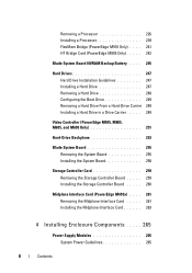
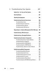
... Troubleshooting Power Supply Modules . . . . . 292 Troubleshooting Fan Modules 293 Troubleshooting the CMC Module 293 Troubleshooting the iKVM Module 295 Troubleshooting a Network Switch Module . . . 296 Troubleshooting Blade Components 297 Troubleshooting Blade Memory 297 Troubleshooting Hard Drives 298 Troubleshooting Expansion Cards 299 Troubleshooting Processors 300 Troubleshooting the...
... Troubleshooting Power Supply Modules . . . . . 292 Troubleshooting Fan Modules 293 Troubleshooting the CMC Module 293 Troubleshooting the iKVM Module 295 Troubleshooting a Network Switch Module . . . 296 Troubleshooting Blade Components 297 Troubleshooting Blade Memory 297 Troubleshooting Hard Drives 298 Troubleshooting Expansion Cards 299 Troubleshooting Processors 300 Troubleshooting the...

Hardware Owner's Manual
Page 11
6 Running System Diagnostics 303 Dell PowerEdge Diagnostics 303 System Diagnostics Features 303 When to Use the System Diagnostics 304 Running the System Diagnostics 304 Running the ...Blade System Board Jumper Settings 309 PowerEdge M910 Jumper Settings 309 PowerEdge M905 Jumper Settings 310 PowerEdge M805 Jumper Settings 311 PowerEdge M710 Jumper Settings 312 PowerEdge M710HD Jumper Settings 313 PowerEdge M610/M610x Jumper Settings. . . . . 314 PowerEdge M600 Jumper Settings 315 System Board Connectors 316 PowerEdge M910 System Board 316 PowerEdge M905 System Board 318 PowerEdge...
6 Running System Diagnostics 303 Dell PowerEdge Diagnostics 303 System Diagnostics Features 303 When to Use the System Diagnostics 304 Running the System Diagnostics 304 Running the ...Blade System Board Jumper Settings 309 PowerEdge M910 Jumper Settings 309 PowerEdge M905 Jumper Settings 310 PowerEdge M805 Jumper Settings 311 PowerEdge M710 Jumper Settings 312 PowerEdge M710HD Jumper Settings 313 PowerEdge M610/M610x Jumper Settings. . . . . 314 PowerEdge M600 Jumper Settings 315 System Board Connectors 316 PowerEdge M910 System Board 316 PowerEdge M905 System Board 318 PowerEdge...
Hardware Owner's Manual
Page 14
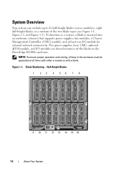
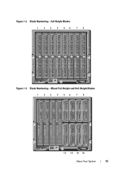
... Controller (CMC) module, and at all times with either a module or with a blank. Blade Numbering - The power supplies, fans, CMC, optional iKVM module, and I /O module for external network connectivity. Figure 1-1. Half-Height Blades 1 2 3 4 56 7 8 9 10 11 12 13 14 15 16 14 About Your...blades (server modules), eight full-height blades, or a mixture of the blades in the enclosure must be populated at least one I /O modules are shared resources of the two blade types (see Figure 1-1, Figure 1-2, and Figure 1-3). NOTE: To ensure proper operation and cooling, all bays in the PowerEdge...
... Controller (CMC) module, and at all times with either a module or with a blank. Blade Numbering - The power supplies, fans, CMC, optional iKVM module, and I /O module for external network connectivity. Figure 1-1. Half-Height Blades 1 2 3 4 56 7 8 9 10 11 12 13 14 15 16 14 About Your...blades (server modules), eight full-height blades, or a mixture of the blades in the enclosure must be populated at least one I /O modules are shared resources of the two blade types (see Figure 1-1, Figure 1-2, and Figure 1-3). NOTE: To ensure proper operation and cooling, all bays in the PowerEdge...
Hardware Owner's Manual
Page 15
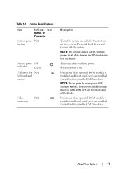
Blade Numbering - Mixed Full-Height and Half-Height Blades 1 2 3 4 56 7 8 13 14 15 16 About Your System 15 Full Height Blades 1 2 3 4 56 7 8 Figure 1-3. Blade Numbering - Figure 1-2.
Blade Numbering - Mixed Full-Height and Half-Height Blades 1 2 3 4 56 7 8 13 14 15 16 About Your System 15 Full Height Blades 1 2 3 4 56 7 8 Figure 1-3. Blade Numbering - Figure 1-2.
Hardware Owner's Manual
Page 17
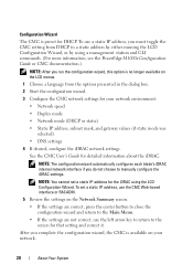
... I/O modules in the CMC interface. Only connect USB storage devices to turn on and off the system. Press to all of the blade. System power is installed and front panel ports are enabled (default setting) in the enclosure. Functional if an optional iKVM module is installed and front ...
... I/O modules in the CMC interface. Only connect USB storage devices to turn on and off the system. Press to all of the blade. System power is installed and front panel ports are enabled (default setting) in the enclosure. Functional if an optional iKVM module is installed and front ...
Hardware Owner's Manual
Page 18
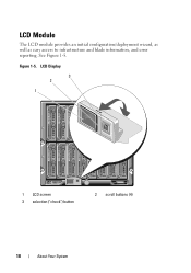
Figure 1-5. See Figure 1-5. LCD Module The LCD module provides an initial configuration/deployment wizard, as well as easy access to infrastructure and blade information, and error reporting. LCD Display 3 2 1 1 LCD screen 3 selection ("check") button 2 scroll buttons (4) 18 About Your System
Figure 1-5. See Figure 1-5. LCD Module The LCD module provides an initial configuration/deployment wizard, as well as easy access to infrastructure and blade information, and error reporting. LCD Display 3 2 1 1 LCD screen 3 selection ("check") button 2 scroll buttons (4) 18 About Your System

Hardware Owner's Manual
Page 19
... allows you to configure the CMC module's network settings during initial system set up. • Menus to configure the iDRAC in each blade. • Status information screens for each blade. • Status information screens for the modules installed in the back of the enclosure, including the IO modules, fans, CMC, iKVM, and...
... allows you to configure the CMC module's network settings during initial system set up. • Menus to configure the iDRAC in each blade. • Status information screens for each blade. • Status information screens for the modules installed in the back of the enclosure, including the IO modules, fans, CMC, iKVM, and...
Hardware Owner's Manual
Page 20
... address by either running the LCD Configuration Wizard, or by using a management station and CLI commands. (For more information, see the PowerEdge M1000e Configuration Guide or CMC documentation.) NOTE: After you must toggle the CMC setting from the options presented in the dialog box. 2... setting and correct it. After you do not choose to manually configure the iDRAC settings. NOTE: The configuration wizard automatically configures each blade's iDRAC internal network interface if you complete the configuration wizard, the CMC is no longer available on your network environment: •...
... address by either running the LCD Configuration Wizard, or by using a management station and CLI commands. (For more information, see the PowerEdge M1000e Configuration Guide or CMC documentation.) NOTE: After you must toggle the CMC setting from the options presented in the dialog box. 2... setting and correct it. After you do not choose to manually configure the iDRAC settings. NOTE: The configuration wizard automatically configures each blade's iDRAC internal network interface if you complete the configuration wizard, the CMC is no longer available on your network environment: •...

Hardware Owner's Manual
Page 21
... Menu From the Server Menu dialog box, you can change the default language and start-up screen for the CMC, the iDRAC in each blade, and other components in the enclosure using this condition is indicated by an amber rectangle. - About Your System 21 Main Menu The Main ... dialog box, you can highlight each component in the enclosure and view its status. • A blade that is powered off or booting is selected, a dialog box displays the current status of the blade and any error conditions, and power consumption statistics. • The Network Summary screen lists the IP...
... Menu From the Server Menu dialog box, you can change the default language and start-up screen for the CMC, the iDRAC in each blade, and other components in the enclosure using this condition is indicated by an amber rectangle. - About Your System 21 Main Menu The Main ... dialog box, you can highlight each component in the enclosure and view its status. • A blade that is powered off or booting is selected, a dialog box displays the current status of the blade and any error conditions, and power consumption statistics. • The Network Summary screen lists the IP...
Hardware Owner's Manual
Page 22
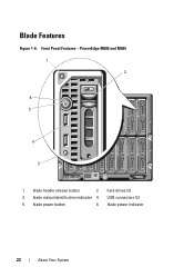
Front Panel Features - Blade Features Figure 1-6. PowerEdge M600 and M605 1 2 6 5 4 3 1 blade handle release button 2 hard drives (2) 3 blade status/identification indicator 4 USB connectors (2) 5 blade power button 6 blade power indicator 22 About Your System
Front Panel Features - Blade Features Figure 1-6. PowerEdge M600 and M605 1 2 6 5 4 3 1 blade handle release button 2 hard drives (2) 3 blade status/identification indicator 4 USB connectors (2) 5 blade power button 6 blade power indicator 22 About Your System
Hardware Owner's Manual
Page 23
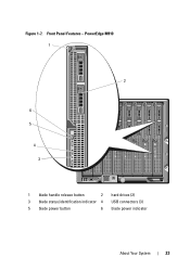
PowerEdge M910 1 2 6 5 4 3 1 blade handle release button 2 hard drives (2) 3 blade status/identification indicator 4 USB connectors (3) 5 blade power button 6 blade power indicator About Your System 23 Front Panel Features - Figure 1-7.
PowerEdge M910 1 2 6 5 4 3 1 blade handle release button 2 hard drives (2) 3 blade status/identification indicator 4 USB connectors (3) 5 blade power button 6 blade power indicator About Your System 23 Front Panel Features - Figure 1-7.
Hardware Owner's Manual
Page 24
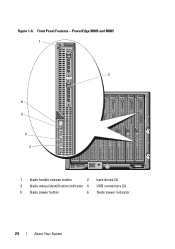
Figure 1-8. Front Panel Features - PowerEdge M905 and M805 1 2 6 5 4 3 1 blade handle release button 2 hard drives (2) 3 blade status/identification indicator 4 USB connectors (3) 5 blade power button 6 blade power indicator 24 About Your System
Figure 1-8. Front Panel Features - PowerEdge M905 and M805 1 2 6 5 4 3 1 blade handle release button 2 hard drives (2) 3 blade status/identification indicator 4 USB connectors (3) 5 blade power button 6 blade power indicator 24 About Your System
Hardware Owner's Manual
Page 25
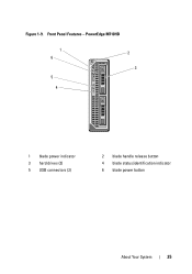
PowerEdge M710HD 1 6 5 4 2 3 1 blade power indicator 3 hard drives (2) 5 USB connectors (2) 2 blade handle release button 4 blade status/identification indicator 6 blade power button About Your System 25 Figure 1-9. Front Panel Features -
PowerEdge M710HD 1 6 5 4 2 3 1 blade power indicator 3 hard drives (2) 5 USB connectors (2) 2 blade handle release button 4 blade status/identification indicator 6 blade power button About Your System 25 Figure 1-9. Front Panel Features -
Hardware Owner's Manual
Page 26
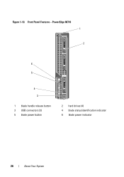
Front Panel Features - PowerEdge M710 1 2 6 5 4 3 1 blade handle release button 3 USB connectors (3) 5 blade power button 2 hard drives (4) 4 blade status/identification indicator 6 blade power indicator 26 About Your System Figure 1-10.
Front Panel Features - PowerEdge M710 1 2 6 5 4 3 1 blade handle release button 3 USB connectors (3) 5 blade power button 2 hard drives (4) 4 blade status/identification indicator 6 blade power indicator 26 About Your System Figure 1-10.
Hardware Owner's Manual
Page 27
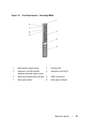
Figure 1-11. PowerEdge M610x 1 8 7 6 2 5 3 4 1 blade handle release button 2 hard drive (2) 3 expansion-card filler-bracket 4 expansion-card slot (2) retention latch with captive screw 5 blade status/identification indicator 6 USB connector (2) 7 blade power button 8 blade power indicator About Your System 27 Front Panel Features -
Figure 1-11. PowerEdge M610x 1 8 7 6 2 5 3 4 1 blade handle release button 2 hard drive (2) 3 expansion-card filler-bracket 4 expansion-card slot (2) retention latch with captive screw 5 blade status/identification indicator 6 USB connector (2) 7 blade power button 8 blade power indicator About Your System 27 Front Panel Features -
Hardware Owner's Manual
Page 28
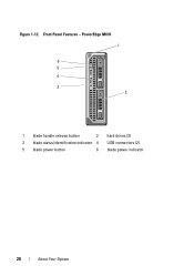
Front Panel Features - PowerEdge M610 1 6 5 4 3 2 1 blade handle release button 2 hard drives (2) 3 blade status/identification indicator 4 USB connectors (2) 5 blade power button 6 blade power indicator 28 About Your System Figure 1-12.
Front Panel Features - PowerEdge M610 1 6 5 4 3 2 1 blade handle release button 2 hard drives (2) 3 blade status/identification indicator 4 USB connectors (2) 5 blade power button 6 blade power indicator 28 About Your System Figure 1-12.


