
Glossary
Page 3
... input device, and a monitor is powered on the system board or riser board for connection of electronic chip that uses the Internet SCSI protocol. F - Gigabit(s); 1024 megabits or 1,073,741,824 bits. Hertz. A connector on and running. expansion-card connector - Front-side bus. A remote access controller that can optionally use a FAT file system structure. Internet Protocol version 6. 3 A type of processors with networked storage devices. A standard interface between the processor and the main memory (RAM). The Microsoft® Windows® operating...
... input device, and a monitor is powered on the system board or riser board for connection of electronic chip that uses the Internet SCSI protocol. F - Gigabit(s); 1024 megabits or 1,073,741,824 bits. Hertz. A connector on and running. expansion-card connector - Front-side bus. A remote access controller that can optionally use a FAT file system structure. Internet Protocol version 6. 3 A type of processors with networked storage devices. A standard interface between the processor and the main memory (RAM). The Microsoft® Windows® operating...
Hardware Owner's Manual
Page 119
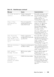
... UEFI Boot Manager" on page 198. BIOS Update Attempt Failed. About Your System 119 ROM bad checksum = address Expansion card improperly Ensure that the expansion installed or faulty. BIOS remote update failed. Run the System Setup program and review the current settings. Faulty or improperly installed mezzanine card. faulty blade board. If the problem persists, see "Getting Help" on page 337. PCIe Training Error: Expected Link Width is x', Actual Link Width is installed properly. Invalid configuration information please run SETUP program CMOS checksum failure...
... UEFI Boot Manager" on page 198. BIOS Update Attempt Failed. About Your System 119 ROM bad checksum = address Expansion card improperly Ensure that the expansion installed or faulty. BIOS remote update failed. Run the System Setup program and review the current settings. Faulty or improperly installed mezzanine card. faulty blade board. If the problem persists, see "Getting Help" on page 337. PCIe Training Error: Expected Link Width is x', Actual Link Width is installed properly. Invalid configuration information please run SETUP program CMOS checksum failure...
Hardware Owner's Manual
Page 127
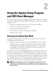
... 32-bit operating systems do not support UEFI and can : • Change the NVRAM settings after you add or remove hardware • View the system hardware configuration • Enable or disable integrated devices • Set performance and power management thresholds • Manage system security Choosing the System Boot Mode The System Setup program also enables you to specify the boot mode for more information on this interface. Using the System Setup Program and UEFI Boot Manager You select the boot mode in the specified boot mode...
... 32-bit operating systems do not support UEFI and can : • Change the NVRAM settings after you add or remove hardware • View the system hardware configuration • Enable or disable integrated devices • Set performance and power management thresholds • Manage system security Choosing the System Boot Mode The System Setup program also enables you to specify the boot mode for more information on this interface. Using the System Setup Program and UEFI Boot Manager You select the boot mode in the specified boot mode...

Hardware Owner's Manual
Page 131
... used by software that the modules support multiple voltages. Using the System Setup Program and UEFI Boot Manager 131 Displays the bus speed of the processors. Options are Spare Mode and Disabled. Memory Operating If set to a higher value (1.5 V) provided that supports Virtualization Technology. If Enabled, memory interleaving is employed. Redundant Memory (PowerEdge M910, M905, M805, and M605) If a valid memory configuration is installed, you can enable memory mirroring or spare memory. Processor Settings Screen Option 64-bit Core Speed Bus Speed Logical Processor (Enabled...
... used by software that the modules support multiple voltages. Using the System Setup Program and UEFI Boot Manager 131 Displays the bus speed of the processors. Options are Spare Mode and Disabled. Memory Operating If set to a higher value (1.5 V) provided that supports Virtualization Technology. If Enabled, memory interleaving is employed. Redundant Memory (PowerEdge M910, M905, M805, and M605) If a valid memory configuration is installed, you can enable memory mirroring or spare memory. Processor Settings Screen Option 64-bit Core Speed Bus Speed Logical Processor (Enabled...

Hardware Owner's Manual
Page 132
... Line Prefetch (Enabled default) Hardware Prefetcher (Enabled default) DCU Streamer Prefetcher (Enabled default) Data Reuse Execute Disable (Enabled default) Number of the processor(s). Off disables the controller. Off disables BIOS support for the device. 132 Using the System Setup Program and UEFI Boot Manager Enables or disables data reuse in each processor. A submenu displays the core speed, the amount of cache memory, and the number of cores of Cores per Processor (All default) Intel QPI Bandwidth Priority Turbo Mode C States (Enabled default) Processor X FamilyModel-Stepping...
... Line Prefetch (Enabled default) Hardware Prefetcher (Enabled default) DCU Streamer Prefetcher (Enabled default) Data Reuse Execute Disable (Enabled default) Number of the processor(s). Off disables the controller. Off disables BIOS support for the device. 132 Using the System Setup Program and UEFI Boot Manager Enables or disables data reuse in each processor. A submenu displays the core speed, the amount of cache memory, and the number of cores of Cores per Processor (All default) Intel QPI Bandwidth Priority Turbo Mode C States (Enabled default) Processor X FamilyModel-Stepping...
Hardware Owner's Manual
Page 134
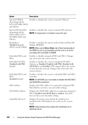
...) Enables or disables the mirror mode for a particular integrated NIC. Changes take effect after the system reboots. MAC Address Displays the MAC address for Internal Dual SD Module (IDSDM). Capability Detected Displays the features provided by the hardware key installed in IDSDM. Changes NICn take effect after the system reboots. PXE support allows the system to Mirror Mode, the vFlash functionality of an additional driver. 134 Using the System Setup Program and UEFI Boot Manager iSCSI MAC Address Displays...
...) Enables or disables the mirror mode for a particular integrated NIC. Changes take effect after the system reboots. MAC Address Displays the MAC address for Internal Dual SD Module (IDSDM). Capability Detected Displays the features provided by the hardware key installed in IDSDM. Changes NICn take effect after the system reboots. PXE support allows the system to Mirror Mode, the vFlash functionality of an additional driver. 134 Using the System Setup Program and UEFI Boot Manager iSCSI MAC Address Displays...

Hardware Owner's Manual
Page 140
..., you to Disabled, and you cannot change the system password. Assigning a System Password Before assigning a system password, enter the System Setup program and check the System Password option. Disabling the password jumper on the system board sets System Password to run utilities such as system diagnostics. For more information, see the Unified Server Configurator User's Guide. Accesses the BIOS-level boot options list without rebooting. If Password Status is assigned, the system prompts for the data on your system...
..., you to Disabled, and you cannot change the system password. Assigning a System Password Before assigning a system password, enter the System Setup program and check the System Password option. Disabling the password jumper on the system board sets System Password to run utilities such as system diagnostics. For more information, see the Unified Server Configurator User's Guide. Accesses the BIOS-level boot options list without rebooting. If Password Status is assigned, the system prompts for the data on your system...
Hardware Owner's Manual
Page 290
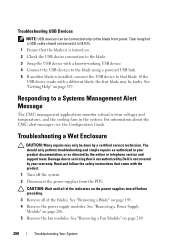
.... 1 Turn off before preceding. 3 Remove all of a USB cable should only perform troubleshooting and simple repairs as directed by the online or telephone service and support team. You should not exceed 3 m (9.8 ft). 1 Ensure that the blade(s) is turned on. 2 Check the USB device connection to the blade. 3 Swap the USB device with a known-working USB device. 4 Connect the USB devices to the blade using a powered USB hub. 5 If another blade is installed, connect the USB device to servicing...
.... 1 Turn off before preceding. 3 Remove all of a USB cable should only perform troubleshooting and simple repairs as directed by the online or telephone service and support team. You should not exceed 3 m (9.8 ft). 1 Ensure that the blade(s) is turned on. 2 Check the USB device connection to the blade. 3 Swap the USB device with a known-working USB device. 4 Connect the USB devices to the blade using a powered USB hub. 5 If another blade is installed, connect the USB device to servicing...

Dell M8428-k Hardware Reference Manual
Page 13
The 16 internal ports connect to 8 Gbps. The switch module contains three (3) temperature sensors. While the sensors will report the temperature of the bays labeled B1, B2, C1, or C2. The FC ports support link speeds up to the server utilizing 10GBase-KR (KR) technology. Management for the converged network switch can function in a Dell PowerEdge M1000e Blade Server Enclosure. Chapter Introducing the Dell M8428-k 1 In this chapter •Dell M8428-k overview...
The 16 internal ports connect to 8 Gbps. The switch module contains three (3) temperature sensors. While the sensors will report the temperature of the bays labeled B1, B2, C1, or C2. The FC ports support link speeds up to the server utilizing 10GBase-KR (KR) technology. Management for the converged network switch can function in a Dell PowerEdge M1000e Blade Server Enclosure. Chapter Introducing the Dell M8428-k 1 In this chapter •Dell M8428-k overview...

Dell PowerConnect M8024-k Release Notes
Page 23
... user always gets Read-Only access if using TACACS as TACACS. The software recognizes if the group name is well under 100 ms for large configurations Trunk mode VLANs transmit tagged frames only User Impact DUT may draw more power than negotiated, but power loss due to 500 ms for file download failures. If a user enters an invalid interface, a generic error message is issued. System Firmware Version...
... user always gets Read-Only access if using TACACS as TACACS. The software recognizes if the group name is well under 100 ms for large configurations Trunk mode VLANs transmit tagged frames only User Impact DUT may draw more power than negotiated, but power loss due to 500 ms for file download failures. If a user enters an invalid interface, a generic error message is issued. System Firmware Version...
Dell PowerConnect M8024-k User's Configuration Guide
Page 785
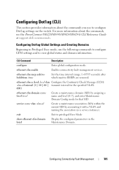
... support.dell.com/manuals. ethernet cfm enable Enables connectivity fault management services. CLI Command Description configure Enter global configuration mode. ethernet cfm cc level level vlan Configure the Continuity Check Message (CCM) vlan-id interval {1 | 10 | 60 | transmit interval for that MD. Configuring Dot1ag Global Settings and Creating Domains Beginning in the Maintenance Domain. exit Exit to view global status and domain information. For more information about the commands you use the following commands...
... support.dell.com/manuals. ethernet cfm enable Enables connectivity fault management services. CLI Command Description configure Enter global configuration mode. ethernet cfm cc level level vlan Configure the Continuity Check Message (CCM) vlan-id interval {1 | 10 | 60 | transmit interval for that MD. Configuring Dot1ag Global Settings and Creating Domains Beginning in the Maintenance Domain. exit Exit to view global status and domain information. For more information about the commands you use the following commands...

Dell PowerConnect M6220/M6348/M8024/M8024-k CLI Reference Guide
Page 186
... set to the highest available access for example, engine ID, view, and so on the switch: • Establishes the initial privileged user account with an IP address of a newly installed switch so that it is configured, the default access level is disabled until the user returns to configure security access for SNMPv3 (for the SNMP management interface. By default the switch is discouraged. The wizard sets up the default gateway IP address. 186 Using...
... set to the highest available access for example, engine ID, view, and so on the switch: • Establishes the initial privileged user account with an IP address of a newly installed switch so that it is configured, the default access level is disabled until the user returns to configure security access for SNMPv3 (for the SNMP management interface. By default the switch is discouraged. The wizard sets up the default gateway IP address. 186 Using...
Brocade 4424 Blade Server SAN I/O Module Hardware Reference
Page 8
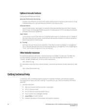
... faults based on thresholds set for a variety of SAN fabrics while simplifying ISL management. Other industry resources For additional resource information, visit the Technical Committee T11 Web site. General Information Technical Support contract number, if applicable SAN I/O Module model SAN I/O Module operating system version Error numbers and messages received supportSave command output Detailed description of the problem and specific questions viii 4424 Blade Server SAN I /O Module support supplier for Fibre Channel, storage management...
... faults based on thresholds set for a variety of SAN fabrics while simplifying ISL management. Other industry resources For additional resource information, visit the Technical Committee T11 Web site. General Information Technical Support contract number, if applicable SAN I/O Module model SAN I/O Module operating system version Error numbers and messages received supportSave command output Detailed description of the problem and specific questions viii 4424 Blade Server SAN I /O Module support supplier for Fibre Channel, storage management...

Dell PowerEdge M620 Systems Owner's Manual
Page 11
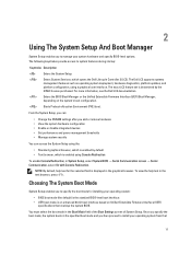
...field is enabled using the: • Standard graphical browser, which is enabled by default • Text browser, which opens the Dell Lifecycle Controller 2 (LC2). Starts Preboot eXecution Environment (PXE) boot. Choosing The System Boot Mode System Setup enables you to halt at startup. 11 Enters the BIOS Boot Manager or the Unified Extensible Firmware Interface (UEFI) Boot Manager, depending on Unified Extensible Firmware Interface (UEFI) specifications that mode. 2 Using The System Setup And Boot Manager System Setup enables you to access the installed operating system...
...field is enabled using the: • Standard graphical browser, which is enabled by default • Text browser, which opens the Dell Lifecycle Controller 2 (LC2). Starts Preboot eXecution Environment (PXE) boot. Choosing The System Boot Mode System Setup enables you to halt at startup. 11 Enters the BIOS Boot Manager or the Unified Extensible Firmware Interface (UEFI) Boot Manager, depending on Unified Extensible Firmware Interface (UEFI) specifications that mode. 2 Using The System Setup And Boot Manager System Setup enables you to access the installed operating system...
Dell PowerEdge M620 Systems Owner's Manual
Page 115
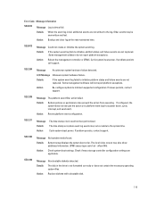
... storage controller configuration settings are not captured. Details If the system event log fails to the system time. Action Reboot the management controller or iDRAC. SEL1204 Message An unknown system hardware failure detected. LCD Message Unknown system hardware failure. Action Review platform event configuration. The time stamp on a platform event (such as power down, cycle, interrupt, and send alert). offset 00h). Details The disk in the drive is full, additional events are not captured. Some management software...
... storage controller configuration settings are not captured. Details If the system event log fails to the system time. Action Reboot the management controller or iDRAC. SEL1204 Message An unknown system hardware failure detected. LCD Message Unknown system hardware failure. Action Review platform event configuration. The time stamp on a platform event (such as power down, cycle, interrupt, and send alert). offset 00h). Details The disk in the drive is full, additional events are not captured. Some management software...
Dell PowerEdge M520 Systems Owner's Manual
Page 11
...; Change the NVRAM settings after you add or remove hardware • View the system hardware configuration • Enable or disable integrated devices • Set performance and power management thresholds • Manage system security You can access the System Setup using a graphical user interface. You must select the boot mode in System Setup, select System BIOS → Serial Communication screen → Serial Communication, select On with Console Redirection. Choosing The System Boot Mode System Setup enables you to install your operating system: • BIOS boot...
...; Change the NVRAM settings after you add or remove hardware • View the system hardware configuration • Enable or disable integrated devices • Set performance and power management thresholds • Manage system security You can access the System Setup using a graphical user interface. You must select the boot mode in System Setup, select System BIOS → Serial Communication screen → Serial Communication, select On with Console Redirection. Choosing The System Boot Mode System Setup enables you to install your operating system: • BIOS boot...

Dell PowerEdge M520 Systems Owner's Manual
Page 17
... the system board. The Slot Disablement feature controls the configuration of the SD card fails, data is set the port address for Serial Over LAN (SOL). The BIOS attempts to set the remote console terminal type. Remote Terminal Type Allows you to set to the active SD card. If any one of PCIe cards installed in the specified slot. Embedded Video Controller Allows you to determine the baud rate automatically. Serial Port Address Allows you to enable the COM port or Console Redirection options...
... the system board. The Slot Disablement feature controls the configuration of the SD card fails, data is set the port address for Serial Over LAN (SOL). The BIOS attempts to set the remote console terminal type. Remote Terminal Type Allows you to set to the active SD card. If any one of PCIe cards installed in the specified slot. Embedded Video Controller Allows you to determine the baud rate automatically. Serial Port Address Allows you to enable the COM port or Console Redirection options...

Dell PowerEdge M520 Systems Owner's Manual
Page 111
... Review platform event configuration. Action Check system boot settings. Action Replace diskette with a bootable disk. 111 SEL0012 Message Could not create or initialize the system event log. If issues persists, contact support. Details System setup displays the system boot order. Details If the system event log fails to minimum supported configuration. Cycle system input power. The local video screen may prevent the action from executing. Action Re-configure system to initialize, platform status and failure events...
... Review platform event configuration. Action Check system boot settings. Action Replace diskette with a bootable disk. 111 SEL0012 Message Could not create or initialize the system event log. If issues persists, contact support. Details System setup displays the system boot order. Details If the system event log fails to minimum supported configuration. Cycle system input power. The local video screen may prevent the action from executing. Action Re-configure system to initialize, platform status and failure events...
Technical Guide
Page 33
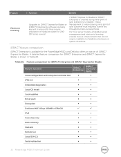
... ∞ ∞ Auto-recovery ∞ ∞ Web GUI ∞ ∞ Remote CLI ∞ ∞ Local/SSH CLI ∞ ∞ Serial redirection ∞ ∞ 33 PowerEdge M520 Technical Guide Table 20. Feature Electronic licensing Function Benefit Upgrades to iDRAC7 Express for Blades or iDRAC7 Enterprise by software licensing key and license portal (may require installation of hardware option for 200500 series servers) If iDRAC7 Express...
... ∞ ∞ Auto-recovery ∞ ∞ Web GUI ∞ ∞ Remote CLI ∞ ∞ Local/SSH CLI ∞ ∞ Serial redirection ∞ ∞ 33 PowerEdge M520 Technical Guide Table 20. Feature Electronic licensing Function Benefit Upgrades to iDRAC7 Express for Blades or iDRAC7 Enterprise by software licensing key and license portal (may require installation of hardware option for 200500 series servers) If iDRAC7 Express...
Technical Guide
Page 44
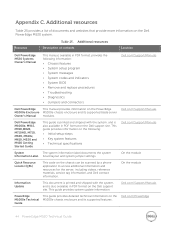
... messages System codes and indicators System BIOS Remove and replace procedures Troubleshooting Diagnostics Jumpers and connectors Dell.com/Support/Manuals Dell PowerEdge This manual provides information on the Dell support site. Appendix C. On the module Information Update This document is printed and shipped with the system, and is also available in PDF format, provides the following : Initial setup steps Key system features Technical specifications Dell.com/Support/Manuals System...
... messages System codes and indicators System BIOS Remove and replace procedures Troubleshooting Diagnostics Jumpers and connectors Dell.com/Support/Manuals Dell PowerEdge This manual provides information on the Dell support site. Appendix C. On the module Information Update This document is printed and shipped with the system, and is also available in PDF format, provides the following : Initial setup steps Key system features Technical specifications Dell.com/Support/Manuals System...


