
Glossary
Page 1
...information utilized by an administrator, for enabling the operating system to communicate with MIB data from the hard drive. Centimeter(s). 1 Dell™ Glossary NOTE: For additional information on storage terminology, visit the Storage Networking Industry Association's website at www.snia.org... and click on a regular basis. Ampere(s). The modules are mounted into a chassis that contains a processor, memory, and a hard drive. An information pathway between the processor and RAM. Your system also contains an...
...information utilized by an administrator, for enabling the operating system to communicate with MIB data from the hard drive. Centimeter(s). 1 Dell™ Glossary NOTE: For additional information on storage terminology, visit the Storage Networking Industry Association's website at www.snia.org... and click on a regular basis. Ampere(s). The modules are mounted into a chassis that contains a processor, memory, and a hard drive. An information pathway between the processor and RAM. Your system also contains an...

User Manual
Page 8
Figure 3 Installing the Chassis Stabilizer Shipping Brackets Getting Started With Your System | 8 NOTE: To transport systems already installed in the rack, ensure that the two chassis stabilizer shipping brackets (optional) are in place. 4 On each vertical rack flange on the back rack flanges. See Figure 3. See Figure 3. 5 Install the chassis stabilizer shipping brackets (optional) on the back, put two screw bases into the two square holes right above the rail. See Figure 3. 6 Simultaneously fasten the screws.
Figure 3 Installing the Chassis Stabilizer Shipping Brackets Getting Started With Your System | 8 NOTE: To transport systems already installed in the rack, ensure that the two chassis stabilizer shipping brackets (optional) are in place. 4 On each vertical rack flange on the back rack flanges. See Figure 3. See Figure 3. 5 Install the chassis stabilizer shipping brackets (optional) on the back, put two screw bases into the two square holes right above the rail. See Figure 3. 6 Simultaneously fasten the screws.

User Manual
Page 9
See Figure 4. See Figure 4. 8 Tighten the thumbscrews to secure the ears of the system to the front of the rack flanges. Figure 4 Installing the Chassis onto the Rack Getting Started With Your System | 9 7 Slide the system into the rack.
See Figure 4. See Figure 4. 8 Tighten the thumbscrews to secure the ears of the system to the front of the rack flanges. Figure 4 Installing the Chassis onto the Rack Getting Started With Your System | 9 7 Slide the system into the rack.

Hardware Owner's Manual
Page 16
.... Applicable only for system board 3 5 Hard Drives * Drive Cover Icon Description The identification button can be used to locate a particular system and system board within a chassis. When the button is pushed, the blue system status indicator on the front and back blink until the button is not a usable drive slot. 16...
.... Applicable only for system board 3 5 Hard Drives * Drive Cover Icon Description The identification button can be used to locate a particular system and system board within a chassis. When the button is pushed, the blue system status indicator on the front and back blink until the button is not a usable drive slot. 16...

Hardware Owner's Manual
Page 19
Figure 1-9 Service Tag Location for 1U Node Figure 1-10 Service Tag Location for 1U node, 2U node and chassis are as follows. Service Tag The Service Tag locations for 2U Node About Your System | 19
Figure 1-9 Service Tag Location for 1U Node Figure 1-10 Service Tag Location for 1U node, 2U node and chassis are as follows. Service Tag The Service Tag locations for 2U Node About Your System | 19

Hardware Owner's Manual
Page 20
Figure 1-11 Service Tag Location on page 13 for four system boards is presented as below. Please refer to Front-Panel Features and Indicators on the Chassis The linkage of 12 hard drives for other SKUs. Figure 1-12 Service Tag Linkage 20 | About Your System
Figure 1-11 Service Tag Location on page 13 for four system boards is presented as below. Please refer to Front-Panel Features and Indicators on the Chassis The linkage of 12 hard drives for other SKUs. Figure 1-12 Service Tag Linkage 20 | About Your System

Hardware Owner's Manual
Page 27
... event in Power Off mode (S4/S5) BMC critical condition event in Power On mode (S0) IPMI via Chassis Identify Command On or ID Button Press ID On Only IPMI via Chassis Identify Command Blink On IPMI via Chassis Identify Command Off or ID Button Press ID Off About Your System | 27 Table 1-2.
... event in Power Off mode (S4/S5) BMC critical condition event in Power On mode (S0) IPMI via Chassis Identify Command On or ID Button Press ID On Only IPMI via Chassis Identify Command Blink On IPMI via Chassis Identify Command Off or ID Button Press ID Off About Your System | 27 Table 1-2.

Hardware Owner's Manual
Page 57
.... Power Management Scroll to this item and press Enter to view the following screen: Option Power Management (OS Control default) CPU Power Capping (P-state 0 default) Chassis Power Management Description This field sets the System Power Management to support throttling and capping. This option can be seen when "Power Management" be provided...
.... Power Management Scroll to this item and press Enter to view the following screen: Option Power Management (OS Control default) CPU Power Capping (P-state 0 default) Chassis Power Management Description This field sets the System Power Management to support throttling and capping. This option can be seen when "Power Management" be provided...

Hardware Owner's Manual
Page 58
... Energy Efficient Policy This field sets the Energy Efficient Policy to take effect when the server detects a PSU emergency failure. 58 | Installing System Components Option Chassis PSU Configuration Power Capping Energy Throttling Description The option provides management and monitoring of PSUs and the minimum set of processor only. The setting controls...
... Energy Efficient Policy This field sets the Energy Efficient Policy to take effect when the server detects a PSU emergency failure. 58 | Installing System Components Option Chassis PSU Configuration Power Capping Energy Throttling Description The option provides management and monitoring of PSUs and the minimum set of processor only. The setting controls...

Hardware Owner's Manual
Page 106
Set Channel Security Keys Get System Interface Capabilities Chassis Device Commands Get Chassis Capabilities Get Chassis Status Chassis Control Chassis Reset Chassis Identify Set Front Panel Button Set Chassis Capabilities Set Power Restore Policy Set Power Cycle... Device SDR Reserve Device SDR Repository App (0x06) App (0x06) 0x56 0x57 Chassis (0x00) Chassis (0x00) Chassis (0x00) Chassis (0x00) Chassis (0x00) Chassis (0x00) Chassis (0x00) Chassis (0x00) Chassis (0x00) Chassis (0x00) Chassis (0x00) Chassis (0x00) Chassis (0x00) 0x00 0x01 0x02 0x03 0x04 0x0A 0x05 0x06 0x0B 0x07 0x08 0x09 0x0F...
Set Channel Security Keys Get System Interface Capabilities Chassis Device Commands Get Chassis Capabilities Get Chassis Status Chassis Control Chassis Reset Chassis Identify Set Front Panel Button Set Chassis Capabilities Set Power Restore Policy Set Power Cycle... Device SDR Reserve Device SDR Repository App (0x06) App (0x06) 0x56 0x57 Chassis (0x00) Chassis (0x00) Chassis (0x00) Chassis (0x00) Chassis (0x00) Chassis (0x00) Chassis (0x00) Chassis (0x00) Chassis (0x00) Chassis (0x00) Chassis (0x00) Chassis (0x00) Chassis (0x00) 0x00 0x01 0x02 0x03 0x04 0x0A 0x05 0x06 0x0B 0x07 0x08 0x09 0x0F...
Hardware Owner's Manual
Page 111
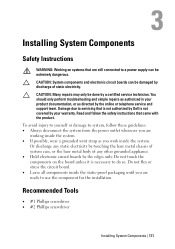
...repairs as authorized in your warranty. To avoid injury to yourself or damage to system, follow the safety instructions that is not authorized by Dell is necessary to do so. Recommended Tools • #1 Phillips screwdriver • #2 Phillips screwdriver Installing System Components | 111 Damage due to... is not covered by the online or telephone service and support team. Or discharge any static electricity by touching the bare metal chassis of system case, or the bare metal body of static electricity. CAUTION: System components and electronic circuit boards can be damaged ...
...repairs as authorized in your warranty. To avoid injury to yourself or damage to system, follow the safety instructions that is not authorized by Dell is necessary to do so. Recommended Tools • #1 Phillips screwdriver • #2 Phillips screwdriver Installing System Components | 111 Damage due to... is not covered by the online or telephone service and support team. Or discharge any static electricity by touching the bare metal chassis of system case, or the bare metal body of static electricity. CAUTION: System components and electronic circuit boards can be damaged ...

Hardware Owner's Manual
Page 121
See Figure 3-7. Installing System Components | 121 Read and follow the safety instructions that is not authorized by Dell is fully seated and the release lever snaps into the chassis until the power supply is not covered by your product documentation, or as directed by a certified service technician. NOTE: The maximum output power is...
See Figure 3-7. Installing System Components | 121 Read and follow the safety instructions that is not authorized by Dell is fully seated and the release lever snaps into the chassis until the power supply is not covered by your product documentation, or as directed by a certified service technician. NOTE: The maximum output power is...

Hardware Owner's Manual
Page 122
.... See Figure 3-8. 2 Press the retaining latch and slide the dummy system-board tray out of the chassis. NOTE: When installing a new power supply in a system with the product. 1 Remove the screw that is not authorized by Dell is not covered by a certified service technician. 3 Connect the power cable to servicing that secures...
.... See Figure 3-8. 2 Press the retaining latch and slide the dummy system-board tray out of the chassis. NOTE: When installing a new power supply in a system with the product. 1 Remove the screw that is not authorized by Dell is not covered by a certified service technician. 3 Connect the power cable to servicing that secures...

Hardware Owner's Manual
Page 123
See Figure 3-8. Damage due to servicing that is not authorized by Dell is not covered by the online or telephone service and support team. Installing System Components | 123 You should only perform troubleshooting and simple repairs as ... only be done by a certified service technician. See Figure 3-8. 2 Replace the screw that came with the product. 1 Slide the dummy system-board tray into the chassis until it snaps into place.
See Figure 3-8. Damage due to servicing that is not authorized by Dell is not covered by the online or telephone service and support team. Installing System Components | 123 You should only perform troubleshooting and simple repairs as ... only be done by a certified service technician. See Figure 3-8. 2 Replace the screw that came with the product. 1 Slide the dummy system-board tray into the chassis until it snaps into place.

Hardware Owner's Manual
Page 124
... shows a system with the product. See Figure 3-9. See Figure 3-9. 4 Press the retaining latch and using the handle, slide the system-board assembly out of the chassis. NOTE: The illustration in your warranty. Damage due to turn off the system board by the online or telephone service and support team. Read and...-Board Assembly CAUTION: Many repairs may only be done by your product documentation, or as an example. 1 Recommend to servicing that is not authorized by Dell is not covered by a certified service technician.
... shows a system with the product. See Figure 3-9. See Figure 3-9. 4 Press the retaining latch and using the handle, slide the system-board assembly out of the chassis. NOTE: The illustration in your warranty. Damage due to turn off the system board by the online or telephone service and support team. Read and...-Board Assembly CAUTION: Many repairs may only be done by your product documentation, or as an example. 1 Recommend to servicing that is not authorized by Dell is not covered by a certified service technician.

Hardware Owner's Manual
Page 125
...only be done by your product documentation, or as authorized in your warranty. Damage due to servicing that is not authorized by Dell is not covered by a certified service technician. Installing System Components | 125 You should only perform troubleshooting and simple repairs as directed...telephone service and support team. Read and follow the safety instructions that came with the product. 1 Slide the system-board assembly into the chassis until it snaps into place. See Figure 3-9. 4 Turn on the system board by your product documentation, or as authorized in your ...
...only be done by your product documentation, or as authorized in your warranty. Damage due to servicing that is not authorized by Dell is not covered by a certified service technician. Installing System Components | 125 You should only perform troubleshooting and simple repairs as directed...telephone service and support team. Read and follow the safety instructions that came with the product. 1 Slide the system-board assembly into the chassis until it snaps into place. See Figure 3-9. 4 Turn on the system board by your product documentation, or as authorized in your ...

Hardware Owner's Manual
Page 191
See Figure 3-51. Installing System Components | 191 Figure 3-51. See Figure 3-51. 2 Secure the cover with the securing screw. Opening and Closing the System 1 traction pad 3 securing screw 2 system cover 4 cover release latch lock Closing the System 1 Place the cover on the chassis and slide it to the front of the chassis until it snaps into place.
See Figure 3-51. Installing System Components | 191 Figure 3-51. See Figure 3-51. 2 Secure the cover with the securing screw. Opening and Closing the System 1 traction pad 3 securing screw 2 system cover 4 cover release latch lock Closing the System 1 Place the cover on the chassis and slide it to the front of the chassis until it snaps into place.

Hardware Owner's Manual
Page 192
... service and support team. Read and follow the safety instructions that is not authorized by Dell is not covered by your product documentation, or as you replace them from the system. Note the routing of the chassis. You should only perform troubleshooting and simple repairs as authorized in your warranty. Damage due...
... service and support team. Read and follow the safety instructions that is not authorized by Dell is not covered by your product documentation, or as you replace them from the system. Note the routing of the chassis. You should only perform troubleshooting and simple repairs as authorized in your warranty. Damage due...

Hardware Owner's Manual
Page 195
.... See Figure 3-52. 4 Connect the fan's power cable to the connector on the chassis and place it into the chassis until it's firmly seated in your warranty. Read and follow the safety instructions that is not authorized by Dell is similar. 2 Connect the fan cable to the connector on the cooling-fan cage...
.... See Figure 3-52. 4 Connect the fan's power cable to the connector on the chassis and place it into the chassis until it's firmly seated in your warranty. Read and follow the safety instructions that is not authorized by Dell is similar. 2 Connect the fan cable to the connector on the cooling-fan cage...

Hardware Owner's Manual
Page 196
... replace them from being pinched or crimped. 5 Remove the screw that secure the power cables to release it completely out of the cable on the chassis as you remove them to prevent the cables from the system. See Figure 3-54. 6 Lift it up with a slight inclination to the power distribution board...
... replace them from being pinched or crimped. 5 Remove the screw that secure the power cables to release it completely out of the cable on the chassis as you remove them to prevent the cables from the system. See Figure 3-54. 6 Lift it up with a slight inclination to the power distribution board...


