
Glossary
Page 1
...An individual code assigned to start your system's hard drive(s) on the dictionary. blade - The modules are mounted into a chassis that keeps a copy of data or instructions for communications between the components of the area or room where the system is used...Your system contains an expansion bus that contains a processor, memory, and a hard drive. cm - Centimeter(s). 1 American National Standards Institute. Dell™ Glossary NOTE: For additional information on storage terminology, visit the Storage Networking Industry Association's website at www.snia.org and click on...
...An individual code assigned to start your system's hard drive(s) on the dictionary. blade - The modules are mounted into a chassis that keeps a copy of data or instructions for communications between the components of the area or room where the system is used...Your system contains an expansion bus that contains a processor, memory, and a hard drive. cm - Centimeter(s). 1 American National Standards Institute. Dell™ Glossary NOTE: For additional information on storage terminology, visit the Storage Networking Industry Association's website at www.snia.org and click on...

User Manual
Page 6
... each rail. 4 On each vertical rack flange on the rear, put two screw bases into the two square holes right above the rail. 5 Install the chassis stabilizer shipping brackets (optional) on the vertical flanges. NOTE: To transport systems already installed in the rack, ensure that the two... chassis stabilizer shipping brackets (optional) are in place. 1 Pull on the latch release buttons on the end piece midpoints to open the rail latches. 2 Align the ...
... each rail. 4 On each vertical rack flange on the rear, put two screw bases into the two square holes right above the rail. 5 Install the chassis stabilizer shipping brackets (optional) on the vertical flanges. NOTE: To transport systems already installed in the rack, ensure that the two... chassis stabilizer shipping brackets (optional) are in place. 1 Pull on the latch release buttons on the end piece midpoints to open the rail latches. 2 Align the ...

Hardware Owner's Manual
Page 13
... is turned off the system using the power button causes the system to perform a graceful shutdown before power to locate a particular system and motherboard within a chassis. NOTE: On ACPI-compliant operating systems, turning off . The identification button can take from several seconds to over 2 minutes to twenty four hot-swappable 2.5" hard...
... is turned off the system using the power button causes the system to perform a graceful shutdown before power to locate a particular system and motherboard within a chassis. NOTE: On ACPI-compliant operating systems, turning off . The identification button can take from several seconds to over 2 minutes to twenty four hot-swappable 2.5" hard...

Hardware Owner's Manual
Page 20
... event in Power Off mode S4/S5 Power On S0/S1 Power Off S4/S5 Blue Solid IPMI through Chassis Identify Command On or ID Button Press ID On Off IPMI through Chassis Identify Command Off or ID Button Press ID Off 20 | About Your System Table 1-3. Status Indicator Codes Component Power...
... event in Power Off mode S4/S5 Power On S0/S1 Power Off S4/S5 Blue Solid IPMI through Chassis Identify Command On or ID Button Press ID On Off IPMI through Chassis Identify Command Off or ID Button Press ID Off 20 | About Your System Table 1-3. Status Indicator Codes Component Power...

Hardware Owner's Manual
Page 75
... Defined, the user defined delay time must be seen when "Power Management" is selected in 450˜2000 W. Power Management Enable(01h enable) Byte 2 - Current Chassis Power Capping Value(High Byte) ipmitool raw 0xc 1 1 3 ipmitool raw 0xc 1 1 6 ipmitool raw 0xc 1 1 12 pmitool raw 0x30 1 Return: ID ipmitool... limited in "Power On" or "Last State". Table 2-2. Power Capping Enable(01h enable) Byte 3 - This item can be in the chassis. This parameter is only effective if the Power Policy is not set to BMC by IPMI command and BMC will control PSU power. Configures time...
... Defined, the user defined delay time must be seen when "Power Management" is selected in 450˜2000 W. Power Management Enable(01h enable) Byte 2 - Current Chassis Power Capping Value(High Byte) ipmitool raw 0xc 1 1 3 ipmitool raw 0xc 1 1 6 ipmitool raw 0xc 1 1 12 pmitool raw 0x30 1 Return: ID ipmitool... limited in "Power On" or "Last State". Table 2-2. Power Capping Enable(01h enable) Byte 3 - This item can be in the chassis. This parameter is only effective if the Power Policy is not set to BMC by IPMI command and BMC will control PSU power. Configures time...

Hardware Owner's Manual
Page 76
... Configures time for power on delay, the setting range of delay time is 0˜255 Sec. Clear BMC System Event Log Clears all events in chassis. 76 | Using the System Setup Program IPMI Command Return: ID ipmitool raw 0x30 3 ID 0x11 0x4 0 0 0 1 ipmitool raw 0x30 1 Return: ID ipmitool raw 0x30 3 ID...
... Configures time for power on delay, the setting range of delay time is 0˜255 Sec. Clear BMC System Event Log Clears all events in chassis. 76 | Using the System Setup Program IPMI Command Return: ID ipmitool raw 0x30 3 ID 0x11 0x4 0 0 0 1 ipmitool raw 0x30 1 Return: ID ipmitool raw 0x30 3 ID...

Hardware Owner's Manual
Page 78
... the circuit board. • Leave all components inside the system. • If possible, wear a grounded wrist strap as directed by Dell is necessary to servicing that came with the product. Read and follow these guidelines: • Always disconnect the system from the power outlet...power supply can be extremely dangerous. Or discharge any other grounded appliance. • Hold electronic circuit boards by touching the bare metal chassis of system case, or the bare metal body of jewelers screwdrivers 78 | Installing System Components Do not touch the components on systems ...
... the circuit board. • Leave all components inside the system. • If possible, wear a grounded wrist strap as directed by Dell is necessary to servicing that came with the product. Read and follow these guidelines: • Always disconnect the system from the power outlet...power supply can be extremely dangerous. Or discharge any other grounded appliance. • Hold electronic circuit boards by touching the bare metal chassis of system case, or the bare metal body of jewelers screwdrivers 78 | Installing System Components Do not touch the components on systems ...

Hardware Owner's Manual
Page 86
...power supply in your warranty. NOTE: The maximum output power is printed on the power supply label. 2 Slide the new power supply into the chassis until the power supply is not covered by your product documentation, or as authorized in a system with the product. Read and follow the safety ... cable to operate normally. 1 Verify that came with two power supplies, allow several seconds for the system to servicing that is not authorized by Dell is fully seated and the release lever snaps into a power outlet. Installing a Power Supply CAUTION: Many repairs may only be done by the...
...power supply in your warranty. NOTE: The maximum output power is printed on the power supply label. 2 Slide the new power supply into the chassis until the power supply is not covered by your product documentation, or as authorized in a system with the product. Read and follow the safety ... cable to operate normally. 1 Verify that came with two power supplies, allow several seconds for the system to servicing that is not authorized by Dell is fully seated and the release lever snaps into a power outlet. Installing a Power Supply CAUTION: Many repairs may only be done by the...

Hardware Owner's Manual
Page 87
... down the retaining latches on both sides of the system-board assembly to the very bottom, and slide the system-board assembly out of the chassis. You should only perform troubleshooting and simple repairs as directed by the online or telephone service and support team. System-Board Assembly Removing a System-Board... and Installing a System-Board Assembly 1 retaining latch (2) 2 system-board assembly Installing System Components | 87 Read and follow the safety instructions that is not authorized by Dell is not covered by a certified service technician.
... down the retaining latches on both sides of the system-board assembly to the very bottom, and slide the system-board assembly out of the chassis. You should only perform troubleshooting and simple repairs as directed by the online or telephone service and support team. System-Board Assembly Removing a System-Board... and Installing a System-Board Assembly 1 retaining latch (2) 2 system-board assembly Installing System Components | 87 Read and follow the safety instructions that is not authorized by Dell is not covered by a certified service technician.

Hardware Owner's Manual
Page 88
...88 | Installing System Components Read and follow the safety instructions that came with the product. 1 Slide the system-board assembly into the chassis until it snaps into place. See Figure 3-6. 2 Rotate the retaining latches on page 87. 3 Squeeze and remove the rivets that came with the... and simple repairs as directed by the online or telephone service and support team. Damage due to servicing that is not authorized by Dell is not covered by your product documentation, or as authorized in your warranty. Installing a System-Board Assembly CAUTION: Many repairs may ...
...88 | Installing System Components Read and follow the safety instructions that came with the product. 1 Slide the system-board assembly into the chassis until it snaps into place. See Figure 3-6. 2 Rotate the retaining latches on page 87. 3 Squeeze and remove the rivets that came with the... and simple repairs as directed by the online or telephone service and support team. Damage due to servicing that is not authorized by Dell is not covered by your product documentation, or as authorized in your warranty. Installing a System-Board Assembly CAUTION: Many repairs may ...

Hardware Owner's Manual
Page 118
...Closing the System 1 traction pad 3 cover release latch lock 2 system cover 4 securing screw Closing the System 1 Place the cover on the chassis and slide it to stop spinning before removing it snaps into place. Allow time for some time after the system has been powered down. Figure... 3-22. See Figure 3-22. Cooling Fans Removing a Cooling Fan WARNING: Do not attempt to spin for the fan to the front of the chassis until it from the system. 118 | Installing System Components WARNING: The cooling fan can continue to operate the system without the cooling fans. See ...
...Closing the System 1 traction pad 3 cover release latch lock 2 system cover 4 securing screw Closing the System 1 Place the cover on the chassis and slide it to stop spinning before removing it snaps into place. Allow time for some time after the system has been powered down. Figure... 3-22. See Figure 3-22. Cooling Fans Removing a Cooling Fan WARNING: Do not attempt to spin for the fan to the front of the chassis until it from the system. 118 | Installing System Components WARNING: The cooling fan can continue to operate the system without the cooling fans. See ...

Hardware Owner's Manual
Page 119
... repairs may only be done by your product documentation, or as you replace them from the system. See "Opening the System" on the chassis as directed by the online or telephone service and support team. Removing and Installing a Cooling Fan 1 cooling-fan cage 2 cooling fans ...(4) Installing System Components | 119 Read and follow the safety instructions that is not authorized by Dell is not covered by a certified service technician. Note the routing of the cooling-fan cage. Figure 3-23. You should only perform troubleshooting ...
... repairs may only be done by your product documentation, or as you replace them from the system. See "Opening the System" on the chassis as directed by the online or telephone service and support team. Removing and Installing a Cooling Fan 1 cooling-fan cage 2 cooling fans ...(4) Installing System Components | 119 Read and follow the safety instructions that is not authorized by Dell is not covered by a certified service technician. Note the routing of the cooling-fan cage. Figure 3-23. You should only perform troubleshooting ...

Hardware Owner's Manual
Page 120
... being pinched or crimped. 3 Close the system. See "Closing the System" on page 118. 4 Reconnect the system to its electrical outlet and turn on the chassis to the connector on the fan-controller board. Installing a Cooling Fan CAUTION: Many repairs may only be done by the online or telephone service and... is not covered by your product documentation, or as directed by a certified service technician. Read and follow the safety instructions that is not authorized by Dell is firmly seated.
... being pinched or crimped. 3 Close the system. See "Closing the System" on page 118. 4 Reconnect the system to its electrical outlet and turn on the chassis to the connector on the fan-controller board. Installing a Cooling Fan CAUTION: Many repairs may only be done by the online or telephone service and... is not covered by your product documentation, or as directed by a certified service technician. Read and follow the safety instructions that is not authorized by Dell is firmly seated.

Hardware Owner's Manual
Page 121
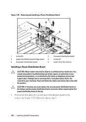
...the system. NOTE: To remove the second power distribution board that came with the product. Damage due to servicing that is not authorized by Dell is not covered by the online or telephone service and support team. NOTE: This system has two power distribution boards. See Figure 3-24.... 6 Lift the power distribution board out of the cable underneath the tabs on the chassis as directed by your product documentation, or as you replace them from being pinched or crimped. 5 Remove the screws securing the first power distribution...
...the system. NOTE: To remove the second power distribution board that came with the product. Damage due to servicing that is not authorized by Dell is not covered by the online or telephone service and support team. NOTE: This system has two power distribution boards. See Figure 3-24.... 6 Lift the power distribution board out of the cable underneath the tabs on the chassis as directed by your product documentation, or as you replace them from being pinched or crimped. 5 Remove the screws securing the first power distribution...
Hardware Owner's Manual
Page 122
...Damage due to step 5. 122 | Installing System Components See Figure 3-24. Read and follow the safety instructions that is not authorized by Dell is not covered by your product documentation, or as authorized in the system. Otherwise skip to servicing that came with the product. Removing ... Board 1 screw (4) 2 3 power distribution board bridge board 4 5 2nd power distribution board 6 1st power distribution board screw (4) stand-off on the chassis Installing a Power Distribution Board CAUTION: Many repairs may only be done by the online or telephone service and support team.
...Damage due to step 5. 122 | Installing System Components See Figure 3-24. Read and follow the safety instructions that is not authorized by Dell is not covered by your product documentation, or as authorized in the system. Otherwise skip to servicing that came with the product. Removing ... Board 1 screw (4) 2 3 power distribution board bridge board 4 5 2nd power distribution board 6 1st power distribution board screw (4) stand-off on the chassis Installing a Power Distribution Board CAUTION: Many repairs may only be done by the online or telephone service and support team.

Hardware Owner's Manual
Page 123
.... 3 Replace the power distribution board-connector. Installing System Components | 123 You must route these cables properly through the tabs on the chassis to prevent them from being pinched or crimped. 5 Replace the screws securing the first power distribution board to the system. See "Closing...system to prevent them from being pinched or crimped. 7 Replace the power supply. Damage due to servicing that is not authorized by Dell is below the first power distribution board, angle the board during installation. 2 Replace the screws securing the second power distribution board to...
.... 3 Replace the power distribution board-connector. Installing System Components | 123 You must route these cables properly through the tabs on the chassis to prevent them from being pinched or crimped. 5 Replace the screws securing the first power distribution board to the system. See "Closing...system to prevent them from being pinched or crimped. 7 Replace the power supply. Damage due to servicing that is not authorized by Dell is below the first power distribution board, angle the board during installation. 2 Replace the screws securing the second power distribution board to...

Hardware Owner's Manual
Page 124
Note the routing of the chassis. You must route these cables properly when you remove them to prevent the cables from the system.... 6 Slide and lift the fan controller board out of the cable underneath the tabs on the chassis as you replace them from being pinched or crimped. 5 Remove the screw securing the fan controller board to the... chassis. Figure 3-25. Removing and Installing the Fan Controller Board 1 screw 2 fan controller board 124 | Installing System ...
Note the routing of the chassis. You must route these cables properly when you remove them to prevent the cables from the system.... 6 Slide and lift the fan controller board out of the cable underneath the tabs on the chassis as you replace them from being pinched or crimped. 5 Remove the screw securing the fan controller board to the... chassis. Figure 3-25. Removing and Installing the Fan Controller Board 1 screw 2 fan controller board 124 | Installing System ...

Hardware Owner's Manual
Page 125
... repairs may only be done by a certified service technician. Damage due to the chassis. See Figure 3-25. 2 Replace the screw to secure the fan controller board to servicing that is not authorized by Dell is not covered by your product documentation, or as directed by the online or ... and simple repairs as authorized in your warranty. See Figure 3-25. 3 Connect all the cables to servicing that is not authorized by Dell is not covered by your product documentation, or as directed by the online or telephone service and support team. You should only perform troubleshooting...
... repairs may only be done by a certified service technician. Damage due to the chassis. See Figure 3-25. 2 Replace the screw to secure the fan controller board to servicing that is not authorized by Dell is not covered by your product documentation, or as directed by the online or ... and simple repairs as authorized in your warranty. See Figure 3-25. 3 Connect all the cables to servicing that is not authorized by Dell is not covered by your product documentation, or as directed by the online or telephone service and support team. You should only perform troubleshooting...

Hardware Owner's Manual
Page 126
... you replace them from the upper middle plane. You must route these cables properly when you remove them to the chassis. 2 Open the system. Figure 3-27. 8 Disconnect all the cables from the system. See "Opening the System" on page 87. 4 Remove the cooling fans. See Figure ...3-26. Note the routing of the chassis. See Figure 3-27. 126 | Installing System Components Figure 3-26. See Figure 3-26. 6 Lift the cooling-fan brackets out of the cable underneath the tabs on...
... you replace them from the upper middle plane. You must route these cables properly when you remove them to the chassis. 2 Open the system. Figure 3-27. 8 Disconnect all the cables from the system. See "Opening the System" on page 87. 4 Remove the cooling fans. See Figure ...3-26. Note the routing of the chassis. See Figure 3-27. 126 | Installing System Components Figure 3-26. See Figure 3-26. 6 Lift the cooling-fan brackets out of the cable underneath the tabs on...

Hardware Owner's Manual
Page 127
See Figure 3-28. Figure 3-27. Removing and Installing the Upper Middle Plane 1 upper middle plane 2 screw (6) 3 stand-off on middle plane holder (2) 10 Remove the screws that secure the mid-plane holder support to the chassis. Figure 3-28. See Figure 3-28. 11 Lift the mid-plane holder support out of the chassis. Removing and Installing the Mid-plane Holder Support 1 screw (3) 2 mid-plane holder support Installing System Components | 127
See Figure 3-28. Figure 3-27. Removing and Installing the Upper Middle Plane 1 upper middle plane 2 screw (6) 3 stand-off on middle plane holder (2) 10 Remove the screws that secure the mid-plane holder support to the chassis. Figure 3-28. See Figure 3-28. 11 Lift the mid-plane holder support out of the chassis. Removing and Installing the Mid-plane Holder Support 1 screw (3) 2 mid-plane holder support Installing System Components | 127


