
Glossary
Page 2
... as 208.77.188.166. Error checking and correction. ERA allows you to communicate with a peripheral. expansion bus - A math coprocessor, for the serial ports on your network server using a remote access controller. CPU - Double-data rate. See also memory module. ESM - Your system contains an expansion bus that allows the processor to perform remote, or "out-ofband," server management on your system. control panel - device driver - A comprehensive set of automatically assigning an IP address to a client system. A method...
... as 208.77.188.166. Error checking and correction. ERA allows you to communicate with a peripheral. expansion bus - A math coprocessor, for the serial ports on your network server using a remote access controller. CPU - Double-data rate. See also memory module. ESM - Your system contains an expansion bus that allows the processor to perform remote, or "out-ofband," server management on your system. control panel - device driver - A comprehensive set of automatically assigning an IP address to a client system. A method...

Glossary
Page 3
...; operating systems can be differentiated from computational activity. F - FAT - A type of electronic chip that can optionally use a FAT file system structure. FSB - Gram(s). A keyboard is an input device, and a monitor is the data path and physical interface between the system board and storage devices. Integrated drive electronics. Integrated Dell Remote Access Controller. InfiniBand - InfiniBand offers point-to organize and keep track of processors with networked storage devices. Internet Protocol version...
...; operating systems can be differentiated from computational activity. F - FAT - A type of electronic chip that can optionally use a FAT file system structure. FSB - Gram(s). A keyboard is an input device, and a monitor is the data path and physical interface between the system board and storage devices. Integrated drive electronics. Integrated Dell Remote Access Controller. InfiniBand - InfiniBand offers point-to organize and keep track of processors with networked storage devices. Internet Protocol version...

Glossary
Page 5
... is monitored and managed using Dell OpenManage™ Server Administrator. Managed object format is provided by software. Network Attached Storage. Milliampere-hour(s). A system used for implementing shared storage on a network. Megabyte(s); 1,048,576 bytes. Megabits per second. A specific location, usually expressed as integrated memory (ROM and RAM) and add-in your system that are optimized to mean 1,000,000 bytes. A portable flash memory storage device integrated with a USB connector. NIC - Media Access Control address. MBR - A type of data redundancy...
... is monitored and managed using Dell OpenManage™ Server Administrator. Managed object format is provided by software. Network Attached Storage. Milliampere-hour(s). A system used for implementing shared storage on a network. Megabyte(s); 1,048,576 bytes. Megabits per second. A specific location, usually expressed as integrated memory (ROM and RAM) and add-in your system that are optimized to mean 1,000,000 bytes. A portable flash memory storage device integrated with a USB connector. NIC - Media Access Control address. MBR - A type of data redundancy...

Glossary
Page 7
... the POST. A network architecture that enables remote networkattached storage devices to appear to a server to its contents even after you are prohibited from editing or deleting. Serial Advanced Technology Attachment. A standard interface between the system board and storage devices. SD card - SDRAM - sec - System event log. A legacy I /O bus interface with a 9-pin connector that you turn off your system. Redundant array of providing data redundancy. Read-only memory. Allows hard drives to report errors and failures to...
... the POST. A network architecture that enables remote networkattached storage devices to appear to a server to its contents even after you are prohibited from editing or deleting. Serial Advanced Technology Attachment. A standard interface between the system board and storage devices. SD card - SDRAM - sec - System event log. A legacy I /O bus interface with a 9-pin connector that you turn off your system. Redundant array of providing data redundancy. Read-only memory. Allows hard drives to report errors and failures to...

Glossary
Page 8
... access to I/O devices. U-DIMM - A port on each end of space used by an operating system, where each disk used to connect to remotely monitor and manage workstations. A battery-powered unit that allows you may use several stripes on the devices or by setting features such as the processor(s), RAM, controllers for peripherals, and various ROM chips. USB - SNMP - A virtual disk may need to configure your system's hardware and customize the system's operation by changing settings in the cable. Super video graphics array...
... access to I/O devices. U-DIMM - A port on each end of space used by an operating system, where each disk used to connect to remotely monitor and manage workstations. A battery-powered unit that allows you may use several stripes on the devices or by setting features such as the processor(s), RAM, controllers for peripherals, and various ROM chips. USB - SNMP - A virtual disk may need to configure your system's hardware and customize the system's operation by changing settings in the cable. Super video graphics array...
User Manual
Page 5
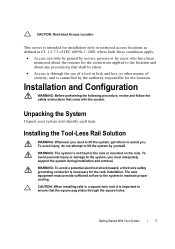
... location. Installation and Configuration WARNING: Before performing the following procedure, review and follow the safety instructions that shall be gained by service persons or by users who have been instructed about the reasons for the restrictions applied to the location and about any precautions that came with the system. To avoid injury, do not attempt to the rack or mounted on the rails. WARNING...
... location. Installation and Configuration WARNING: Before performing the following procedure, review and follow the safety instructions that shall be gained by service persons or by users who have been instructed about the reasons for the restrictions applied to the location and about any precautions that came with the system. To avoid injury, do not attempt to the rack or mounted on the rails. WARNING...

Hardware Owner's Manual
Page 27
... BMC IP address source to DHCP. If users set IP address source to set console redirection: 1 Enter the BIOS setup menu. 2 Select server. 3 Select remote access configuration. 4 Enable Remote Access. 5 Select serial port number: • When COM1 is provided by the system, the system must provide support for the serial console must be capable of the console redirection is a Flash ROM-resident utility that redirects input and output over a serial or modem connection. Console Redirection The console redirection allows a remote user to a serial port...
... BMC IP address source to DHCP. If users set IP address source to set console redirection: 1 Enter the BIOS setup menu. 2 Select server. 3 Select remote access configuration. 4 Enable Remote Access. 5 Select serial port number: • When COM1 is provided by the system, the system must provide support for the serial console must be capable of the console redirection is a Flash ROM-resident utility that redirects input and output over a serial or modem connection. Console Redirection The console redirection allows a remote user to a serial port...

Hardware Owner's Manual
Page 40
... driver when install OS, windows 2008 R2 had native support.) Two SATA (Port 4 and Port 5) share one IDE channel (could be either Primary or Secondary channel) from IDE (PATA) controller. IDE Configuration Scroll to this item and press Enter to view the following screen: Option OnChip SATA Channel (Enabled default) OnChip SATA Type (Native IDE default) SATA IDE Combined Mode (Enabled default) Hard Disk Write Protect Description Select this item to enable or disable...
... driver when install OS, windows 2008 R2 had native support.) Two SATA (Port 4 and Port 5) share one IDE channel (could be either Primary or Secondary channel) from IDE (PATA) controller. IDE Configuration Scroll to this item and press Enter to view the following screen: Option OnChip SATA Channel (Enabled default) OnChip SATA Type (Native IDE default) SATA IDE Combined Mode (Enabled default) Hard Disk Write Protect Description Select this item to enable or disable...
Hardware Owner's Manual
Page 58
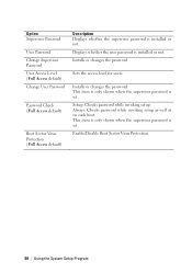
...each boot. This item is only shown when the supervisor password is installed or not. Installs or changes the password. Option Supervisor Password User Password Change Supervisor Password User Access Level (Full Access default) Change User Password Password Check (Full Access default) Boot Sector Virus Protection (Full Access default) Description Displays whether the supervisor password is set . Sets the access level for users. Setup: Checks password while invoking setup. Enable/Disable Boot Sector Virus Protection. 58 | Using the System Setup Program Installs or changes the...
...each boot. This item is only shown when the supervisor password is installed or not. Installs or changes the password. Option Supervisor Password User Password Change Supervisor Password User Access Level (Full Access default) Change User Password Password Check (Full Access default) Boot Sector Virus Protection (Full Access default) Description Displays whether the supervisor password is set . Sets the access level for users. Setup: Checks password while invoking setup. Enable/Disable Boot Sector Virus Protection. 58 | Using the System Setup Program Installs or changes the...
Hardware Owner's Manual
Page 61
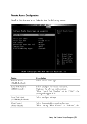
...When setting "Flow Control" to view the following screen: Option Remote Access (Disabled default) Serial Port Number (COM1 default) Serial Port Mode (115200 8,n,1 default) Flow Control (None default) Description Select remote access type. Remote Access Configuration Scroll to this item and press Enter to "Software", the Using the System Setup Program | 61 When "Serial Port Number" set to "COM2", the setting will support SOL. Select serial port settings. Select flow control for console redirection. Select serial port for console redirection. Make sure the selected port is enabled...
...When setting "Flow Control" to view the following screen: Option Remote Access (Disabled default) Serial Port Number (COM1 default) Serial Port Mode (115200 8,n,1 default) Flow Control (None default) Description Select remote access type. Remote Access Configuration Scroll to this item and press Enter to "Software", the Using the System Setup Program | 61 When "Serial Port Number" set to "COM2", the setting will support SOL. Select serial port settings. Select flow control for console redirection. Select serial port for console redirection. Make sure the selected port is enabled...

Hardware Owner's Manual
Page 77
... Configuration PCI Configuration -> Active State Power Management Configuration L3 Power Control DRAM Prefetcher Hardware Prefetcher Software Prefetcher Power Management Performance Settings Option Enabled D4 Token 4878 Enabled 48BA Enabled 0174 Enabled 48BE Max. 021F Performance Power Saving Features SATA-AHCI Ports Auto Clk Ctrl SATA-IDE Ports Auto Clk Ctrl Coherent HT Link Speed Non-Coherent HT Link Speed Disabled Disabled Disabled HT3 HT3 2600MHz Non-Coherent HT Link Width PCI-E Slot ASPM Onboard LAN ASPM Mezzing Slot ASPM NB-SB Link ASPM 16 bits Disabled Disabled Disabled...
... Configuration PCI Configuration -> Active State Power Management Configuration L3 Power Control DRAM Prefetcher Hardware Prefetcher Software Prefetcher Power Management Performance Settings Option Enabled D4 Token 4878 Enabled 48BA Enabled 0174 Enabled 48BE Max. 021F Performance Power Saving Features SATA-AHCI Ports Auto Clk Ctrl SATA-IDE Ports Auto Clk Ctrl Coherent HT Link Speed Non-Coherent HT Link Speed Disabled Disabled Disabled HT3 HT3 2600MHz Non-Coherent HT Link Width PCI-E Slot ASPM Onboard LAN ASPM Mezzing Slot ASPM NB-SB Link ASPM 16 bits Disabled Disabled Disabled...
Hardware Owner's Manual
Page 90
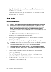
... covered by your product documentation, or as directed by the online or telephone service and support team. See Figure 3-7. 2 Replace the rivets to secure the air ducts to cool before removing it. Allow the heat sink to the system-board assembly and heat sinks. See Figure 3-8. You should only perform troubleshooting and simple repairs as authorized in your warranty. See "Removing a System-Board...
... covered by your product documentation, or as directed by the online or telephone service and support team. See Figure 3-7. 2 Replace the rivets to secure the air ducts to cool before removing it. Allow the heat sink to the system-board assembly and heat sinks. See Figure 3-8. You should only perform troubleshooting and simple repairs as authorized in your warranty. See "Removing a System-Board...

Hardware Owner's Manual
Page 94
.... 6 Using a clean lint-free cloth, remove the thermal grease from support.dell.com. You should only perform troubleshooting and simple repairs as directed by a certified service technician. See Figure 3-9. Be careful not to bend the pins in the ZIF socket. 3 With the release lever on the processor socket in the open position, align the processor with the socket keys and set the processor lightly...
.... 6 Using a clean lint-free cloth, remove the thermal grease from support.dell.com. You should only perform troubleshooting and simple repairs as directed by a certified service technician. See Figure 3-9. Be careful not to bend the pins in the ZIF socket. 3 With the release lever on the processor socket in the open position, align the processor with the socket keys and set the processor lightly...

Hardware Owner's Manual
Page 151
... BIOS to the serial port. 2 Swap the serial interface cable with another working cable, and turn on each USB device one at a time. 8 If a device causes the same problem, power down all USB ports are enabled. 4 Replace the keyboard/mouse with another working keyboard/mouse. If all troubleshooting fails, see "Switch and Jumper Settings" on page 176 for instructions on setting the NVRAM_CLR jumper inside your keyboard is not functioning, you can also use remote access. If the problem...
... BIOS to the serial port. 2 Swap the serial interface cable with another working cable, and turn on each USB device one at a time. 8 If a device causes the same problem, power down all USB ports are enabled. 4 Replace the keyboard/mouse with another working keyboard/mouse. If all troubleshooting fails, see "Switch and Jumper Settings" on page 176 for instructions on setting the NVRAM_CLR jumper inside your keyboard is not functioning, you can also use remote access. If the problem...
Hardware Owner's Manual
Page 152
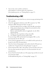
... problem is resolved, replace the serial device. Remove and reinstall the drivers if applicable. See the NIC's documentation. • Change the auto-negotiation setting, if possible. • Use another connector on page 19. • If the link indicator does not light, check all network cables are using a NIC card instead of the proper type and do not exceed the maximum length. See "NIC Indicators (BMC Management Port)" on the switch or hub. See the documentation for each network device...
... problem is resolved, replace the serial device. Remove and reinstall the drivers if applicable. See the NIC's documentation. • Change the auto-negotiation setting, if possible. • Use another connector on page 19. • If the link indicator does not light, check all network cables are using a NIC card instead of the proper type and do not exceed the maximum length. See "NIC Indicators (BMC Management Port)" on the switch or hub. See the documentation for each network device...
Hardware Owner's Manual
Page 153
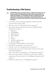
.... • Hard drives • SAS backplane • Expansion-card • Power supplies • Fans • Air ducts • Processors and heat sinks • Memory modules 4 Let the system dry thoroughly for at least 24 hours. 5 Reinstall the components you removed. See "Closing the System" on page 179. 8 If the system starts properly, shut down the system and reinstall the expansion card that came with the product. 1 Turn off...
.... • Hard drives • SAS backplane • Expansion-card • Power supplies • Fans • Air ducts • Processors and heat sinks • Memory modules 4 Let the system dry thoroughly for at least 24 hours. 5 Reinstall the components you removed. See "Closing the System" on page 179. 8 If the system starts properly, shut down the system and reinstall the expansion card that came with the product. 1 Turn off...
Hardware Owner's Manual
Page 154
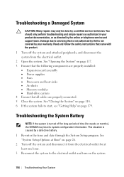
... not covered by your product documentation, or as directed by the online or telephone service and support team. See "Closing the System" on page 118. 6 If the system fails to start, see "Getting Help" on page 117. 3 Ensure that the following components are properly installed: • Expansion-card assembly • Power supplies • Fans • Processors and heat sinks • Air ducts • Memory modules • Hard-drive...
... not covered by your product documentation, or as directed by the online or telephone service and support team. See "Closing the System" on page 118. 6 If the system fails to start, see "Getting Help" on page 117. 3 Ensure that the following components are properly installed: • Expansion-card assembly • Power supplies • Fans • Processors and heat sinks • Air ducts • Memory modules • Hard-drive...
Hardware Owner's Manual
Page 159
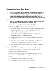
... instructions that the required device drivers for your controller card are installed and are configured in your product documentation, or as authorized in a RAID array, perform the following steps: a. Before you proceed, back up all files on the hard drive. 1 If your system has a RAID controller and your warranty. See "Removing a Hard Drive From a Hard-Drive Carrier" on page 26. Exit the configuration utility and allow the system to boot to servicing that the hard drive...
... instructions that the required device drivers for your controller card are installed and are configured in your product documentation, or as authorized in a RAID array, perform the following steps: a. Before you proceed, back up all files on the hard drive. 1 If your system has a RAID controller and your warranty. See "Removing a Hard Drive From a Hard-Drive Carrier" on page 26. Exit the configuration utility and allow the system to boot to servicing that the hard drive...

Hardware Owner's Manual
Page 182
... 99 fan controller board, 123 front panel, 140 hard drive, 81 hard drive blank, 80 heat sink, 90 hot-swap hard drive, 81 memory modules (DIMMs), 110 middle planes, 125 power distribution board, 121 power supply, 85 processor, 92 sensor board, 143 system board, 115 system board assembly, 87 replacing system battery, 113 S safety, 78 SAS controller daughter card troubleshooting, 160 SAS RAID controller daughter card troubleshooting, 160 startup accessing system features, 10 support contacting Dell, 179 system closing, 118 opening, 117 system board connectors, 164 installing, 116 jumper settings...
... 99 fan controller board, 123 front panel, 140 hard drive, 81 hard drive blank, 80 heat sink, 90 hot-swap hard drive, 81 memory modules (DIMMs), 110 middle planes, 125 power distribution board, 121 power supply, 85 processor, 92 sensor board, 143 system board, 115 system board assembly, 87 replacing system battery, 113 S safety, 78 SAS controller daughter card troubleshooting, 160 SAS RAID controller daughter card troubleshooting, 160 startup accessing system features, 10 support contacting Dell, 179 system closing, 118 opening, 117 system board connectors, 164 installing, 116 jumper settings...

Using the Baseboard Management Controller
Page 32
... ISO. Maintenance Firmware Update Use the Firmware Update feature to upgrade to start or stop the redirection of the managed system cannot be unplugged and the Web GUI cannot be closed. 1 Select "Maintenance" in the BMC firmware package: Compiled BMC firmware code and data Web-based user interface, JPEG, and other user interface data files Default configuration files NOTE: The firmware update retains the current BMC settings. You can choose the Floppy/USB drive from client...
... ISO. Maintenance Firmware Update Use the Firmware Update feature to upgrade to start or stop the redirection of the managed system cannot be unplugged and the Web GUI cannot be closed. 1 Select "Maintenance" in the BMC firmware package: Compiled BMC firmware code and data Web-based user interface, JPEG, and other user interface data files Default configuration files NOTE: The firmware update retains the current BMC settings. You can choose the Floppy/USB drive from client...


