
Getting Started Guide
Page 11
... - The connectors on the monitor's cable connector. Connecting the Power Cable(s) Connect the system's power cable(s) to the system and, if a monitor is used, connect the monitor's power cable to plug into a grounded electrical outlet or a separate power source such as an uninterrupted power supply or a power distribution unit. Plug the other end of your system have...
... - The connectors on the monitor's cable connector. Connecting the Power Cable(s) Connect the system's power cable(s) to the system and, if a monitor is used, connect the monitor's power cable to plug into a grounded electrical outlet or a separate power source such as an uninterrupted power supply or a power distribution unit. Plug the other end of your system have...

Getting Started Guide
Page 15
VGA connector 8 MB Power AC power supply (per power supply) Wattage Voltage Heat dissipation Wattage Voltage Heat dissipation Wattage Voltage Heat dissipation Wattage Voltage Heat dissipation Maximum inrush current Batteries (per system board) System battery .../60 Hz, 8.6-7.2 A 5432 BTU/hr maximum Under typical line conditions and over the entire system ambient operating range, the inrush current may reach 25 A per power supply for 10 ms or less CR 2032 3.0-V lithium ion coin cell 3.7 V lithium ion battery pack Physical Height Width Depth Weight (maximum configuration) Weight (empty) 8.7 cm...
VGA connector 8 MB Power AC power supply (per power supply) Wattage Voltage Heat dissipation Wattage Voltage Heat dissipation Wattage Voltage Heat dissipation Wattage Voltage Heat dissipation Maximum inrush current Batteries (per system board) System battery .../60 Hz, 8.6-7.2 A 5432 BTU/hr maximum Under typical line conditions and over the entire system ambient operating range, the inrush current may reach 25 A per power supply for 10 ms or less CR 2032 3.0-V lithium ion coin cell 3.7 V lithium ion battery pack Physical Height Width Depth Weight (maximum configuration) Weight (empty) 8.7 cm...

Hardware Owner's Manual
Page 3
Contents 1 About Your System 11 Accessing System Features During Startup 11 Front-Panel Features and Indicators 12 Hard-Drive Indicator Patterns 15 Back-Panel Features and Indicators 16 NIC Indicator Codes 18 Power and System Board Indicator Codes 20 Power Supply Indicator Codes 21 BMC Heart Beat LED 22 POST Error Codes 23 Collecting System Event Log for Investigation . . . 23 Other Information You May Need 33 2 Using the System Setup Program 35 Start Menu 35 System Setup Options at Boot 36 Console Redirection 36 Main Menu 37 Main Screen 37 Contents 3
Contents 1 About Your System 11 Accessing System Features During Startup 11 Front-Panel Features and Indicators 12 Hard-Drive Indicator Patterns 15 Back-Panel Features and Indicators 16 NIC Indicator Codes 18 Power and System Board Indicator Codes 20 Power Supply Indicator Codes 21 BMC Heart Beat LED 22 POST Error Codes 23 Collecting System Event Log for Investigation . . . 23 Other Information You May Need 33 2 Using the System Setup Program 35 Start Menu 35 System Setup Options at Boot 36 Console Redirection 36 Main Menu 37 Main Screen 37 Contents 3

Hardware Owner's Manual
Page 5
... Carrier 56 Installing a Hard Drive Carrier 57 Removing a Hard Drive From a Hard-Drive Carrier 57 Installing a Hard Drive Into a Hard-Drive Carrier 58 Power Supplies 59 Removing a Power Supply 59 Installing a Power Supply 60 System-Board Assembly 61 Removing a System-Board Assembly 61 Installing a System-Board Assembly 62 Cooling Shroud 63 Removing the Cooling Shroud 63...
... Carrier 56 Installing a Hard Drive Carrier 57 Removing a Hard Drive From a Hard-Drive Carrier 57 Installing a Hard Drive Into a Hard-Drive Carrier 58 Power Supplies 59 Removing a Power Supply 59 Installing a Power Supply 60 System-Board Assembly 61 Removing a System-Board Assembly 61 Installing a System-Board Assembly 62 Cooling Shroud 63 Removing the Cooling Shroud 63...

Hardware Owner's Manual
Page 8
Troubleshooting a Wet System 117 Troubleshooting a Damaged System 118 Troubleshooting the System Battery 118 Troubleshooting Power Supplies 119 Troubleshooting System Cooling Problems 120 Troubleshooting a Fan 120 Troubleshooting System Memory 121 Troubleshooting a Hard Drive 123 Troubleshooting a Storage Controller 124 Troubleshooting Expansion Cards 125 ...
Troubleshooting a Wet System 117 Troubleshooting a Damaged System 118 Troubleshooting the System Battery 118 Troubleshooting Power Supplies 119 Troubleshooting System Cooling Problems 120 Troubleshooting a Fan 120 Troubleshooting System Memory 121 Troubleshooting a Hard Drive 123 Troubleshooting a Storage Controller 124 Troubleshooting Expansion Cards 125 ...

Hardware Owner's Manual
Page 14
..., the video monitor can be used to display an image, depending on indicator lights when the system power is pushed again. 14 About Your System The power button controls the DC power supply output to the system is turned off. NOTE: To force an ungraceful shutdown, press and hold the... power button for 5 seconds. The identification button can take from several seconds to over 2 minutes to locate a particular ...
..., the video monitor can be used to display an image, depending on indicator lights when the system power is pushed again. 14 About Your System The power button controls the DC power supply output to the system is turned off. NOTE: To force an ungraceful shutdown, press and hold the... power button for 5 seconds. The identification button can take from several seconds to over 2 minutes to locate a particular ...

Hardware Owner's Manual
Page 16
.... Embedded 10/100/1000 NIC connectors. Back-Panel Features and Indicators Figure 1-8. Back Panel-Four System Boards 1 2 3 4 5 67 8 9 10 Item Indicator, Button, Icon or Connector 1 Power supply 2 (PS2) 2 Power supply 1 (PS1) 3 USB connectors (2) 4 System identification indicator 5 Ethernet connector 1 6 Ethernet connector 2 7 KVM over IP Port 8 Serial connector Description 470W / 750W / 1100W/ 1400W 470W / 750W / 1100W...
.... Embedded 10/100/1000 NIC connectors. Back-Panel Features and Indicators Figure 1-8. Back Panel-Four System Boards 1 2 3 4 5 67 8 9 10 Item Indicator, Button, Icon or Connector 1 Power supply 2 (PS2) 2 Power supply 1 (PS1) 3 USB connectors (2) 4 System identification indicator 5 Ethernet connector 1 6 Ethernet connector 2 7 KVM over IP Port 8 Serial connector Description 470W / 750W / 1100W/ 1400W 470W / 750W / 1100W...

Hardware Owner's Manual
Page 17
... installed in the system. NOTE: On ACPI-compliant operating systems, turning off . The power button controls the DC power supply output to the system. 10 Power-on indicator/ power button (system board 1) The power-on indicator lights when the system power is turned off the system using the power button causes the system to perform a graceful shutdown before...
... installed in the system. NOTE: On ACPI-compliant operating systems, turning off . The power button controls the DC power supply output to the system. 10 Power-on indicator/ power button (system board 1) The power-on indicator lights when the system power is turned off the system using the power button causes the system to perform a graceful shutdown before...

Hardware Owner's Manual
Page 21
Power Supply Indicator Codes Figure 1-14. Power Supply Status Indicator 1 2 1 power supply 2 power supply indicator Power Supply Status Indicator Steady green Steady yellow Yellow off Condition Power supply is on (AC OK/DC OK) or in standby mode (90 VAC-264 VAC) Power supply faulty (UVP/OVP/OCP/SCP/OTP/Fan Fault) Power supply is off or AC input voltage is out of normal operating range (90 VAC-264 VAC) About Your System 21
Power Supply Indicator Codes Figure 1-14. Power Supply Status Indicator 1 2 1 power supply 2 power supply indicator Power Supply Status Indicator Steady green Steady yellow Yellow off Condition Power supply is on (AC OK/DC OK) or in standby mode (90 VAC-264 VAC) Power supply faulty (UVP/OVP/OCP/SCP/OTP/Fan Fault) Power supply is off or AC input voltage is out of normal operating range (90 VAC-264 VAC) About Your System 21

Hardware Owner's Manual
Page 53
Damage due to servicing that is not authorized by Dell is necessary to your system, follow the safety instructions that are still connected to use the component for the installation. CAUTION: System components and electronic ... bare metal body of jewelers screwdrivers Installing System Components 53 Read and follow these guidelines: • Always disconnect the system from the power outlet whenever you are ready to a power supply can be done by a certified service technician. Do not flex or stress the circuit board. • Leave all components inside the static...
Damage due to servicing that is not authorized by Dell is necessary to your system, follow the safety instructions that are still connected to use the component for the installation. CAUTION: System components and electronic ... bare metal body of jewelers screwdrivers Installing System Components 53 Read and follow these guidelines: • Always disconnect the system from the power outlet whenever you are ready to a power supply can be done by a certified service technician. Do not flex or stress the circuit board. • Leave all components inside the static...

Hardware Owner's Manual
Page 54
... that is not authorized by Dell is not covered by a certified service technician. Figure 3-1. CAUTION: This system must be done by your product documentation, or as authorized in this section shows a system with the product. Inside the System 1 2 3 4 5 6 1 system board assembly (4) 3 power distribution board (2) 5 hard-drive bay 2 power supply (2) 4 cooling fan (4) 6 hard drive (12...
... that is not authorized by Dell is not covered by a certified service technician. Figure 3-1. CAUTION: This system must be done by your product documentation, or as authorized in this section shows a system with the product. Inside the System 1 2 3 4 5 6 1 system board assembly (4) 3 power distribution board (2) 5 hard-drive bay 2 power supply (2) 4 cooling fan (4) 6 hard drive (12...

Hardware Owner's Manual
Page 59
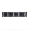
... for the maximum number of processors, hard drives, and memory modules. Power Supplies Table 3-1. Damage due to servicing that came with the product. Installing System Components 59 Removing a Power Supply CAUTION: Many repairs may only be done by your product documentation, or... the system, including any attached peripherals, and disconnect the system from the electrical outlet. 2 Disconnect the power cable from the power source and the power supply. Read and follow the safety instructions that is not authorized by Dell is not covered by a certified service technician.
... for the maximum number of processors, hard drives, and memory modules. Power Supplies Table 3-1. Damage due to servicing that came with the product. Installing System Components 59 Removing a Power Supply CAUTION: Many repairs may only be done by your product documentation, or... the system, including any attached peripherals, and disconnect the system from the electrical outlet. 2 Disconnect the power cable from the power source and the power supply. Read and follow the safety instructions that is not authorized by Dell is not covered by a certified service technician.
Hardware Owner's Manual
Page 60
... requires one power supply to servicing that is not authorized by Dell is fully seated and the release lever snaps into place. Figure 3-5. Damage due to operate normally. 1 Verify that came with the product. NOTE: The maximum output power is printed on the power supply label. 2 Slide the new power supply into the chassis until the power supply is not...
... requires one power supply to servicing that is not authorized by Dell is fully seated and the release lever snaps into place. Figure 3-5. Damage due to operate normally. 1 Verify that came with the product. NOTE: The maximum output power is printed on the power supply label. 2 Slide the new power supply into the chassis until the power supply is not...

Hardware Owner's Manual
Page 61
..., and disconnect the system from its status. Read and follow the safety instructions that came with two power supplies, allow several seconds for the system to recognize the power supply and determine its electrical outlet. 2 Disconnect all the external cables from the system board. 3 Remove ...the screw that is not authorized by Dell is not covered by your product documentation, or as directed by a certified service ...
..., and disconnect the system from its status. Read and follow the safety instructions that came with two power supplies, allow several seconds for the system to recognize the power supply and determine its electrical outlet. 2 Disconnect all the external cables from the system board. 3 Remove ...the screw that is not authorized by Dell is not covered by your product documentation, or as directed by a certified service ...

Hardware Owner's Manual
Page 94
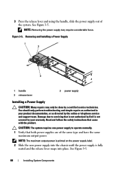
... pinched or crimped. 3 Close the system. Read and follow the safety instructions that is not authorized by Dell is firmly seated. NOTE: This system has two power distribution boards. See "Removing a Power Supply" on page 91. 3 Remove the power supply. See "Closing the System" on page 92. 4 Reconnect the system to the connector on the system...
... pinched or crimped. 3 Close the system. Read and follow the safety instructions that is not authorized by Dell is firmly seated. NOTE: This system has two power distribution boards. See "Removing a Power Supply" on page 91. 3 Remove the power supply. See "Closing the System" on page 92. 4 Reconnect the system to the connector on the system...
Hardware Owner's Manual
Page 97
... 3-25. 6 Slide and lift the fan controller board out of the cable underneath the tabs on page 91. 3 Remove the power distribution boards. See "Installing a Power Supply" on the system, including any attached peripherals, and disconnect the system from the system. Damage due to the chassis. Note the routing...may only be done by the online or telephone service and support team. Read and follow the safety instructions that is not authorized by Dell is not covered by your product documentation, or as you replace them from its electrical outlet and turn on page 60. 8 Close ...
... 3-25. 6 Slide and lift the fan controller board out of the cable underneath the tabs on page 91. 3 Remove the power distribution boards. See "Installing a Power Supply" on the system, including any attached peripherals, and disconnect the system from the system. Damage due to the chassis. Note the routing...may only be done by the online or telephone service and support team. Read and follow the safety instructions that is not authorized by Dell is not covered by your product documentation, or as you replace them from its electrical outlet and turn on page 60. 8 Close ...

Hardware Owner's Manual
Page 117
See "Opening the System" on page 92. 7 Reconnect the system to servicing that is not authorized by Dell is not covered by the online or telephone service and support team. See "Installing System Components" on page 143. If the system does not start ...the system fails to start properly, see "Getting Help" on page 53. • Cooling shroud • Hard drives • SAS backplane • Expansion-card • Power supplies • Fans • Processors and heat sinks • Memory modules 4 Let the system dry thoroughly for at least 24 hours. 5 Reinstall the components you removed...
See "Opening the System" on page 92. 7 Reconnect the system to servicing that is not authorized by Dell is not covered by the online or telephone service and support team. See "Installing System Components" on page 143. If the system does not start ...the system fails to start properly, see "Getting Help" on page 53. • Cooling shroud • Hard drives • SAS backplane • Expansion-card • Power supplies • Fans • Processors and heat sinks • Memory modules 4 Let the system dry thoroughly for at least 24 hours. 5 Reinstall the components you removed...
Hardware Owner's Manual
Page 118
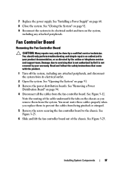
...system fails to start, see "Getting Help" on page 91. 3 Ensure that the following components are properly installed: • Expansion-card assembly • Power supplies • Fans • Processors and heat sinks • Memory modules • Hard-drive carriers • Cooling shroud 4 Ensure that all cables are ... system and disconnect it from the electrical outlet. 2 Open the system. Read and follow the safety instructions that is not authorized by Dell is turned off for long periods of time (for at Boot" on the system. 118 Troubleshooting Your System See "Opening the System...
...system fails to start, see "Getting Help" on page 91. 3 Ensure that the following components are properly installed: • Expansion-card assembly • Power supplies • Fans • Processors and heat sinks • Memory modules • Hard-drive carriers • Cooling shroud 4 Ensure that all cables are ... system and disconnect it from the electrical outlet. 2 Open the system. Read and follow the safety instructions that is not authorized by Dell is turned off for long periods of time (for at Boot" on the system. 118 Troubleshooting Your System See "Opening the System...

Hardware Owner's Manual
Page 119
... and support team. NOTE: Some software may be caused by software rather than by the power supply's fault indicator. See "Power Supplies" on page 84. NOTE: After installing a power supply, allow several seconds for the system to determine if it . See "Power and System Board Indicator Codes" on page 143. If the problem is functioning properly. Troubleshooting... extended periods of time can cause the system to speed up or slow down. Read and follow the safety instructions that came with only one power supply must be done by Dell is working properly.
... and support team. NOTE: Some software may be caused by software rather than by the power supply's fault indicator. See "Power Supplies" on page 84. NOTE: After installing a power supply, allow several seconds for the system to determine if it . See "Power and System Board Indicator Codes" on page 143. If the problem is functioning properly. Troubleshooting... extended periods of time can cause the system to speed up or slow down. Read and follow the safety instructions that came with only one power supply must be done by Dell is working properly.
Hardware Owner's Manual
Page 120
...not authorized by Dell is not covered by the online or telephone service and support team. Ensure that is not authorized by your warranty. Damage due to servicing that none of the following conditions exist: • System cover, cooling shroud, drive blank, power supply blank, or ...front or back filler panel is removed. • Ambient temperature is too high. • External airflow is obstructed. • Cables inside the system obstruct airflow. • An individual cooling fan is not covered by Dell is removed or has failed. ...
...not authorized by Dell is not covered by the online or telephone service and support team. Ensure that is not authorized by your warranty. Damage due to servicing that none of the following conditions exist: • System cover, cooling shroud, drive blank, power supply blank, or ...front or back filler panel is removed. • Ambient temperature is too high. • External airflow is obstructed. • Cables inside the system obstruct airflow. • An individual cooling fan is not covered by Dell is removed or has failed. ...


