

Dell Systems Hardware Owners Manual
Page 27
Memory remapping relocates memory space 3 GB~4 GB to the space above 4 GB with this feature disabled/enabled. Menu Fields Settings Memory Operating Voltage Auto* 1.5V 1.35V Memory Remapping (3 GB - 4 GB) Enabled* Disabled Memory Configuration Figure 2-8. Memory Configuration Screen Comments Memory operating voltage will be set automatically by the Memory initialization code and depends upon the installed DIMM's capability and the memory configuration of the system or set it 1.5/1.35 volts. Using the System Setup Program 27
Memory remapping relocates memory space 3 GB~4 GB to the space above 4 GB with this feature disabled/enabled. Menu Fields Settings Memory Operating Voltage Auto* 1.5V 1.35V Memory Remapping (3 GB - 4 GB) Enabled* Disabled Memory Configuration Figure 2-8. Memory Configuration Screen Comments Memory operating voltage will be set automatically by the Memory initialization code and depends upon the installed DIMM's capability and the memory configuration of the system or set it 1.5/1.35 volts. Using the System Setup Program 27
Dell Systems Hardware Owners Manual
Page 33
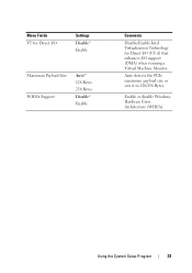
Using the System Setup Program 33 Menu Fields VT for Direct I/O Settings Disable* Enable Maximum Payload Size WHEA Support Auto* 128 Bytes 256 Bytes Disable* Enable Comments Disable/Enable Intel Virtualization Technology for Direct I/O (VT-d) that enhances I/O support (DMA) when running a Virtual Machine Monitor. Auto detects the PCIe maximum payload size or sets it to 128/256 Bytes. Enable or disable Windows Hardware Error Architecture (WHEA).
Using the System Setup Program 33 Menu Fields VT for Direct I/O Settings Disable* Enable Maximum Payload Size WHEA Support Auto* 128 Bytes 256 Bytes Disable* Enable Comments Disable/Enable Intel Virtualization Technology for Direct I/O (VT-d) that enhances I/O support (DMA) when running a Virtual Machine Monitor. Auto detects the PCIe maximum payload size or sets it to 128/256 Bytes. Enable or disable Windows Hardware Error Architecture (WHEA).

Dell Systems Hardware Owners Manual
Page 40
.... Enter IP address in IP6 mode. The minimum value is 0 and the maximum is 16. 0 means no retry. Menu Fields Internet Protocol Settings IP4* IP6 Autoconfigure Connect Retry Count Connection Establishing Time out ISID Enable DHCP Initiator IP address Initiator Subnet Mask Gateway Target Name Disabled* Enabled Target IP address Target Port 40 Using the System Setup Program Comments Initiator IP address is system assigned...
.... Enter IP address in IP6 mode. The minimum value is 0 and the maximum is 16. 0 means no retry. Menu Fields Internet Protocol Settings IP4* IP6 Autoconfigure Connect Retry Count Connection Establishing Time out ISID Enable DHCP Initiator IP address Initiator Subnet Mask Gateway Target Name Disabled* Enabled Target IP address Target Port 40 Using the System Setup Program Comments Initiator IP address is system assigned...

Dell Systems Hardware Owners Manual
Page 52
Set BMC LAN Configuration Figure 2-21. Select to configure LAN channel parameters statically or dynamically (DHCP). Do nothing option will not modify any BMC network parameters during BIOS phase. 52 Using the System Setup Program Set BMC LAN Configuration Screen Menu Fields Settings Server Management/BMC Network Configuration BMC LAN Port Configuration Dedicated-NIC Shared-NIC* BMC NIC IP Source Static DHCP* Comments BMC LAN Port Configuration.
Set BMC LAN Configuration Figure 2-21. Select to configure LAN channel parameters statically or dynamically (DHCP). Do nothing option will not modify any BMC network parameters during BIOS phase. 52 Using the System Setup Program Set BMC LAN Configuration Screen Menu Fields Settings Server Management/BMC Network Configuration BMC LAN Port Configuration Dedicated-NIC Shared-NIC* BMC NIC IP Source Static DHCP* Comments BMC LAN Port Configuration.
Dell Systems Hardware Owners Manual
Page 55
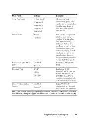
... are full, a 'stop the data flow. VT100: ASCII char set . Hardware flow control uses two wires to stop ' signal can be matched on the other side. VT-UTF8 Combo Key Support Disabled Enabled* Enable VT-UTF8 combination key support for accurate screen display. Change the client-side console utility settings to map Unicode chars onto 1 or more bytes. Menu Fields Settings Comments Serial Port Mode 115200 8-n-1* 57600 8-n-1 38400 8-n-1 19200 8-n-1 9600 8-n-1 Selects serial port transmission speed.
... are full, a 'stop the data flow. VT100: ASCII char set . Hardware flow control uses two wires to stop ' signal can be matched on the other side. VT-UTF8 Combo Key Support Disabled Enabled* Enable VT-UTF8 combination key support for accurate screen display. Change the client-side console utility settings to map Unicode chars onto 1 or more bytes. Menu Fields Settings Comments Serial Port Mode 115200 8-n-1* 57600 8-n-1 38400 8-n-1 19200 8-n-1 9600 8-n-1 Selects serial port transmission speed.
Dell Systems Hardware Owners Manual
Page 73
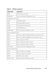
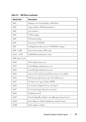
... AMI error codes Recovery Progress Codes 0xF0 0xF1 0xF2 0xF3 0xF4 Recovery condition triggered by firmware (Auto recovery) Recovery condition triggered by user (Forced recovery) Recovery process started Recovery firmware image is found Recovery firmware image is loaded 0xF5-0xF7 Reserved for future AMI progress codes Recovery Error Codes 0xF8 Recovery PPI is not available 0xF9 Recovery capsule is not found 0xFA 0xFB - 0xFF Invalid recovery capsule Reserved for future AMI error codes Using the System Setup...
... AMI error codes Recovery Progress Codes 0xF0 0xF1 0xF2 0xF3 0xF4 Recovery condition triggered by firmware (Auto recovery) Recovery condition triggered by user (Forced recovery) Recovery process started Recovery firmware image is found Recovery firmware image is loaded 0xF5-0xF7 Reserved for future AMI progress codes Recovery Error Codes 0xF8 Recovery PPI is not available 0xF9 Recovery capsule is not found 0xFA 0xFB - 0xFF Invalid recovery capsule Reserved for future AMI error codes Using the System Setup...
Dell Systems Hardware Owners Manual
Page 76
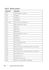
... IDE initialization is started IDE Reset IDE Detect IDE Enable 0xA4 0xA5 0xA6 0xA7 0xA8 SCSI initialization is started SCSI Reset SCSI Detect SCSI Enable Setup Verifying Password 0xA9 0xAA 0xAB 0xAC Start of Setup Reserved for ASL (see ASL Status Codes section below) Setup Input Wait Reserved for ASL (see ASL Status Codes section below) 0xAD 0xAE 0xAF 0xB0 Ready To Boot event Legacy Boot event Exit Boot Services event Runtime Set Virtual Address MAP Begin 76 Using the System Setup Program
... IDE initialization is started IDE Reset IDE Detect IDE Enable 0xA4 0xA5 0xA6 0xA7 0xA8 SCSI initialization is started SCSI Reset SCSI Detect SCSI Enable Setup Verifying Password 0xA9 0xAA 0xAB 0xAC Start of Setup Reserved for ASL (see ASL Status Codes section below) Setup Input Wait Reserved for ASL (see ASL Status Codes section below) 0xAD 0xAE 0xAF 0xB0 Ready To Boot event Legacy Boot event Exit Boot Services event Runtime Set Virtual Address MAP Begin 76 Using the System Setup Program
Dell Systems Hardware Owners Manual
Page 77
... Runtime Set Virtual Address MAP End Legacy Option ROM Initialization System Reset USB hot plug PCI bus hot plug 0xB6 0xB7 0xB8 - 0xBF 0xC0 - 0xCF Clean-up of NVRAM Configuration Reset (reset of the Architectural Protocols are found No Console Input Devices are not available 0xD4 0xD5 0xD6 0xD7 PCI resource allocation error. Out of Resources No Space for future AMI codes OEM BDS initialization codes DXE Error Codes 0xD0 CPU initialization error 0xD1...
... Runtime Set Virtual Address MAP End Legacy Option ROM Initialization System Reset USB hot plug PCI bus hot plug 0xB6 0xB7 0xB8 - 0xBF 0xC0 - 0xCF Clean-up of NVRAM Configuration Reset (reset of the Architectural Protocols are found No Console Input Devices are not available 0xD4 0xD5 0xD6 0xD7 PCI resource allocation error. Out of Resources No Space for future AMI codes OEM BDS initialization codes DXE Error Codes 0xD0 CPU initialization error 0xD1...

Dell Systems Hardware Owners Manual
Page 80
... LED when MRC errors happen. wrong DIMM population): • "Major error code" -> "Minor error code" -> "DIMM location" -> "0" -> ... (repeat) 80 Using the System Setup Program Table 2-12. no specific DIMM location errors (ex. OEM Reserved Checkpoint Ranges (continued) Status Code Description 0x3F - 0x4E 0x80 - 0x8F 0xC0 - 0xCF OEM PEI post memory initialization codes OEM DXE initialization codes OEM BDS initialization codes Intel Memory Reference Code Checkpoints The BIOS will be (with 1 second interval): • For no memory detected...
... LED when MRC errors happen. wrong DIMM population): • "Major error code" -> "Minor error code" -> "DIMM location" -> "0" -> ... (repeat) 80 Using the System Setup Program Table 2-12. no specific DIMM location errors (ex. OEM Reserved Checkpoint Ranges (continued) Status Code Description 0x3F - 0x4E 0x80 - 0x8F 0xC0 - 0xCF OEM PEI post memory initialization codes OEM DXE initialization codes OEM BDS initialization codes Intel Memory Reference Code Checkpoints The BIOS will be (with 1 second interval): • For no memory detected...

Dell Systems Hardware Owners Manual
Page 128
... controls on the monitor are not too low. Power Supply and Chassis Issues • Verify if the chassis and power supply are attached correctly and securely. 128 Troubleshooting If the installed memory is plugged in and turned on. • Ensure all cables are connected properly between the monitor and the system. • Check that all cable connections, both internal and external, are compatible with the processor model. Most monitors employ indicator LEDs showing status. Supported Processor List...
... controls on the monitor are not too low. Power Supply and Chassis Issues • Verify if the chassis and power supply are attached correctly and securely. 128 Troubleshooting If the installed memory is plugged in and turned on. • Ensure all cables are connected properly between the monitor and the system. • Check that all cable connections, both internal and external, are compatible with the processor model. Most monitors employ indicator LEDs showing status. Supported Processor List...

Dell Systems Hardware Owners Manual
Page 130
... enough memory installed and disk space available. 130 Troubleshooting For more details). If the BMC is working, try again. • If the network is reporting an error, see "View System Event Log" on the system. Installation Problems Perform the following checks if you cannot access the BIOS Setup Utility, clear the CMOS by performing the following steps: 1 Turn off the system. If you are troubleshooting an installation problem: • Check all cable and power connections (including all rack cable connections...
... enough memory installed and disk space available. 130 Troubleshooting For more details). If the BMC is working, try again. • If the network is reporting an error, see "View System Event Log" on the system. Installation Problems Perform the following checks if you cannot access the BIOS Setup Utility, clear the CMOS by performing the following steps: 1 Turn off the system. If you are troubleshooting an installation problem: • Check all cable and power connections (including all rack cable connections...

Dell Systems Hardware Owners Manual
Page 131
... user configuration data. BMC Firmware Update The BMC (Baseboard Management Controller) firmware can be updated using various ways, including of remotely or locally, and can be receiving AC power. Check the AC power cord to make sure that all peripherals, one at a time, and try to the external connectors on your system. Update Utilities This chapter provides information about the update utilities. The update should be achieved by IPMI command or by utilities. Troubleshooting External Connections...
... user configuration data. BMC Firmware Update The BMC (Baseboard Management Controller) firmware can be updated using various ways, including of remotely or locally, and can be receiving AC power. Check the AC power cord to make sure that all peripherals, one at a time, and try to the external connectors on your system. Update Utilities This chapter provides information about the update utilities. The update should be achieved by IPMI command or by utilities. Troubleshooting External Connections...
Dell Systems Hardware Owners Manual
Page 136
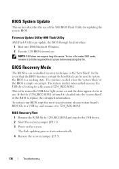
... the USB drive light comes on the system. BIOS System Update This section describes the use of the AMI BIOS Flash Utility for a file named 5230_REC.ROM. BIOS Recovery Mode The BIOS has an embedded recovery technique in use. The flash updating process starts automatically. 4 Remove the recovery jumper (J13.3). 136 Troubleshooting The routine is empty or corrupt. This is loaded into DOS/Microsoft Windows. 2 Execute 5230BIOS(version).exe. Firmware Update Utility-AMI Flash Utility AMI Flash Utility can be in the 'boot...
... the USB drive light comes on the system. BIOS System Update This section describes the use of the AMI BIOS Flash Utility for a file named 5230_REC.ROM. BIOS Recovery Mode The BIOS has an embedded recovery technique in use. The flash updating process starts automatically. 4 Remove the recovery jumper (J13.3). 136 Troubleshooting The routine is empty or corrupt. This is loaded into DOS/Microsoft Windows. 2 Execute 5230BIOS(version).exe. Firmware Update Utility-AMI Flash Utility AMI Flash Utility can be in the 'boot...

Using the Baseboard Management Controller
Page 7
... virtual media. Supported Platform PowerEdge C5230 BMC Key Features and Functions The following lists the supported features of the BMC: • Support for IPMI v1.5 and v2.0 • Out-of-band monitoring and control for server management over LAN • Share NIC for remote management via network • FRU information report, which includes main board part number, product name, manufacturer, etc. • Health status/hardware monitoring report • View and clear events log • Event notification by lighting chassis LED indicator and Platform Event...
... virtual media. Supported Platform PowerEdge C5230 BMC Key Features and Functions The following lists the supported features of the BMC: • Support for IPMI v1.5 and v2.0 • Out-of-band monitoring and control for server management over LAN • Share NIC for remote management via network • FRU information report, which includes main board part number, product name, manufacturer, etc. • Health status/hardware monitoring report • View and clear events log • Event notification by lighting chassis LED indicator and Platform Event...
Using the Baseboard Management Controller
Page 13
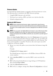
... the Maintenance tab to C5230 platform when selecting Force Update. 4 Click the Upload Firmware button. 5 BMC will not check if the Firmware image belongs to put the device in the BMC firmware package: • Compiled BMC firmware code and data • Web-based user interface, JPEG, and other types of operations. The following data is cancelled. During the process of firmware update, the AC power of firmware update. 1 Browse to successfully update the card's firmware. Example: C:\Updates\V1.0\ The default firmware...
... the Maintenance tab to C5230 platform when selecting Force Update. 4 Click the Upload Firmware button. 5 BMC will not check if the Firmware image belongs to put the device in the BMC firmware package: • Compiled BMC firmware code and data • Web-based user interface, JPEG, and other types of operations. The following data is cancelled. During the process of firmware update, the AC power of firmware update. 1 Browse to successfully update the card's firmware. Example: C:\Updates\V1.0\ The default firmware...

Using the Baseboard Management Controller
Page 32
... open Network Settings page, click Configuration > Network from the main menu. Network Settings Item LAN Interface LAN Settings MAC Address IPv4 Settings Description Lists the LAN interfaces. A sample screenshot of Network Settings page are explained below . The fields of Network Settings Page is shown in the screenshot below . To enable or disable the LAN Settings. This is used to reset the modified changes. Procedure: 1 Choose either of the device. This field displays the MAC Address of the following as your requirement: • Set mode...
... open Network Settings page, click Configuration > Network from the main menu. Network Settings Item LAN Interface LAN Settings MAC Address IPv4 Settings Description Lists the LAN interfaces. A sample screenshot of Network Settings page are explained below . The fields of Network Settings Page is shown in the screenshot below . To enable or disable the LAN Settings. This is used to reset the modified changes. Procedure: 1 Choose either of the device. This field displays the MAC Address of the following as your requirement: • Set mode...

Using the Baseboard Management Controller
Page 33
...; First Number must not be configured to dynamically configure IPv6 address using DHCP (Dynamic Host Configuration Protocol). NOTE: • IP Address made of different address each time. To specify the subnet prefix length for the IPv6 settings. NOTE: When IPv6 Enable and setting DHCP mode, IPv6 address will be configured to 128. It lists the VLAN configuration settings. To specify a static IPv6 address to be assigned of 4 numbers separated...
...; First Number must not be configured to dynamically configure IPv6 address using DHCP (Dynamic Host Configuration Protocol). NOTE: • IP Address made of different address each time. To specify the subnet prefix length for the IPv6 settings. NOTE: When IPv6 Enable and setting DHCP mode, IPv6 address will be configured to 128. It lists the VLAN configuration settings. To specify a static IPv6 address to be assigned of 4 numbers separated...

Using the Baseboard Management Controller
Page 41
... SNMP Status check box to enable SNMP access for the user. NOTE: Password field is mandatory, if Authentication protocol is enabled. 7 Choose the SNMP Access level option for user from Web GUI virtual KVM redirection virtual media Privilege association between IPMI and Web GUI Web GUI Privilege List login BMC from Web GUI, SSH and Telnet configure BMC from Web GUI configure users from Web GUI clear logs from Web GUI execute server power control...
... SNMP Status check box to enable SNMP access for the user. NOTE: Password field is mandatory, if Authentication protocol is enabled. 7 Choose the SNMP Access level option for user from Web GUI virtual KVM redirection virtual media Privilege association between IPMI and Web GUI Web GUI Privilege List login BMC from Web GUI, SSH and Telnet configure BMC from Web GUI configure users from Web GUI clear logs from Web GUI execute server power control...

Using the Baseboard Management Controller
Page 44
... to enable the PEF settings. This is recommended to run-time configurable entries can be made available for the newly configured PEF entry (read-only). Event Filter Tab A PEF implementation is a mandatory field. Remaining entries can be pre-configured for common system failure events, such as being reserved for system use - Event Filter Item PEF ID Filter configuration Event Filter Action Sensor Name Add...
... to enable the PEF settings. This is recommended to run-time configurable entries can be made available for the newly configured PEF entry (read-only). Event Filter Tab A PEF implementation is a mandatory field. Remaining entries can be pre-configured for common system failure events, such as being reserved for system use - Event Filter Item PEF ID Filter configuration Event Filter Action Sensor Name Add...

Getting Started With Your System
Page 5
... the rack posts to lift the system by yourself. Installation and Configuration WARNING: Before performing the following procedure, review and follow the safety instructions that the square peg slides through the use of a tool or lock and key, or other means of IEC 60950-1: 2001 where both these conditions apply: • Access can only be gained by service persons or by users...
... the rack posts to lift the system by yourself. Installation and Configuration WARNING: Before performing the following procedure, review and follow the safety instructions that the square peg slides through the use of a tool or lock and key, or other means of IEC 60950-1: 2001 where both these conditions apply: • Access can only be gained by service persons or by users...

