
Installing 1-GB DIMMs Information Update
Page 3
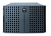
The 16 DIMM sockets on each of the system's two memory boards can accommodate up to 16 GB of synchronous dynamic random-access memory (SDRAM). J16 J1 support.dell.com Dell PowerEdge 8450 Systems - Installing 1-GB DIMMs 1-1 This document provides information for Dell PowerEdge 8450 systems. The system supports one or two memory boards (see Figure 1-1). Dell PowerEdge 8450 systems use PC100 systems registered DIMMs in -line memory modules (DIMMs) and an electromagnetic interference (EMI) shield for installing 1-gigabyte (GB) dual in these 168-pin sockets.
The 16 DIMM sockets on each of the system's two memory boards can accommodate up to 16 GB of synchronous dynamic random-access memory (SDRAM). J16 J1 support.dell.com Dell PowerEdge 8450 Systems - Installing 1-GB DIMMs 1-1 This document provides information for Dell PowerEdge 8450 systems. The system supports one or two memory boards (see Figure 1-1). Dell PowerEdge 8450 systems use PC100 systems registered DIMMs in -line memory modules (DIMMs) and an electromagnetic interference (EMI) shield for installing 1-gigabyte (GB) dual in these 168-pin sockets.
Installing 1-GB DIMMs Information Update
Page 4
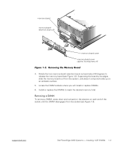
...MB), and 1-GB registered SDRAM DIMMs. Memory upgrade kits can upgrade system memory up to the front of the system chassis, and then pull the cover directly away from the system (see Figure 1-2). 1-2 Dell PowerEdge 8450 Systems - To remove the memory board cover, loosen the four captive ...thumbscrews secur- You can be rated to the following steps. 1. You must configure the system with two memory boards each socket location J1 through "J16" ...
...MB), and 1-GB registered SDRAM DIMMs. Memory upgrade kits can upgrade system memory up to the front of the system chassis, and then pull the cover directly away from the system (see Figure 1-2). 1-2 Dell PowerEdge 8450 Systems - To remove the memory board cover, loosen the four captive ...thumbscrews secur- You can be rated to the following steps. 1. You must configure the system with two memory boards each socket location J1 through "J16" ...
Installing 1-GB DIMMs Information Update
Page 5
Installing 1-GB DIMMs 1-3 memory board memory-board retention levers (2) memory board cover memory-board cover captive thumbscrews (4) 4. Locate the DIMM sockets where you will install or replace DIMMs. 6. To remove a DIMM, press down ... surface. 5. Install or replace the DIMMs to release the memory board (see Figure 1-3). support.dell.com Dell PowerEdge 8450 Systems - Rotate the two memory-board retention levers outward about 90 degrees to reach the desired memory total. Supporting the board by its edges, slide the memory board out from the socket (see Figure 1-2).
Installing 1-GB DIMMs 1-3 memory board memory-board retention levers (2) memory board cover memory-board cover captive thumbscrews (4) 4. Locate the DIMM sockets where you will install or replace DIMMs. 6. To remove a DIMM, press down ... surface. 5. Install or replace the DIMMs to release the memory board (see Figure 1-3). support.dell.com Dell PowerEdge 8450 Systems - Rotate the two memory-board retention levers outward about 90 degrees to reach the desired memory total. Supporting the board by its edges, slide the memory board out from the socket (see Figure 1-2).
Installing 1-GB DIMMs Information Update
Page 8
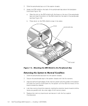
... the peripherals bay to the system chassis with the four captive thumbscrews. 1-6 Dell PowerEdge 8450 Systems - Align the left and right edges of the memory board with the guides in the system and slide the memory board back into the system until the levers are parallel with the brace on... outer edge of the peripherals bay above the backplane board (see Figure 1-6). Lock the memory board into the system chassis. 2. Installing 1-GB DIMMs b. brace peripherals bay EMI shield 1. Replace the memory board cover and secure it into the back of the system chassis. 3. Slide the ...
... the peripherals bay to the system chassis with the four captive thumbscrews. 1-6 Dell PowerEdge 8450 Systems - Align the left and right edges of the memory board with the guides in the system and slide the memory board back into the system until the levers are parallel with the brace on... outer edge of the peripherals bay above the backplane board (see Figure 1-6). Lock the memory board into the system chassis. 2. Installing 1-GB DIMMs b. brace peripherals bay EMI shield 1. Replace the memory board cover and secure it into the back of the system chassis. 3. Slide the ...
Installing 1-GB DIMMs Information Update
Page 9
Reconnect the computer and peripherals to electrical outlets, and turn them on , make sure that all DIMMs and memory boards are installed correctly. 8. Installing 1-GB DIMMs 1-7 6. This completes the installation of the 1-GB DIMM. Run the system memory test in the Dell Diagnostics (see "Running the Dell Diagnostics" in your system's Installation and Troubleshooting Guide). support.dell.com Dell PowerEdge 8450 Systems - NOTE: If memory errors occur after the system is turned on . Replace the front bezel. 7.
Reconnect the computer and peripherals to electrical outlets, and turn them on , make sure that all DIMMs and memory boards are installed correctly. 8. Installing 1-GB DIMMs 1-7 6. This completes the installation of the 1-GB DIMM. Run the system memory test in the Dell Diagnostics (see "Running the Dell Diagnostics" in your system's Installation and Troubleshooting Guide). support.dell.com Dell PowerEdge 8450 Systems - NOTE: If memory errors occur after the system is turned on . Replace the front bezel. 7.

Microprocessor Board Upgrade Guide
Page 5
Removing the Computer Cover 1-4 Removing a Microprocessor Assembly or Terminator Card 1-5 Removing the Front Bezel 1-6 Removing the Memory Board 1-7 Removing the Cooling Fans 1-8 Removing the Fan Bay Housing 1-9 Removing the Control Panel Tray 1-10 Removing the Microprocessor Cage and Microprocessor Boards 1-11 Locating ...
Removing the Computer Cover 1-4 Removing a Microprocessor Assembly or Terminator Card 1-5 Removing the Front Bezel 1-6 Removing the Memory Board 1-7 Removing the Cooling Fans 1-8 Removing the Fan Bay Housing 1-9 Removing the Control Panel Tray 1-10 Removing the Microprocessor Cage and Microprocessor Boards 1-11 Locating ...

Microprocessor Board Upgrade Guide
Page 12
.... Removing the Front Bezel b. Using the key provided with the system, unlock the bezel (step 2 in Figure 1-3). 8. To remove the memory-board cover, loosen the four captive thumbscrews securing the memory-board cover to the front of the system badge on the front bezel to release the catch on the bezel from...
.... Removing the Front Bezel b. Using the key provided with the system, unlock the bezel (step 2 in Figure 1-3). 8. To remove the memory-board cover, loosen the four captive thumbscrews securing the memory-board cover to the front of the system badge on the front bezel to release the catch on the bezel from...

Microprocessor Board Upgrade Guide
Page 13
support.dell.com Microprocessor Board Upgrade Guide 1-7 memory-board cover memory-board retention levers (2) memory-board cover retention screws (4) Figure 1-4. Supporting the board by its edges, slide the memory board out from the system and place it component-side up on an antistatic surface. c. Removing the Memory Board b. Repeat steps a and b if a second memory board is installed. Rotate the two memory-board retention levers outward about 90 degrees to release the memory board (see Figure 1-4).
support.dell.com Microprocessor Board Upgrade Guide 1-7 memory-board cover memory-board retention levers (2) memory-board cover retention screws (4) Figure 1-4. Supporting the board by its edges, slide the memory board out from the system and place it component-side up on an antistatic surface. c. Removing the Memory Board b. Repeat steps a and b if a second memory board is installed. Rotate the two memory-board retention levers outward about 90 degrees to release the memory board (see Figure 1-4).

Microprocessor Board Upgrade Guide
Page 19
Replace the memory board and memory board cover. 9. Microprocessor Board Upgrade Guide 1-13 Locating the Microprocessor Speed Jumpers 5. Replace the fan bay housing and secure it with the three screws. 7. Run the Dell Diagnostics to electrical outlets, and turn them on the Dell Diagnostics, see your system's Installation and Troubleshooting Guide. support.dell.com Figure 1-9. Replace...
Replace the memory board and memory board cover. 9. Microprocessor Board Upgrade Guide 1-13 Locating the Microprocessor Speed Jumpers 5. Replace the fan bay housing and secure it with the three screws. 7. Run the Dell Diagnostics to electrical outlets, and turn them on the Dell Diagnostics, see your system's Installation and Troubleshooting Guide. support.dell.com Figure 1-9. Replace...


