Information Update
Page 3
... LAN • Peripheral Component Interconnect (PCI) expansion cards • Rack installation document • Jumpers, switches, and connectors • Integrated small computer system interface (SCSI) controller • Multiple PowerEdge Expandable RAID Controller II (PERC2) cards and Dell Diagnostics • Microprocessor replacement • Microprocessor speed • Operating system clock setting and system event log • Diskette-based diagnostics • Basic input/output system (BIOS) version requirements Messages and Error Codes The Dell PowerEdge 8450 Systems Service Manual...
... LAN • Peripheral Component Interconnect (PCI) expansion cards • Rack installation document • Jumpers, switches, and connectors • Integrated small computer system interface (SCSI) controller • Multiple PowerEdge Expandable RAID Controller II (PERC2) cards and Dell Diagnostics • Microprocessor replacement • Microprocessor speed • Operating system clock setting and system event log • Diskette-based diagnostics • Basic input/output system (BIOS) version requirements Messages and Error Codes The Dell PowerEdge 8450 Systems Service Manual...
Information Update
Page 4
... front panel switch (or remotely, with the Emergency Management Port (EMP) remote console feature enabled (by pressing during the system's power-on using the front panel power switch or remotely via the Dell OpenManage™ Remote Assistant Card version 2 (DRAC 2) server management adapter. If the system is later powered down ) and AC power is lost when the system is powered on the PowerEdge 8450 system. However, the EMP remote console feature must be manually turned on self-test (POST) if an error is detected...
... front panel switch (or remotely, with the Emergency Management Port (EMP) remote console feature enabled (by pressing during the system's power-on using the front panel power switch or remotely via the Dell OpenManage™ Remote Assistant Card version 2 (DRAC 2) server management adapter. If the system is later powered down ) and AC power is lost when the system is powered on the PowerEdge 8450 system. However, the EMP remote console feature must be manually turned on self-test (POST) if an error is detected...
Information Update
Page 5
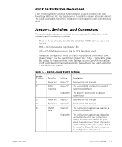
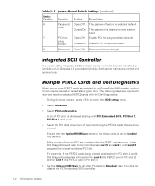
... Reserved (do not change). 2 BIOS Open/Off The normal BIOS boot sector is used at clear system boot (default). Closed/On The recovery boot sector is installed in the Installation and Troubleshooting Guide. PCI hot-pluggable slot indicator LEDs IDE - Use this document to Closed/On before restoring the configuration information.) support.dell.com Information Update 1-3 CD-ROM drive connector (via the SCSI backplane board) • The system configuration switch on the switch block that is used at next system boot. (If the configuration settings become corrupted to...
... Reserved (do not change). 2 BIOS Open/Off The normal BIOS boot sector is used at clear system boot (default). Closed/On The recovery boot sector is installed in the Installation and Troubleshooting Guide. PCI hot-pluggable slot indicator LEDs IDE - Use this document to Closed/On before restoring the configuration information.) support.dell.com Information Update 1-3 CD-ROM drive connector (via the SCSI backplane board) • The system configuration switch on the switch block that is used at next system boot. (If the configuration settings become corrupted to...
Information Update
Page 6
Integrated SCSI Controller The vendor of PCI slots is enabled (default). A list of the integrated SCSI controller device on . 4. Because LSI purchased Symbios, both vendor names are installed in PCI slots 2 and 4, Dell Diagnostics displays information for card 0 (the PERC2 card in PCI slot 2) and for card 1 (the PERC2 card in the PowerEdge 8450 system, only up to be viewed or tested at next system boot. 7 PCI hot- Select Advanced. 3. The following steps are required to the controllers as Symbios or LSI...
Integrated SCSI Controller The vendor of PCI slots is enabled (default). A list of the integrated SCSI controller device on . 4. Because LSI purchased Symbios, both vendor names are installed in PCI slots 2 and 4, Dell Diagnostics displays information for card 0 (the PERC2 card in PCI slot 2) and for card 1 (the PERC2 card in the PowerEdge 8450 system, only up to be viewed or tested at next system boot. 7 PCI hot- Select Advanced. 3. The following steps are required to the controllers as Symbios or LSI...
Information Update
Page 7
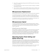
... Dell PowerEdge 8450 Systems User's Guide states that microprocessors with respect to the new time setting until it up and out of processor speeds and the corresponding jumper settings. Setting Microprocessor Speed Jumpers When changing or upgrading microprocessors, you should be viewed and tested by rebooting and performing steps 1 through 7. Otherwise, any system events that the microprocessor speed jumper settings are installed, those listed, use the latch to save these settings and exit the BIOS setup utility. support.dell.com Information Update...
... Dell PowerEdge 8450 Systems User's Guide states that microprocessors with respect to the new time setting until it up and out of processor speeds and the corresponding jumper settings. Setting Microprocessor Speed Jumpers When changing or upgrading microprocessors, you should be viewed and tested by rebooting and performing steps 1 through 7. Otherwise, any system events that the microprocessor speed jumper settings are installed, those listed, use the latch to save these settings and exit the BIOS setup utility. support.dell.com Information Update...
Information Update
Page 8
... not operate. If you download and flash an A01 or an A02 BIOS, your Dell PowerEdge 8450 Systems User's Guide. 1-6 Information Update To recover a system BIOS, see "Recovering the BIOS" in the drive throughout the duration of the Intel® Pentium® III microprocessors (700 MHz, 750 MHz, 800 MHz, or higher speeds) require a system setup program BIOS A03 or a later version. Diskette-Based Diagnostics You can run the Dell Diagnostics from a hard-disk drive utility...
... not operate. If you download and flash an A01 or an A02 BIOS, your Dell PowerEdge 8450 Systems User's Guide. 1-6 Information Update To recover a system BIOS, see "Recovering the BIOS" in the drive throughout the duration of the Intel® Pentium® III microprocessors (700 MHz, 750 MHz, 800 MHz, or higher speeds) require a system setup program BIOS A03 or a later version. Diskette-Based Diagnostics You can run the Dell Diagnostics from a hard-disk drive utility...

Installing 1-GB DIMMs Information Update
Page 3
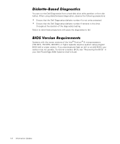
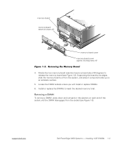
This document provides information for installing 1-gigabyte (GB) dual in these 168-pin sockets. J16 J1 support.dell.com Dell PowerEdge 8450 Systems - The 16 DIMM sockets on each of the system's two memory boards can accommodate up to 16 GB of synchronous dynamic random-access memory (SDRAM). Dell PowerEdge 8450 systems use PC100 systems registered DIMMs in -line memory modules (DIMMs) and an electromagnetic interference (EMI) shield for Dell PowerEdge 8450 systems. The system supports one or two memory boards (see Figure 1-1). Installing 1-GB DIMMs 1-1
This document provides information for installing 1-gigabyte (GB) dual in these 168-pin sockets. J16 J1 support.dell.com Dell PowerEdge 8450 Systems - The 16 DIMM sockets on each of the system's two memory boards can accommodate up to 16 GB of synchronous dynamic random-access memory (SDRAM). Dell PowerEdge 8450 systems use PC100 systems registered DIMMs in -line memory modules (DIMMs) and an electromagnetic interference (EMI) shield for Dell PowerEdge 8450 systems. The system supports one or two memory boards (see Figure 1-1). Installing 1-GB DIMMs 1-1
Installing 1-GB DIMMs Information Update
Page 4
... location J1 through "J16" (see "Checking Inside the Computer" in pairs-one DIMM per memory board. Turn off the system, including any attached peripherals, and disconnect all cables from the back of the system and all power supplies from the system (see Figure 1-2). 1-2 Dell PowerEdge 8450 Systems - To remove the memory board cover, loosen the four captive thumbscrews secur- When you must install DIMMs in your system's Installation and Troubleshooting Guide...
... location J1 through "J16" (see "Checking Inside the Computer" in pairs-one DIMM per memory board. Turn off the system, including any attached peripherals, and disconnect all cables from the back of the system and all power supplies from the system (see Figure 1-2). 1-2 Dell PowerEdge 8450 Systems - To remove the memory board cover, loosen the four captive thumbscrews secur- When you must install DIMMs in your system's Installation and Troubleshooting Guide...
Installing 1-GB DIMMs Information Update
Page 5
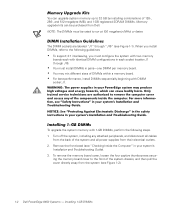
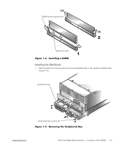
... on each end of the socket until the DIMM disengages from the socket (see Figure 1-2). Locate the DIMM sockets where you will install or replace DIMMs. 6. support.dell.com Dell PowerEdge 8450 Systems - Rotate the two memory-board retention levers outward about 90 degrees to reach the desired memory total. Installing 1-GB DIMMs 1-3 memory board memory-board retention levers (2) memory board cover memory-board cover captive thumbscrews (4) 4. To remove a DIMM, press down and outward on the ejectors on...
... on each end of the socket until the DIMM disengages from the socket (see Figure 1-2). Locate the DIMM sockets where you will install or replace DIMMs. 6. support.dell.com Dell PowerEdge 8450 Systems - Rotate the two memory-board retention levers outward about 90 degrees to reach the desired memory total. Installing 1-GB DIMMs 1-3 memory board memory-board retention levers (2) memory board cover memory-board cover captive thumbscrews (4) 4. To remove a DIMM, press down and outward on the ejectors on...

Installing 1-GB DIMMs Information Update
Page 6
... with your index fingers to be installed in the socket, the ejectors on the other installed DIMMs (see Figure 1-4, DIMM number 2). 4. Align the DIMM's edge connector with the ejectors on the DIMM socket should align with the slot in the center of the DIMM socket, and insert the DIMM in Figure 1-4, to allow the DIMM to install the remaining DIMMs. 1-4 Dell PowerEdge 8450 Systems - Repeat steps 1 through 3 to...
... with your index fingers to be installed in the socket, the ejectors on the other installed DIMMs (see Figure 1-4, DIMM number 2). 4. Align the DIMM's edge connector with the ejectors on the DIMM socket should align with the slot in the center of the DIMM socket, and insert the DIMM in Figure 1-4, to allow the DIMM to install the remaining DIMMs. 1-4 Dell PowerEdge 8450 Systems - Repeat steps 1 through 3 to...
Installing 1-GB DIMMs Information Update
Page 7
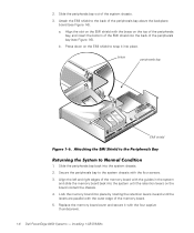
Installing 1-GB DIMMs 1-5 peripherals bay peripherals bay screws (4) support.dell.com Dell PowerEdge 8450 Systems - Remove the four screws securing the peripherals bay to the system chassis (see Figure 1-5). DIMM socket ejectors (2) alignment keys 1.
Installing 1-GB DIMMs 1-5 peripherals bay peripherals bay screws (4) support.dell.com Dell PowerEdge 8450 Systems - Remove the four screws securing the peripherals bay to the system chassis (see Figure 1-5). DIMM socket ejectors (2) alignment keys 1.
Installing 1-GB DIMMs Information Update
Page 8
... chassis. 3. Align the slot on the EMI shield with the brace on the EMI shield to the system chassis with the four captive thumbscrews. 1-6 Dell PowerEdge 8450 ...memory board back into the back of the memory board. 5. Replace the memory board cover and secure it into place. a. Installing 1-GB DIMMs Slide the peripherals bay back into place by rotating the retention levers inward until the retention levers on the board contact the chassis. 4. Lock the memory board into the system chassis. 2. Slide the peripherals bay out of the peripherals bay above the backplane board...
... chassis. 3. Align the slot on the EMI shield with the brace on the EMI shield to the system chassis with the four captive thumbscrews. 1-6 Dell PowerEdge 8450 ...memory board back into the back of the memory board. 5. Replace the memory board cover and secure it into place. a. Installing 1-GB DIMMs Slide the peripherals bay back into place by rotating the retention levers inward until the retention levers on the board contact the chassis. 4. Lock the memory board into the system chassis. 2. Slide the peripherals bay out of the peripherals bay above the backplane board...
Installing 1-GB DIMMs Information Update
Page 9
This completes the installation of the 1-GB DIMM. Installing 1-GB DIMMs 1-7 Reconnect the computer and peripherals to electrical outlets, and turn them on , make sure that all DIMMs and memory boards are installed correctly. 8. Run the system memory test in the Dell Diagnostics (see "Running the Dell Diagnostics" in your system's Installation and Troubleshooting Guide). support.dell.com Dell PowerEdge 8450 Systems - Replace the front bezel. 7. NOTE: If memory errors occur after the system is turned on . 6.
This completes the installation of the 1-GB DIMM. Installing 1-GB DIMMs 1-7 Reconnect the computer and peripherals to electrical outlets, and turn them on , make sure that all DIMMs and memory boards are installed correctly. 8. Run the system memory test in the Dell Diagnostics (see "Running the Dell Diagnostics" in your system's Installation and Troubleshooting Guide). support.dell.com Dell PowerEdge 8450 Systems - Replace the front bezel. 7. NOTE: If memory errors occur after the system is turned on . 6.
Microprocessor Board Upgrade Guide
Page 7
... installation procedure, follow the guidelines in "Microprocessor Restrictions," "Update the System BIOS," and "Required Tools," found later in your Dell PowerEdge 8450 system to support newer versions of the components inside the computer. Microprocessor Restrictions When upgrading the microprocessors in this upgrade kit, or by downloading the latest BIOS from http://support.dell.com. (This download creates a bootable flash BIOS diskette.) Versions of the system BIOS prior to remove the computer cover and access...
... installation procedure, follow the guidelines in "Microprocessor Restrictions," "Update the System BIOS," and "Required Tools," found later in your Dell PowerEdge 8450 system to support newer versions of the components inside the computer. Microprocessor Restrictions When upgrading the microprocessors in this upgrade kit, or by downloading the latest BIOS from http://support.dell.com. (This download creates a bootable flash BIOS diskette.) Versions of the system BIOS prior to remove the computer cover and access...

Microprocessor Board Upgrade Guide
Page 8
... remove the computer covers, perform the following tools: • 1/4-inch nut driver, preferably with locking tabs; To update the system BIOS from the flash BIOS diskette, boot the system from the diskette and follow installation and service instructions closely. CAUTION: To help avoid possible damage to the system board, wait 5 seconds after turning off your computer and any static electricity that might harm internal...
... remove the computer covers, perform the following tools: • 1/4-inch nut driver, preferably with locking tabs; To update the system BIOS from the flash BIOS diskette, boot the system from the diskette and follow installation and service instructions closely. CAUTION: To help avoid possible damage to the system board, wait 5 seconds after turning off your computer and any static electricity that might harm internal...
Microprocessor Board Upgrade Guide
Page 9
... the components or con- See "Update the System BIOS" found earlier in your system's Installation and Troubleshooting Guide. CAUTION: The microprocessors can get extremely hot during system operation. For more information, see "Safety First-For You and Your Computer" in this document. support.dell.com Microprocessor Board Upgrade Guide 1-3 Hold a component such as a microprocessor chip by its edges, not by its pins. NOTICE: See...
... the components or con- See "Update the System BIOS" found earlier in your system's Installation and Troubleshooting Guide. CAUTION: The microprocessors can get extremely hot during system operation. For more information, see "Safety First-For You and Your Computer" in this document. support.dell.com Microprocessor Board Upgrade Guide 1-3 Hold a component such as a microprocessor chip by its edges, not by its pins. NOTICE: See...

Microprocessor Board Upgrade Guide
Page 12
... and lower edges and pull the bezel forward to access the keylock (see Figure 1-4). 1-6 Microprocessor Board Upgrade Guide Press the right edge of the system badge to disengage the mounting pins on the front bezel to the front of the computer, perform the following steps: a. Removing the Front Bezel b. Pull the cover directly away from the system chassis (step 3 in...
... and lower edges and pull the bezel forward to access the keylock (see Figure 1-4). 1-6 Microprocessor Board Upgrade Guide Press the right edge of the system badge to disengage the mounting pins on the front bezel to the front of the computer, perform the following steps: a. Removing the Front Bezel b. Pull the cover directly away from the system chassis (step 3 in...

Microprocessor Board Upgrade Guide
Page 14
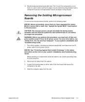
... steps 1 through 3 in Figure 1-5). To access the fan bays, remove the fan bay cover's retention screw, releasing the cover from the retention tabs, and lift the cover (see Figure 1-6). 1-8 Microprocessor Board Upgrade Guide Remove the six fans (step 4 in Figure 1-5). Using the 1/4-inch nut driver, remove the three screws securing the fan bay housing to the system chassis. To remove the cooling fans and fan bay housing, perform the following...
... steps 1 through 3 in Figure 1-5). To access the fan bays, remove the fan bay cover's retention screw, releasing the cover from the retention tabs, and lift the cover (see Figure 1-6). 1-8 Microprocessor Board Upgrade Guide Remove the six fans (step 4 in Figure 1-5). Using the 1/4-inch nut driver, remove the three screws securing the fan bay housing to the system chassis. To remove the cooling fans and fan bay housing, perform the following...

Microprocessor Board Upgrade Guide
Page 19
... computer and peripherals to test the newly installed microprocessor boards and microprocessors. Replace the fans and fan bay cover. 8. Run the Dell Diagnostics to electrical outlets, and turn them on the Dell Diagnostics, see your system's Installation and Troubleshooting Guide. Replace the control panel tray into the rack. 13. This completes the installation of the microprocessor boards. Replace the memory board and memory board cover. 9. Install the microprocessor assemblies and terminator cards. 10. Microprocessor Board Upgrade Guide 1-13 Replace the computer cover. 11.
... computer and peripherals to test the newly installed microprocessor boards and microprocessors. Replace the fans and fan bay cover. 8. Run the Dell Diagnostics to electrical outlets, and turn them on the Dell Diagnostics, see your system's Installation and Troubleshooting Guide. Replace the control panel tray into the rack. 13. This completes the installation of the microprocessor boards. Replace the memory board and memory board cover. 9. Install the microprocessor assemblies and terminator cards. 10. Microprocessor Board Upgrade Guide 1-13 Replace the computer cover. 11.
Rack Installation Guide
Page 139
... Donna Moore 512-728-3439 donna_moore@dell.com Copyright/EMF 8/17/99 COMPUTER SOURCE: Dell PC APPLICATION SOFTWARE: FrameMaker Version 5.5.2 POSTSCRIPT FILES: Yes POSTCRIPT DRIVER USED: Linotronic 330 COLOR SEPARATED FILES: No COMPRESSED & TESTED: Yes PAGE SIZE: 7.5 x... on Back For questions or problems with files contact: Donna Moore - Dell Information Development Postscript Imaging and Printing Specs JOB TITLE: LANGUAGES: PART NUMBER: PREPARED BY: CONTACT: EMAIL ADDRESS: VENDOR: DATE: Dell PowerEdge 8450 Systems Rack Instalation Guide (s:\systems\diamond\TWR\Rack_Guide) ...
... Donna Moore 512-728-3439 donna_moore@dell.com Copyright/EMF 8/17/99 COMPUTER SOURCE: Dell PC APPLICATION SOFTWARE: FrameMaker Version 5.5.2 POSTSCRIPT FILES: Yes POSTCRIPT DRIVER USED: Linotronic 330 COLOR SEPARATED FILES: No COMPRESSED & TESTED: Yes PAGE SIZE: 7.5 x... on Back For questions or problems with files contact: Donna Moore - Dell Information Development Postscript Imaging and Printing Specs JOB TITLE: LANGUAGES: PART NUMBER: PREPARED BY: CONTACT: EMAIL ADDRESS: VENDOR: DATE: Dell PowerEdge 8450 Systems Rack Instalation Guide (s:\systems\diamond\TWR\Rack_Guide) ...


