

Rack Installation Guide
Page 3
... The weight of the rack on the floor. Also refer to tip over , potentially resulting in any other brand of Dell systems and rack kits in bodily injury under certain circumstances. The final installation of rack cabinet has not been approved by yourself.... the full weight of Dell systems and rack kits for use in a rack. NOTE: Dell's servers, storage systems, and appliances are intended to help protect your system's System Information document. If you install the kit in a Dell rack by trained service technicians. WARNING: Installing Dell system components in the rack...
... The weight of the rack on the floor. Also refer to tip over , potentially resulting in any other brand of Dell systems and rack kits in bodily injury under certain circumstances. The final installation of rack cabinet has not been approved by yourself.... the full weight of Dell systems and rack kits for use in a rack. NOTE: Dell's servers, storage systems, and appliances are intended to help protect your system's System Information document. If you install the kit in a Dell rack by trained service technicians. WARNING: Installing Dell system components in the rack...
Rack Installation Guide
Page 4
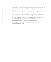
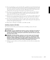
www.dell.com | support.dell.com • Always load the rack from the bottom up, and load the heaviest item in the rack first. • Make sure that the rack ... the branch circuit rating. • Ensure that provides power to components in the rack. • Do not step on or stand on any system/component when servicing other systems/components in a rack. 4 The total rack load should not exceed 80 percent of a rack; the slide rails can pinch your fingers. • After...
www.dell.com | support.dell.com • Always load the rack from the bottom up, and load the heaviest item in the rack first. • Make sure that the rack ... the branch circuit rating. • Ensure that provides power to components in the rack. • Do not step on or stand on any system/component when servicing other systems/components in a rack. 4 The total rack load should not exceed 80 percent of a rack; the slide rails can pinch your fingers. • After...
Rack Installation Guide
Page 5
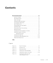
... Installation Tasks 1-4 Removing the Doors From the Rack 1-5 Marking the Rack 1-5 Installing the Slide Assemblies in the Rack 1-7 Installing a System in the Rack 1-10 Installing the Cable Tray and Cable-Management Arm 1-12 Contents 5 Figure 1-4. Rack Kit Contents 1-2 One Rack ...Unit 1-6 Marking the Rack 1-7 Installing the Slide Assemblies 1-8 Installing the System in the Rack 1-9 Installing the System 1-9 Installing the Cable Tray 1-11 Installing the Cable-Management Arm 1-13 Replacing the Rack Doors 1-13 Index Figures Figure ...
... Installation Tasks 1-4 Removing the Doors From the Rack 1-5 Marking the Rack 1-5 Installing the Slide Assemblies in the Rack 1-7 Installing a System in the Rack 1-10 Installing the Cable Tray and Cable-Management Arm 1-12 Contents 5 Figure 1-4. Rack Kit Contents 1-2 One Rack ...Unit 1-6 Marking the Rack 1-7 Installing the Slide Assemblies 1-8 Installing the System in the Rack 1-9 Installing the System 1-9 Installing the Cable Tray 1-11 Installing the Cable-Management Arm 1-13 Replacing the Rack Doors 1-13 Index Figures Figure ...
Rack Installation Guide
Page 7
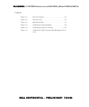
Rack Kit Contents 1-2 One Rack Unit 1-6 Marking the Rack 1-7 Installing the Slide Assemblies 1-8 Installing the System in the Rack 1-10 Installing the Cable Tray and Cable-Management Arm 1-12 DELL CONFIDENTIAL - Figure 1-2. Figure 1-5. Figure 1-6. Figure 1-3. PRELIMINARY 7/24/01 Figure 1-4. FILE LOCATION: S:\SYSTEMS\Bordeaux\rack_inst\RIG\54UMJ_a00\post\54UMJebk0LOF.fm Figures Figure 1-1.
Rack Kit Contents 1-2 One Rack Unit 1-6 Marking the Rack 1-7 Installing the Slide Assemblies 1-8 Installing the System in the Rack 1-10 Installing the Cable Tray and Cable-Management Arm 1-12 DELL CONFIDENTIAL - Figure 1-2. Figure 1-5. Figure 1-6. Figure 1-3. PRELIMINARY 7/24/01 Figure 1-4. FILE LOCATION: S:\SYSTEMS\Bordeaux\rack_inst\RIG\54UMJ_a00\post\54UMJebk0LOF.fm Figures Figure 1-1.
Rack Installation Guide
Page 9
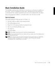
... following items (see Figure 1-1): • One pair of slide assemblies with 32 threads per inch. NOTE: If you should read this installation, you have purchased a Dell rack cabinet with your system, some of the hardware may vary for trained service technicians to be preinstalled in the rack. Rack Installation Guide 1-1 All...
... following items (see Figure 1-1): • One pair of slide assemblies with 32 threads per inch. NOTE: If you should read this installation, you have purchased a Dell rack cabinet with your system, some of the hardware may vary for trained service technicians to be preinstalled in the rack. Rack Installation Guide 1-1 All...
Rack Installation Guide
Page 10
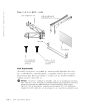
... in the rack. www.dell.com | support.dell.com Figure 1-1. Rack Kit Contents cable-management arm slide assemblies with mounting brackets (2) cable tray rack template 6-32 x 0.25-inch flat-head Phillips screws (2) 6-32 x 0.25-inch hex-head taptite screws (3) Rack Requirements The rack kit is designed for each system that the rack meets... Commission (IEC) 297, and Deutsche Industrie Norm (DIN) 41494. If you will need to be sure that is intended to order a new rack door from Dell before installing your new system in a rack. 1-2 Rack Installation Guide
... in the rack. www.dell.com | support.dell.com Figure 1-1. Rack Kit Contents cable-management arm slide assemblies with mounting brackets (2) cable tray rack template 6-32 x 0.25-inch flat-head Phillips screws (2) 6-32 x 0.25-inch hex-head taptite screws (3) Rack Requirements The rack kit is designed for each system that the rack meets... Commission (IEC) 297, and Deutsche Industrie Norm (DIN) 41494. If you will need to be sure that is intended to order a new rack door from Dell before installing your new system in a rack. 1-2 Rack Installation Guide
Rack Installation Guide
Page 11
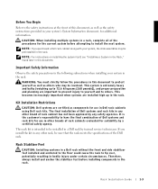
..., potentially resulting in bodily injury under certain circumstances. This rack kit is intended to be preinstalled in the rack. Rack Stabilizer Feet CAUTION: Installing systems in a Dell rack without the front and side stabilizer feet installed and anchored to the floor could cause the rack to others who may be installed in...
..., potentially resulting in bodily injury under certain circumstances. This rack kit is intended to be preinstalled in the rack. Rack Stabilizer Feet CAUTION: Installing systems in a Dell rack without the front and side stabilizer feet installed and anchored to the floor could cause the rack to others who may be installed in...
Rack Installation Guide
Page 12
... The stabilizer feet help prevent the rack from tipping over and cause injury. www.dell.com | support.dell.com CAUTION: After installing systems in a rack, never pull more than one time. The weight of more than one extended system could cause the rack to the documentation provided with the rack cabinet for use in...
... The stabilizer feet help prevent the rack from tipping over and cause injury. www.dell.com | support.dell.com CAUTION: After installing systems in a rack, never pull more than one time. The weight of more than one extended system could cause the rack to the documentation provided with the rack cabinet for use in...
Rack Installation Guide
Page 13
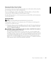
..., as in the Dell PowerEdge 4210 Rack Installation Guide. For more information on configuring a Dell rack, refer to the Dell Rack Advisor software available on removing rack doors. Rack Installation Guide 1-5 For other Dell rack cabinets, see the documentation provided with the rack for each system you install in the... rack. 1 Determine where you are marked either by small indentations in 1-U (4.44 cm or 1.75-inch) increments (see the procedures contained in the PowerEdge 4210 rack, by Dell, skip this section. Marking the ...
..., as in the Dell PowerEdge 4210 Rack Installation Guide. For more information on configuring a Dell rack, refer to the Dell Rack Advisor software available on removing rack doors. Rack Installation Guide 1-5 For other Dell rack cabinets, see the documentation provided with the rack for each system you install in the... rack. 1 Determine where you are marked either by small indentations in 1-U (4.44 cm or 1.75-inch) increments (see the procedures contained in the PowerEdge 4210 rack, by Dell, skip this section. Marking the ...
Rack Installation Guide
Page 14
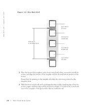
www.dell.com | support.dell.com Figure 1-2. One Rack Unit 4.44 cm or 1.75 inches (1 U) 12.7 mm or 0.5 inch 15.9 mm or 0.625 inch 15.9 mm or 0.625 inch 12.7 ... template identifies the side facing outward as the template front. 3 Mark the front vertical rails with a felt-tipped marker or place masking tape where the system's upper and lower edges will be located (see Figure 1-3) and on the vertical rails next to install the...
www.dell.com | support.dell.com Figure 1-2. One Rack Unit 4.44 cm or 1.75 inches (1 U) 12.7 mm or 0.5 inch 15.9 mm or 0.625 inch 15.9 mm or 0.625 inch 12.7 ... template identifies the side facing outward as the template front. 3 Mark the front vertical rails with a felt-tipped marker or place masking tape where the system's upper and lower edges will be located (see Figure 1-3) and on the vertical rails next to install the...
Rack Installation Guide
Page 17
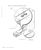
... Position the slide assembly mounting flange against the inner side of the rack's front vertical rail so that follow provide instructions for installing a system in the rack. A mechanical lifting platform or similar equipment of the rack at a time. The mounting hooks move down, and the ...require a sturdy, elevated platform to increase the slide assembly's length until they lock in the fully extended position (see Figure 1-5). Installing a System in the Rack The subsections that the uppermost hook is in the topmost hole and just below the upper mounting hook. 6 Repeat steps ...
... Position the slide assembly mounting flange against the inner side of the rack's front vertical rail so that follow provide instructions for installing a system in the rack. A mechanical lifting platform or similar equipment of the rack at a time. The mounting hooks move down, and the ...require a sturdy, elevated platform to increase the slide assembly's length until they lock in the fully extended position (see Figure 1-5). Installing a System in the Rack The subsections that the uppermost hook is in the topmost hole and just below the upper mounting hook. 6 Repeat steps ...
Rack Installation Guide
Page 18
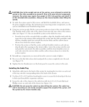
www.dell.com | support.dell.com Figure 1-5. Installing the System in the Rack interior slides (2) shoulder-head studs slide release latch (2) yellow chassis release lever (2) 1-10 Rack Installation Guide
www.dell.com | support.dell.com Figure 1-5. Installing the System in the Rack interior slides (2) shoulder-head studs slide release latch (2) yellow chassis release lever (2) 1-10 Rack Installation Guide
Rack Installation Guide
Page 19
... and label the hard-disk drives, and remove the power supplies and fans. Even with the inner slots in the interior slides and push the system into the slide assemblies until the front shoulder screw on each end of the tray onto the corresponding tabs in the back of the chassis... tray with two 6-32 x 0.25-inch flat-head Phillips screws on the extended slide assemblies. CAUTION: Do not grasp the cable tray when lifting the system. For instructions on each side of the chassis (see Figure 1-5). The cable tray and its mounting are directly above the openings in the interior slides...
... and label the hard-disk drives, and remove the power supplies and fans. Even with the inner slots in the interior slides and push the system into the slide assemblies until the front shoulder screw on each end of the tray onto the corresponding tabs in the back of the chassis... tray with two 6-32 x 0.25-inch flat-head Phillips screws on the extended slide assemblies. CAUTION: Do not grasp the cable tray when lifting the system. For instructions on each side of the chassis (see Figure 1-5). The cable tray and its mounting are directly above the openings in the interior slides...
Rack Installation Guide
Page 21
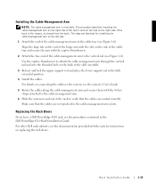
...rod and place the lower support rod in the cable-management arm joints. For other Dell rack cabinets, see the documentation provided with the Velcro straps attached to the cable tray (see the system's User's Guide. 5 Route the cables along the cable-management arm and secure ...right side of the back of the cable-management arm to the cable-management arm. 6 Slide the system in the Dell PowerEdge 4210 Rack Installation Guide. Replacing the Rack Doors If you have a Dell PowerEdge 4210 rack, see Figure 1-6). Installing the Cable-Management Arm NOTE: The cable management arm is reversible...
...rod and place the lower support rod in the cable-management arm joints. For other Dell rack cabinets, see the documentation provided with the Velcro straps attached to the cable tray (see the system's User's Guide. 5 Route the cables along the cable-management arm and secure ...right side of the back of the cable-management arm to the cable-management arm. 6 Slide the system in the Dell PowerEdge 4210 Rack Installation Guide. Replacing the Rack Doors If you have a Dell PowerEdge 4210 rack, see Figure 1-6). Installing the Cable-Management Arm NOTE: The cable management arm is reversible...

Rack Installation Guide
Page 23
... cable tray installing, 1-11 contents illustrated, 1-2 contents of kit, 1-1 D doors removing, 1-5 replacing, 1-13 I installation restrictions, 1-3 installing cable management arm, 1-12 cable tray, 1-12 slide assemblies, 1-7 system in rack, 1-9, 1-10 installing slide assemblies, 1-7 K kit contents, 1-1 list of, 1-1 M marking the rack, 1-5 R rack requirements, 1-2 stabilizer feet, 1-3 rack kit contents list of, 1-1 rack requirements, 1-2 rack...
... cable tray installing, 1-11 contents illustrated, 1-2 contents of kit, 1-1 D doors removing, 1-5 replacing, 1-13 I installation restrictions, 1-3 installing cable management arm, 1-12 cable tray, 1-12 slide assemblies, 1-7 system in rack, 1-9, 1-10 installing slide assemblies, 1-7 K kit contents, 1-1 list of, 1-1 M marking the rack, 1-5 R rack requirements, 1-2 stabilizer feet, 1-3 rack kit contents list of, 1-1 rack requirements, 1-2 rack...


