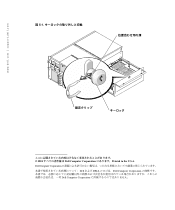
Removing and Replacing the Keylock
Page 10
Dell Computer Corporation 5-1. © 2001 Dell Computer Corporation Dell Computer Corporation Dell DELL Dell Computer Corporation Printed in the U.S.A.
Dell Computer Corporation 5-1. © 2001 Dell Computer Corporation Dell Computer Corporation Dell DELL Dell Computer Corporation Printed in the U.S.A.
Rack Installation Guide
Page 2
... damage to change without the written permission of data and tells you make better use of Dell Computer Corporation. A00 Reproduction in any proprietary interest in severe injury. Other trademarks and trade names may be used in this text: Dell, the DELL logo, and PowerEdge are trademarks of your computer. Information in this document is subject to hardware or loss...
... damage to change without the written permission of data and tells you make better use of Dell Computer Corporation. A00 Reproduction in any proprietary interest in severe injury. Other trademarks and trade names may be used in this text: Dell, the DELL logo, and PowerEdge are trademarks of your computer. Information in this document is subject to hardware or loss...

Rack Installation Guide
Page 3
... installing components in the rack. Also refer to various peripherals or supporting hardware. WARNING: After installing system/components in Dell's rack cabinet using the Dell customer rack kit. Due to the height and weight of the rack, Dell recommends a minimum of rack cabinet has not been approved by trained service technicians. Safety Instructions Safety Caution and Warnings Use the following precautions for rack stability and safety. The final installation of Dell systems and rack kits...
... installing components in the rack. Also refer to various peripherals or supporting hardware. WARNING: After installing system/components in Dell's rack cabinet using the Dell customer rack kit. Due to the height and weight of the rack, Dell recommends a minimum of rack cabinet has not been approved by trained service technicians. Safety Instructions Safety Caution and Warnings Use the following precautions for rack stability and safety. The final installation of Dell systems and rack kits...
Rack Installation Guide
Page 4
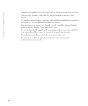
... of a rack; www.dell.com | support.dell.com • Always load the rack from the rack. • Use caution when pressing the component rail release latches and sliding a component into the rack. • Do not overload the AC supply branch circuit that provides power to components in the rack. • Do not step on or stand on any system/component when servicing other...
... of a rack; www.dell.com | support.dell.com • Always load the rack from the rack. • Use caution when pressing the component rail release latches and sliding a component into the rack. • Do not overload the AC supply branch circuit that provides power to components in the rack. • Do not step on or stand on any system/component when servicing other...
Rack Installation Guide
Page 5
... 1-3 Recommended Tools and Supplies 1-4 Installation Tasks 1-4 Removing the Doors From the Rack 1-5 Marking the Rack 1-5 Installing the Slide Assemblies in the Rack 1-7 Installing a System in the Rack 1-10 Installing the Cable Tray and Cable-Management Arm 1-12 Contents 5 Figure 1-3. Figure 1-5. Rack Kit Contents 1-2 One Rack Unit 1-6 Marking the Rack 1-7 Installing the Slide Assemblies 1-8 Installing the System in the Rack 1-9 Installing the System 1-9 Installing the Cable Tray 1-11 Installing the Cable-Management Arm 1-13 Replacing the Rack Doors 1-13...
... 1-3 Recommended Tools and Supplies 1-4 Installation Tasks 1-4 Removing the Doors From the Rack 1-5 Marking the Rack 1-5 Installing the Slide Assemblies in the Rack 1-7 Installing a System in the Rack 1-10 Installing the Cable Tray and Cable-Management Arm 1-12 Contents 5 Figure 1-3. Figure 1-5. Rack Kit Contents 1-2 One Rack Unit 1-6 Marking the Rack 1-7 Installing the Slide Assemblies 1-8 Installing the System in the Rack 1-9 Installing the System 1-9 Installing the Cable Tray 1-11 Installing the Cable-Management Arm 1-13 Replacing the Rack Doors 1-13...
Rack Installation Guide
Page 7
Figure 1-2. Figure 1-6. PRELIMINARY 7/24/01 Figure 1-3. FILE LOCATION: S:\SYSTEMS\Bordeaux\rack_inst\RIG\54UMJ_a00\post\54UMJebk0LOF.fm Figures Figure 1-1. Figure 1-4. Figure 1-5. Rack Kit Contents 1-2 One Rack Unit 1-6 Marking the Rack 1-7 Installing the Slide Assemblies 1-8 Installing the System in the Rack 1-10 Installing the Cable Tray and Cable-Management Arm 1-12 DELL CONFIDENTIAL -
Figure 1-2. Figure 1-6. PRELIMINARY 7/24/01 Figure 1-3. FILE LOCATION: S:\SYSTEMS\Bordeaux\rack_inst\RIG\54UMJ_a00\post\54UMJebk0LOF.fm Figures Figure 1-1. Figure 1-4. Figure 1-5. Rack Kit Contents 1-2 One Rack Unit 1-6 Marking the Rack 1-7 Installing the Slide Assemblies 1-8 Installing the System in the Rack 1-10 Installing the Cable Tray and Cable-Management Arm 1-12 DELL CONFIDENTIAL -
Rack Installation Guide
Page 9
... cable tray • One rack template NOTE: The number of parts may vary for rack kits preinstalled by size and the number of the hardware may be installed in the rack cabinet. NOTE: The nonmetric screws described in illustrations and procedural steps are accommodated. For example, a #10 Phillips-head screw with 32 threads per inch. Rack Installation Guide This installation guide provides instructions for trained service technicians...
... cable tray • One rack template NOTE: The number of parts may vary for rack kits preinstalled by size and the number of the hardware may be installed in the rack cabinet. NOTE: The nonmetric screws described in illustrations and procedural steps are accommodated. For example, a #10 Phillips-head screw with 32 threads per inch. Rack Installation Guide This installation guide provides instructions for trained service technicians...
Rack Installation Guide
Page 10
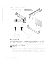
NOTICE: This rack kit is installed in a rack. 1-2 Rack Installation Guide If you will need to be sure that the back door does not contain flush-mounted glass. If you have a Dell rack cabinet with an extended-depth back door. One rack kit is required for use in a Dell rack by trained service technicians. www.dell.com | support.dell.com Figure 1-1. If it does, you install the kit in the rack. Rack Kit Contents cable-management arm slide...
NOTICE: This rack kit is installed in a rack. 1-2 Rack Installation Guide If you will need to be sure that the back door does not contain flush-mounted glass. If you have a Dell rack cabinet with an extended-depth back door. One rack kit is required for use in a Dell rack by trained service technicians. www.dell.com | support.dell.com Figure 1-1. If it does, you install the kit in the rack. Rack Kit Contents cable-management arm slide...
Rack Installation Guide
Page 11
...: For instructions on installing the system itself, see "Installing a System in the Rack," found later in the rack. WARNING: You must strictly follow the procedures in this document to have the final combination of Dell systems and rack kits for use in Dell rack cabinets using Dell rack kits. It is the customer's responsibility to protect yourself as well as others . Rack Installation Guide 1-3 CAUTION: When installing multiple systems in a rack, complete...
...: For instructions on installing the system itself, see "Installing a System in the Rack," found later in the rack. WARNING: You must strictly follow the procedures in this document to have the final combination of Dell systems and rack kits for use in Dell rack cabinets using Dell rack kits. It is the customer's responsibility to protect yourself as well as others . Rack Installation Guide 1-3 CAUTION: When installing multiple systems in a rack, complete...
Rack Installation Guide
Page 12
... system could cause the rack to the documentation provided with the slide assemblies fully extended. Refer to tip over when a system or other component is pulled out of the rack on installing and anchoring the stabilizer feet. www.dell.com | support.dell.com CAUTION: After installing systems in the rack • Installing the cable tray • Installing the cable management arm • Replacing the rack doors 1-4 Rack Installation Guide
... system could cause the rack to the documentation provided with the slide assemblies fully extended. Refer to tip over when a system or other component is pulled out of the rack on installing and anchoring the stabilizer feet. www.dell.com | support.dell.com CAUTION: After installing systems in the rack • Installing the cable tray • Installing the cable management arm • Replacing the rack doors 1-4 Rack Installation Guide
Rack Installation Guide
Page 13
...numbered 1-U markings on configuring a Dell rack, refer to the doors while installing the kit. CAUTION: If you are installing more than one slide assembly and the top of the next. If you must remove the doors from the rack to provide access to the interior of the rack and to prevent damage to the Dell Rack Advisor software available on removing rack doors. In the Dell rack, the rails... in the Dell PowerEdge 4210 Rack Installation Guide. You must allow 7 units (U), or 31.1 centimeters (cm [12.25 inches]) of vertical space for instructions on the Dell Web site at http://www...
...numbered 1-U markings on configuring a Dell rack, refer to the doors while installing the kit. CAUTION: If you are installing more than one slide assembly and the top of the next. If you must remove the doors from the rack to provide access to the interior of the rack and to prevent damage to the Dell Rack Advisor software available on removing rack doors. In the Dell rack, the rails... in the Dell PowerEdge 4210 Rack Installation Guide. You must allow 7 units (U), or 31.1 centimeters (cm [12.25 inches]) of vertical space for instructions on the Dell Web site at http://www...
Rack Installation Guide
Page 14
... vertical rails with a felt-tipped marker or place masking tape where the system's upper and lower edges will be located (see Figure 1-3) and on the vertical rails next to install the system, and align the bottom of the template with the desired bottom position of the system. Ensure that are marked in red. 1-6 Rack Installation Guide www.dell.com | support.dell...
... vertical rails with a felt-tipped marker or place masking tape where the system's upper and lower edges will be located (see Figure 1-3) and on the vertical rails next to install the system, and align the bottom of the template with the desired bottom position of the system. Ensure that are marked in red. 1-6 Rack Installation Guide www.dell.com | support.dell...
Rack Installation Guide
Page 15
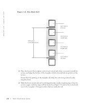
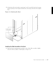
Marking the Rack 7U (31.1 cm or 12.25 inches) Installing the Slide Assemblies in the Rack 1 Slide the back mounting flange toward the center of the rack cabinet, repeat steps 2 and 3 to slightly reduce the slide assembly's overall length (see Figure 1-4). 4 At the back of the slide assembly to mark the back rail, ensuring that the printing on the template identifies the side facing outward as the template back. Figure 1-3. Rack Installation Guide 1-7
Marking the Rack 7U (31.1 cm or 12.25 inches) Installing the Slide Assemblies in the Rack 1 Slide the back mounting flange toward the center of the rack cabinet, repeat steps 2 and 3 to slightly reduce the slide assembly's overall length (see Figure 1-4). 4 At the back of the slide assembly to mark the back rail, ensuring that the printing on the template identifies the side facing outward as the template back. Figure 1-3. Rack Installation Guide 1-7
Rack Installation Guide
Page 16
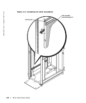
Installing the Slide Assemblies latching tab slide assembly mounting flange (2) 1-8 Rack Installation Guide www.dell.com | support.dell.com Figure 1-4.
Installing the Slide Assemblies latching tab slide assembly mounting flange (2) 1-8 Rack Installation Guide www.dell.com | support.dell.com Figure 1-4.
Rack Installation Guide
Page 17
... proper capacity may require a sturdy, elevated platform to four people and may also be useful. A mechanical lifting platform or similar equipment of the first system in the rack. Rack Installation Guide 1-9 Position the slide assembly mounting flange against the inner side of the rack's front vertical rail so that follow provide instructions for installing a system in the rack before starting the second. The...
... proper capacity may require a sturdy, elevated platform to four people and may also be useful. A mechanical lifting platform or similar equipment of the first system in the rack. Rack Installation Guide 1-9 Position the slide assembly mounting flange against the inner side of the rack's front vertical rail so that follow provide instructions for installing a system in the rack before starting the second. The...
Rack Installation Guide
Page 18
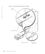
www.dell.com | support.dell.com Figure 1-5. Installing the System in the Rack interior slides (2) shoulder-head studs slide release latch (2) yellow chassis release lever (2) 1-10 Rack Installation Guide
www.dell.com | support.dell.com Figure 1-5. Installing the System in the Rack interior slides (2) shoulder-head studs slide release latch (2) yellow chassis release lever (2) 1-10 Rack Installation Guide
Rack Installation Guide
Page 19
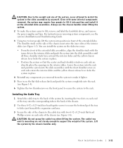
... the cable tray to the back of the system by inserting the two slots on each side enters the interior slides and the yellow chassis release lever locks the system in place. 4 Reinstall any components you removed from the system to make the system easier to lift, remove and label the hard-disk drives, and remove the power supplies and fans. Rack Installation Guide 1-11...
... the cable tray to the back of the system by inserting the two slots on each side enters the interior slides and the yellow chassis release lever locks the system in place. 4 Reinstall any components you removed from the system to make the system easier to lift, remove and label the hard-disk drives, and remove the power supplies and fans. Rack Installation Guide 1-11...

Rack Installation Guide
Page 20
www.dell.com | support.dell.com Figure 1-6. Installing the Cable Tray and Cable-Management Arm cable-management arm 1-12 Rack Installation Guide Velcro strips large tab 6-32 x 0.25-inch hex-head taptite Phillips screws (3) slotted tabs cable tray 6-32 x 0.25-inch flat-head Phillips screws (2)
www.dell.com | support.dell.com Figure 1-6. Installing the Cable Tray and Cable-Management Arm cable-management arm 1-12 Rack Installation Guide Velcro strips large tab 6-32 x 0.25-inch hex-head taptite Phillips screws (3) slotted tabs cable tray 6-32 x 0.25-inch flat-head Phillips screws (2)
Rack Installation Guide
Page 21
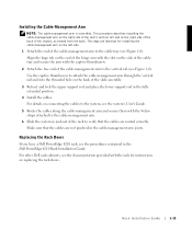
Installing the Cable-Management Arm NOTE: The cable management arm is reversible. Make sure that the cables are not pinched in and out of the chassis, as viewed from the back. The steps are identical for instructions on replacing the rack doors. Rack Installation Guide 1-13 Align the large tab on the end of the hinge arm with the slot on connecting the cables to verify that the...
Installing the Cable-Management Arm NOTE: The cable management arm is reversible. Make sure that the cables are not pinched in and out of the chassis, as viewed from the back. The steps are identical for instructions on replacing the rack doors. Rack Installation Guide 1-13 Align the large tab on the end of the hinge arm with the slot on connecting the cables to verify that the...

Rack Installation Guide
Page 23
Index B before you begin, 1-3 C cabinet doors, 1-5 cable management arm installing, 1-12 cable tray installing, 1-11 contents illustrated, 1-2 contents of kit, 1-1 D doors removing, 1-5 replacing, 1-13 I installation restrictions, 1-3 installing cable management arm, 1-12 cable tray, 1-12 slide assemblies, 1-7 system in rack, 1-9, 1-10 installing slide assemblies, 1-7 K kit contents, 1-1 list of, 1-1 M marking the rack, 1-5 R rack requirements, 1-2 stabilizer feet, 1-3 rack kit contents list of, 1-1 rack requirements, 1-2 rack stabilizer feet, 1-3 restrictions, 1-3 S safety information, 1-3...
Index B before you begin, 1-3 C cabinet doors, 1-5 cable management arm installing, 1-12 cable tray installing, 1-11 contents illustrated, 1-2 contents of kit, 1-1 D doors removing, 1-5 replacing, 1-13 I installation restrictions, 1-3 installing cable management arm, 1-12 cable tray, 1-12 slide assemblies, 1-7 system in rack, 1-9, 1-10 installing slide assemblies, 1-7 K kit contents, 1-1 list of, 1-1 M marking the rack, 1-5 R rack requirements, 1-2 stabilizer feet, 1-3 rack kit contents list of, 1-1 rack requirements, 1-2 rack stabilizer feet, 1-3 restrictions, 1-3 S safety information, 1-3...

