
Service Manual
Page 3
... Hard-Disk Drives 1-8 SCSI Configuration Guidelines 1-9 SCSI ID Numbers 1-9 Device Termination 1-9 SCSI Cable 1-10 System Unit 1-10 System Power Supply 1-10 Pin Assignments for the DC Power Connectors (Redundant and Nonredundant Systems 1-11 DC Power Distribution 1-15 System Board Layout 1-16 System Board Jumpers and Switches 1-17 Microprocessor Module Jumpers 1-20 SCSI Backplane Board...
... Hard-Disk Drives 1-8 SCSI Configuration Guidelines 1-9 SCSI ID Numbers 1-9 Device Termination 1-9 SCSI Cable 1-10 System Unit 1-10 System Power Supply 1-10 Pin Assignments for the DC Power Connectors (Redundant and Nonredundant Systems 1-11 DC Power Distribution 1-15 System Board Layout 1-16 System Board Jumpers and Switches 1-17 Microprocessor Module Jumpers 1-20 SCSI Backplane Board...
Service Manual
Page 4
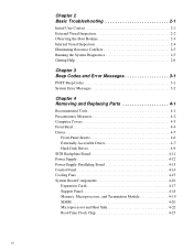
... Replacing Parts 4-1 Recommended Tools 4-1 Precautionary Measures 4-2 Computer Covers 4-3 Front Bezel 4-4 Drives 4-5 Front-Panel Inserts 4-6 Externally Accessible Drives 4-7 Hard-Disk Drives 4-9 SCSI Backplane Board 4-11 Power Supply 4-12 Power-Supply Paralleling Board 4-13 Control Panel 4-14 Cooling Fans 4-15 System Board Components 4-16 Expansion Cards 4-17 Support Panel 4-18 Memory, Microprocessor, and Termination Module 4-19...
... Replacing Parts 4-1 Recommended Tools 4-1 Precautionary Measures 4-2 Computer Covers 4-3 Front Bezel 4-4 Drives 4-5 Front-Panel Inserts 4-6 Externally Accessible Drives 4-7 Hard-Disk Drives 4-9 SCSI Backplane Board 4-11 Power Supply 4-12 Power-Supply Paralleling Board 4-13 Control Panel 4-14 Cooling Fans 4-15 System Board Components 4-16 Expansion Cards 4-17 Support Panel 4-18 Memory, Microprocessor, and Termination Module 4-19...

Service Manual
Page 5
... Figure 1-14. Front/Left Internal View 1-4 Figure 1-4. Power Supply Connectors 1-11 Figure 1-8. DC Power Connector PWR1 1-12 Figure 1-9. System Board Components 1-16 Figure 1-15. Back Panel Features 1-6 Figure 1-6. DC Power Connector PWR2 and PWR3 1-12 Figure 1-10. System Board Jumpers and Switches ...1-13 Figure 1-11. SCSI Backplane Board 1-21 vii Memory Module and SIMM Sockets 1-7 Figure 1-7. DC Power Connector PWRFD (FD1-FD4 1-13 Figure 1-12. Power-Supply Paralleling Board Connectors 1-14 Figure 1-13. System Board 4-27 Battery on Control Panel 4-28 Appendix A ...
... Figure 1-14. Front/Left Internal View 1-4 Figure 1-4. Power Supply Connectors 1-11 Figure 1-8. DC Power Connector PWR1 1-12 Figure 1-9. System Board Components 1-16 Figure 1-15. Back Panel Features 1-6 Figure 1-6. DC Power Connector PWR2 and PWR3 1-12 Figure 1-10. System Board Jumpers and Switches ...1-13 Figure 1-11. SCSI Backplane Board 1-21 vii Memory Module and SIMM Sockets 1-7 Figure 1-7. DC Power Connector PWRFD (FD1-FD4 1-13 Figure 1-12. Power-Supply Paralleling Board Connectors 1-14 Figure 1-13. System Board 4-27 Battery on Control Panel 4-28 Appendix A ...

Service Manual
Page 6
...Figure 4-26. Battery Removal 4-28 Figure A-1. Security Menu A-12 Figure A-8. Exit Menu A-14 viii Computer Covers Removal 4-3 Figure 4-2. Power-Supply Paralleling Board Removal 4-13 Figure 4-13. Memory Module and SIMM Sockets 4-20 Figure 4-20. System Board Removal 4-27 Figure 4-28...Front Bezel Removal 4-4 Figure 4-4. Control Panel Removal 4-14 Figure 4-14. RTC Chip Removal 4-25 Figure 4-27. Main Menu A-3 Figure A-2. Power Supply Removal 4-12 Figure 4-12. Cooling Fan Removal 4-15 Figure 4-15. SIMM Removal 4-20 Figure 4-21. Boot Options Submenu A-5 Figure A-3....
...Figure 4-26. Battery Removal 4-28 Figure A-1. Security Menu A-12 Figure A-8. Exit Menu A-14 viii Computer Covers Removal 4-3 Figure 4-2. Power-Supply Paralleling Board Removal 4-13 Figure 4-13. Memory Module and SIMM Sockets 4-20 Figure 4-20. System Board Removal 4-27 Figure 4-28...Front Bezel Removal 4-4 Figure 4-4. Control Panel Removal 4-14 Figure 4-14. RTC Chip Removal 4-25 Figure 4-27. Main Menu A-3 Figure A-2. Power Supply Removal 4-12 Figure 4-12. Cooling Fan Removal 4-15 Figure 4-15. SIMM Removal 4-20 Figure 4-21. Boot Options Submenu A-5 Figure A-3....
Service Manual
Page 9
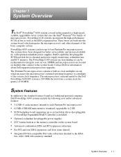
... manual is a high-speed, scalable, upgradable server system that connect to the system board. Contact Dell for the Dell PowerEdge 6100/200 system is installed) • Optional, redundant hot-pluggable power supplies • ECC feature built in a traditional personal computer, Dell PowerEdge 6100 systems include the following new and/or advanced features: • 512 KB of cache memory internal...
... manual is a high-speed, scalable, upgradable server system that connect to the system board. Contact Dell for the Dell PowerEdge 6100/200 system is installed) • Optional, redundant hot-pluggable power supplies • ECC feature built in a traditional personal computer, Dell PowerEdge 6100 systems include the following new and/or advanced features: • 512 KB of cache memory internal...

Service Manual
Page 13
external drive bay (4) Ultra/Wide SCSI interface cable internal drive bay (6) SCSI backplane board closeout panel or optional power supply power supply SMB connector Figure 1-4. Back/Right Internal View SCSI connector slots System Overview 1-5
external drive bay (4) Ultra/Wide SCSI interface cable internal drive bay (6) SCSI backplane board closeout panel or optional power supply power supply SMB connector Figure 1-4. Back/Right Internal View SCSI connector slots System Overview 1-5
Service Manual
Page 14
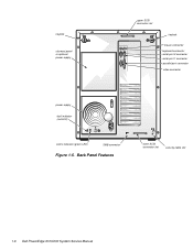
keylock closeout panel or optional power supply upper SCSI connector slot keylock mouse connector keyboard connector serial port 2 connector serial port 1 connector parallel port connector video connector power supply fault indicator (red LED) online indicator (green LED) SMB connector Figure 1-5. Back Panel Features lower SCSI connector slot security cable slot 1-6 Dell PowerEdge 6100/200 System Service Manual
keylock closeout panel or optional power supply upper SCSI connector slot keylock mouse connector keyboard connector serial port 2 connector serial port 1 connector parallel port connector video connector power supply fault indicator (red LED) online indicator (green LED) SMB connector Figure 1-5. Back Panel Features lower SCSI connector slot security cable slot 1-6 Dell PowerEdge 6100/200 System Service Manual
Service Manual
Page 18
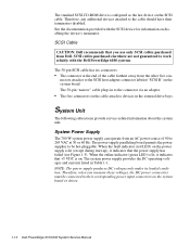
... the system board or drives. 1-10 Dell PowerEdge 6100/200 System Service Manual SCSI cables purchased elsewhere are not guaranteed to the cable should have their corresponding power input connectors on . nectors attaches to devices in Table 1-1. NOTE: The power supply produces DC voltages only under its loaded ...information on the SCSI cable. See the documentation provided with the Dell PowerEdge 6100 systems. The 50-pin SCSI cable has six connectors: • The connector at 50 or 60 Hz. The system power supply provides the DC operating voltages and currents listed in the external ...
... the system board or drives. 1-10 Dell PowerEdge 6100/200 System Service Manual SCSI cables purchased elsewhere are not guaranteed to the cable should have their corresponding power input connectors on . nectors attaches to devices in Table 1-1. NOTE: The power supply produces DC voltages only under its loaded ...information on the SCSI cable. See the documentation provided with the Dell PowerEdge 6100 systems. The 50-pin SCSI cable has six connectors: • The connector at 50 or 60 Hz. The system power supply provides the DC operating voltages and currents listed in the external ...

Service Manual
Page 19
...Dell recommends that the power supply be placed in the bottom receptacle (power supply #2) for the DC Power Connectors (Redundant and Nonredundant Systems) The system may have one (nonredundant) or two (redundant) power supplies. P2 P1 P5 P4 P3 Figure 1-7. Pin Assignments for better weight distribution. For a redundant power supply... system, the only requirement is to +5.36 VDC 0.25 A 1 Maximum continuous DC output power shall not exceed 500 W. 2 VFP (volts flea power) - sometimes called "standby power." . See Figures 1-8 through...
...Dell recommends that the power supply be placed in the bottom receptacle (power supply #2) for the DC Power Connectors (Redundant and Nonredundant Systems) The system may have one (nonredundant) or two (redundant) power supplies. P2 P1 P5 P4 P3 Figure 1-7. Pin Assignments for better weight distribution. For a redundant power supply... system, the only requirement is to +5.36 VDC 0.25 A 1 Maximum continuous DC output power shall not exceed 500 W. 2 VFP (volts flea power) - sometimes called "standby power." . See Figures 1-8 through...

Service Manual
Page 21
... (red) common (black) common (black) +12 VDC (yellow) 1 Wires 1 through 4 are connected to FD1 and FD2. 2 Wires 5 through 8 are connected to turn on/off each power supply. common (black) common (black) common (black) common (black) common (black) common (black) common (black) 8 9 10 11 12 13 14 PWRSCSI (DDBP) 1 23 4 5 6 7 +12 VDC (yellow...
... (red) common (black) common (black) +12 VDC (yellow) 1 Wires 1 through 4 are connected to FD1 and FD2. 2 Wires 5 through 8 are connected to turn on/off each power supply. common (black) common (black) common (black) common (black) common (black) common (black) common (black) 8 9 10 11 12 13 14 PWRSCSI (DDBP) 1 23 4 5 6 7 +12 VDC (yellow...
Service Manual
Page 22
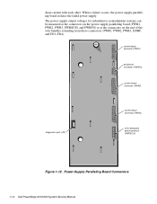
... port (J32) system board connector (PWR3) SCSI backplane board connector (PWRSCSI) Figure 1-12. Power-Supply Paralleling Board Connectors 1-14 Dell PowerEdge 6100/200 System Service Manual When a failure occurs, the power-supply paralleling board isolates the failed power supply. share current with each other. The power-supply output voltages for redundant or nonredundant systems can be measured at the connectors on...
... port (J32) system board connector (PWR3) SCSI backplane board connector (PWRSCSI) Figure 1-12. Power-Supply Paralleling Board Connectors 1-14 Dell PowerEdge 6100/200 System Service Manual When a failure occurs, the power-supply paralleling board isolates the failed power supply. share current with each other. The power-supply output voltages for redundant or nonredundant systems can be measured at the connectors on...

Service Manual
Page 23
... +12 VDC -12 VDC +3.3 VDC PWR2 +12 VDC +5 VDC +3.3 VDC PWR3 +12 VDC +5 VDC +3.3 VDC PWRSCSI (DDBP) +12 VDC +5 VDC PWRFD (FD1-4) +12 VDC +5 VDC power-supply paralleling board PS1, PS2, and PS3 PSON# +5 VFP +5 VDC -5 VDC +12 VDC -12 VDC +3.3 VDC system board +3.3 VDC +5 VDC +12 VDC -12 VDC +5 VDC -5 VDC... +12 VDC +12 VDC +12 VDC FAN1 FAN2 FAN3 FAN4 PSON +5 VFP +5 VDC fuse +5 VDC MOUSE +5 VDC KEYBD FRONT PANEL SCSI backplane board (for the PowerEdge 6100 system.
... +12 VDC -12 VDC +3.3 VDC PWR2 +12 VDC +5 VDC +3.3 VDC PWR3 +12 VDC +5 VDC +3.3 VDC PWRSCSI (DDBP) +12 VDC +5 VDC PWRFD (FD1-4) +12 VDC +5 VDC power-supply paralleling board PS1, PS2, and PS3 PSON# +5 VFP +5 VDC -5 VDC +12 VDC -12 VDC +3.3 VDC system board +3.3 VDC +5 VDC +12 VDC -12 VDC +5 VDC -5 VDC... +12 VDC +12 VDC +12 VDC FAN1 FAN2 FAN3 FAN4 PSON +5 VFP +5 VDC fuse +5 VDC MOUSE +5 VDC KEYBD FRONT PANEL SCSI backplane board (for the PowerEdge 6100 system.

Service Manual
Page 27
Table 1-2. VIDEO SLEEP Video Sleep Register resides at 03C3H. (default) Video Sleep Register resides at 46E8H. Disables 2.88-MB size detection. Reserved (do not change). unjumpered System Overview 1-19 System-Board Jumper and Switch Descriptions (continued) Jumper/Switch Setting Description FLOPPY 1 (Dell Enables 1.44-MB diskette drive default) size or autodetection. Enables forced 2.88-MB diskette drive size detection. PWR CTRL RESERVED jumpered Disables RTC power supply control. (default) Enables power supply control using RTC.
Table 1-2. VIDEO SLEEP Video Sleep Register resides at 03C3H. (default) Video Sleep Register resides at 46E8H. Disables 2.88-MB size detection. Reserved (do not change). unjumpered System Overview 1-19 System-Board Jumper and Switch Descriptions (continued) Jumper/Switch Setting Description FLOPPY 1 (Dell Enables 1.44-MB diskette drive default) size or autodetection. Enables forced 2.88-MB diskette drive size detection. PWR CTRL RESERVED jumpered Disables RTC power supply control. (default) Enables power supply control using RTC.

Service Manual
Page 35
VGA connector Video memory 1 MB (not upgradeable) Key Combinations Cirrus CL-GD5424 device; Table 1-7. Technical Specifications (continued) Video Video type embedded ISA;
VGA connector Video memory 1 MB (not upgradeable) Key Combinations Cirrus CL-GD5424 device; Table 1-7. Technical Specifications (continued) Video Video type embedded ISA;
Service Manual
Page 39
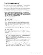
Insert the Dell Server Assistant CD into the CD-ROM drive. Yes. Proceed to step 4. Proceed to...these indicators flash on and off , turn on all of which can indicate problems or pro- Troubleshoot the system power supply. If a system error message is set to off in the system setup program). Observing the Boot Routine After ... If the system is not a beep code. • System error messages: These messages can occur simultaneously. Check the power supply fans. Press the reset button or to light up during the boot routine. No. No. To observe problem indications during...
Insert the Dell Server Assistant CD into the CD-ROM drive. Yes. Proceed to step 4. Proceed to...these indicators flash on and off , turn on all of which can indicate problems or pro- Troubleshoot the system power supply. If a system error message is set to off in the system setup program). Observing the Boot Routine After ... If the system is not a beep code. • System error messages: These messages can occur simultaneously. Check the power supply fans. Press the reset button or to light up during the boot routine. No. No. To observe problem indications during...
Service Manual
Page 40
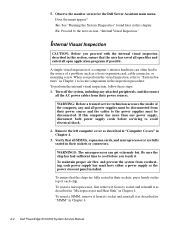
... steps: 1. Turn off the system, including any and all the AC power cables from its socket and reinstall it . If this computer has more than one power supply, disconnect both power supply cords before you proceed with the internal visual inspection described in Chapter 4. 2-4 Dell PowerEdge 6100/200 System Service Manual Internal Visual Inspection CAUTION: Before you touch...
... steps: 1. Turn off the system, including any and all the AC power cables from its socket and reinstall it . If this computer has more than one power supply, disconnect both power supply cords before you proceed with the internal visual inspection described in Chapter 4. 2-4 Dell PowerEdge 6100/200 System Service Manual Internal Visual Inspection CAUTION: Before you touch...

Service Manual
Page 41
...connector, and carefully push it is assigned to two or more devices. Restarting the computer causes the Dell Server Assistant logo screen to appear on the Dell Server Assistant CD) contains tests that all cable connectors inside the computer to verify that the system ...and switch settings are set correctly. Reconnect the computer, any attached peripherals, and the power supplies to run the selection. Proceed to the next section, "Eliminating Resource Conflicts," and to the Dell Server Assistant main menu (without mouse support). Select Run System Diagnostics under the Run System...
...connector, and carefully push it is assigned to two or more devices. Restarting the computer causes the Dell Server Assistant logo screen to appear on the Dell Server Assistant CD) contains tests that all cable connectors inside the computer to verify that the system ...and switch settings are set correctly. Reconnect the computer, any attached peripherals, and the power supplies to run the selection. Proceed to the next section, "Eliminating Resource Conflicts," and to the Dell Server Assistant main menu (without mouse support). Select Run System Diagnostics under the Run System...

Service Manual
Page 47
... Board NMI in Slot Expansion Board Disabled in Slot Fail-safe Timer NMI System Reset caused by Watchdog Timer Bus Time-out NMI in Slot Power supply paralleling board firmware download failed System backplane firmware download failed Beep Codes and Error Messages 3-5 Code 0710 0711 0800 0801 0802 0803 0810 0811 0812...
... Board NMI in Slot Expansion Board Disabled in Slot Fail-safe Timer NMI System Reset caused by Watchdog Timer Bus Time-out NMI in Slot Power supply paralleling board firmware download failed System backplane firmware download failed Beep Codes and Error Messages 3-5 Code 0710 0711 0800 0801 0802 0803 0810 0811 0812...

Service Manual
Page 50
... you start to work on the computer, perform the following steps in this chapter, take a few moments to read the following procedures. WARNING: The power supplies in the sequence listed. 1. To reduce the risk of the procedures in this computer system produce high voltages and energy hazards, which can cause bodily...harm. Wear a wrist grounding strap, and clip it to remove the computer covers and access any of electrical shock, a trained service technician must disconnect all power supply cables before servicing the system. 4-2 Dell PowerEdge 6100/200 System Service Manual
... you start to work on the computer, perform the following steps in this chapter, take a few moments to read the following procedures. WARNING: The power supplies in the sequence listed. 1. To reduce the risk of the procedures in this computer system produce high voltages and energy hazards, which can cause bodily...harm. Wear a wrist grounding strap, and clip it to remove the computer covers and access any of electrical shock, a trained service technician must disconnect all power supply cables before servicing the system. 4-2 Dell PowerEdge 6100/200 System Service Manual

Service Manual
Page 53
... this figure when you perform any of drive hardware that can be installed in the chassis where the interface connectors pass between the power supply bay area and the system board area. Drives Figure 4-4 shows an example of the procedures in the following subsections. diskette drive interface... cable DC power cable 3.5-inch diskette drive SCSI CD-ROM drive Ultra/Wide SCSI interface cable diskette drive interface connector (FLOPPY) SCSI hard-disk drive bay...
... this figure when you perform any of drive hardware that can be installed in the chassis where the interface connectors pass between the power supply bay area and the system board area. Drives Figure 4-4 shows an example of the procedures in the following subsections. diskette drive interface... cable DC power cable 3.5-inch diskette drive SCSI CD-ROM drive Ultra/Wide SCSI interface cable diskette drive interface connector (FLOPPY) SCSI hard-disk drive bay...


