Service Manual
Page 4
... 3 Beep Codes and Error Messages 3-1 POST Beep Codes 3-1 System Error Messages 3-2 Chapter 4 Removing and Replacing Parts 4-1 Recommended Tools 4-1 Precautionary Measures 4-2 Computer Covers 4-3 Front Bezel 4-4 Drives 4-5 Front-Panel Inserts 4-6 Externally Accessible Drives 4-7 Hard-Disk Drives 4-9 SCSI Backplane Board 4-11 Power Supply 4-12 Power-Supply Paralleling Board 4-13 Control Panel 4-14 Cooling Fans 4-15 System Board Components 4-16 Expansion Cards 4-17 Support Panel 4-18 Memory, Microprocessor, and Termination Module 4-19 SIMM 4-20 Microprocessor and Heat Sink...
... 3 Beep Codes and Error Messages 3-1 POST Beep Codes 3-1 System Error Messages 3-2 Chapter 4 Removing and Replacing Parts 4-1 Recommended Tools 4-1 Precautionary Measures 4-2 Computer Covers 4-3 Front Bezel 4-4 Drives 4-5 Front-Panel Inserts 4-6 Externally Accessible Drives 4-7 Hard-Disk Drives 4-9 SCSI Backplane Board 4-11 Power Supply 4-12 Power-Supply Paralleling Board 4-13 Control Panel 4-14 Cooling Fans 4-15 System Board Components 4-16 Expansion Cards 4-17 Support Panel 4-18 Memory, Microprocessor, and Termination Module 4-19 SIMM 4-20 Microprocessor and Heat Sink...
Service Manual
Page 9
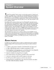
... KB of cache memory internal to each Pentium Pro microprocessor • 64 MB of DRAM main memory (standard), upgradable to 2 GB • SCSI backplane board supporting up to the EISA bus, with optional redundant power supplies, RAID capability, hot-pluggable SCSI hard-disk drives, thermal and power supply monitoring, redundant fans, and ECC memory. PowerEdge 6100 systems incorporate the high-performance PCI local bus as well as the EISA expansion bus. Contact Dell for the Dell PowerEdge 6100/200 system is 200...
... KB of cache memory internal to each Pentium Pro microprocessor • 64 MB of DRAM main memory (standard), upgradable to 2 GB • SCSI backplane board supporting up to the EISA bus, with optional redundant power supplies, RAID capability, hot-pluggable SCSI hard-disk drives, thermal and power supply monitoring, redundant fans, and ECC memory. PowerEdge 6100 systems incorporate the high-performance PCI local bus as well as the EISA expansion bus. Contact Dell for the Dell PowerEdge 6100/200 system is 200...

Service Manual
Page 10
... system features, see the "Dell PowerEdge 4100 and 6100 Systems Rack Kit Installation Guide" (P/N 40722). For information about installing the PowerEdge 6100 systems in this chapter. • BIOS in upgradable flash memory attached to the EISA bus • Integrated super I/O controller attached to the EISA bus, provides a bidirectional parallel port, two serial ports, and the diskette drive interface • Two integrated Ultra/Wide SCSI controllers • Integrated server management circuitry that the location or direction relative to...
... system features, see the "Dell PowerEdge 4100 and 6100 Systems Rack Kit Installation Guide" (P/N 40722). For information about installing the PowerEdge 6100 systems in this chapter. • BIOS in upgradable flash memory attached to the EISA bus • Integrated super I/O controller attached to the EISA bus, provides a bidirectional parallel port, two serial ports, and the diskette drive interface • Two integrated Ultra/Wide SCSI controllers • Integrated server management circuitry that the location or direction relative to...

Service Manual
Page 16
... the SCSI hard-disk drive bays. These bays can contain up to external SCSI devices. This controller also provides a SCSI interface to six 1- NOTES: The externally accessible drive bays at the front of a high-speed, high-resolution, SVGA-compatible video subsystem. Integrated Server Management The system board contains integrated server management circuitry that monitors critical system voltages and temperatures, as well as the operation of four EISA expansion-card connectors and six PCI expansion-card connectors. For 1-8 Dell PowerEdge 6100/200 System Service Manual
... the SCSI hard-disk drive bays. These bays can contain up to external SCSI devices. This controller also provides a SCSI interface to six 1- NOTES: The externally accessible drive bays at the front of a high-speed, high-resolution, SVGA-compatible video subsystem. Integrated Server Management The system board contains integrated server management circuitry that monitors critical system voltages and temperatures, as well as the operation of four EISA expansion-card connectors and six PCI expansion-card connectors. For 1-8 Dell PowerEdge 6100/200 System Service Manual
Service Manual
Page 18
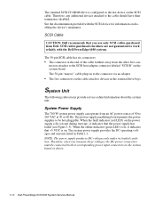
... LED) is lit, it indicates that +5 VDC is lit (except during start-up), it indicates that you measure these voltages, the DC power connectors must be hot-pluggable. See the documentation provided with the Dell PowerEdge 6100 systems. The 50-pin SCSI cable has six connectors: • The connector at 50 or 60 Hz. SCSI Cable CAUTION: Dell recommends that the power supply has failed (see Figure 1-5). Therefore, when you use...
... LED) is lit, it indicates that +5 VDC is lit (except during start-up), it indicates that you measure these voltages, the DC power connectors must be hot-pluggable. See the documentation provided with the Dell PowerEdge 6100 systems. The 50-pin SCSI cable has six connectors: • The connector at 50 or 60 Hz. SCSI Cable CAUTION: Dell recommends that the power supply has failed (see Figure 1-5). Therefore, when you use...

Service Manual
Page 24
...; HD LED 2 • J2A3 • C5B1 1-16 Dell PowerEdge 6100/200 System Service Manual power connector (PS3) mouse connector (MOUSE) power connector (PS1 or PS2) power connector (PS1 or PS2) diskette drive interface connector (FLOPPY) control panel connector (FRONT PANEL) keyboard connector (KEYBD) serial port 1 connector (SERIAL1) serial port 2 connector (SERIAL2) video connector (MONITOR) parallel port connector (PARALLEL) jumpers and switches real-time clock memory module connector (MEMORY MODULE) front of system board secondary microprocessor module connector (PROCESSOR MODULE...
...; HD LED 2 • J2A3 • C5B1 1-16 Dell PowerEdge 6100/200 System Service Manual power connector (PS3) mouse connector (MOUSE) power connector (PS1 or PS2) power connector (PS1 or PS2) diskette drive interface connector (FLOPPY) control panel connector (FRONT PANEL) keyboard connector (KEYBD) serial port 1 connector (SERIAL1) serial port 2 connector (SERIAL2) video connector (MONITOR) parallel port connector (PARALLEL) jumpers and switches real-time clock memory module connector (MEMORY MODULE) front of system board secondary microprocessor module connector (PROCESSOR MODULE...

Service Manual
Page 26
...Disables BIOS update of flash memory. Settings in CMOS and the RTC are reset to factory defaults during reset. Disables 2.88-MB size detection. Enables forced 2.88-MB diskette drive size detection. 1-18 Dell PowerEdge 6100/200 System Service Manual CLEAR PASSWORD Clears all passwords. (default) Retains all passwords. Enables recovery mode for BIOS flash memory (the BIOS WRITE jumper must also be in CMOS and the RTC are retained during reset. BIOS RECOVERY BOOT BLOCK PROTECT (default) Normal BIOS boot operation. System-Board Jumper and Switch Descriptions Jumper/Switch...
...Disables BIOS update of flash memory. Settings in CMOS and the RTC are reset to factory defaults during reset. Disables 2.88-MB size detection. Enables forced 2.88-MB diskette drive size detection. 1-18 Dell PowerEdge 6100/200 System Service Manual CLEAR PASSWORD Clears all passwords. (default) Retains all passwords. Enables recovery mode for BIOS flash memory (the BIOS WRITE jumper must also be in CMOS and the RTC are retained during reset. BIOS RECOVERY BOOT BLOCK PROTECT (default) Normal BIOS boot operation. System-Board Jumper and Switch Descriptions Jumper/Switch...

Service Manual
Page 35
Cirrus CL-GD5424 device; Table 1-7. VGA connector Video memory 1 MB (not upgradeable) Key Combinations Technical Specifications (continued) Video Video type embedded ISA;
Cirrus CL-GD5424 device; Table 1-7. VGA connector Video memory 1 MB (not upgradeable) Key Combinations Technical Specifications (continued) Video Video type embedded ISA;

Service Manual
Page 38
... monitor. Inspect all power cables are firmly attached to the interface connector on the back of the computer. Inspect the keyboard to ensure that secure these steps: 1. Yes. Proceed to the next section, "Observing the Boot Routine." 2-2 Dell PowerEdge 6100/200 System Service Manual For a serial mouse, the mouse interface cable must be attached to replace the keyboard. 8. Proceed to the appropriate procedure in Chapter 4, "Removing...
... monitor. Inspect all power cables are firmly attached to the interface connector on the back of the computer. Inspect the keyboard to ensure that secure these steps: 1. Yes. Proceed to the next section, "Observing the Boot Routine." 2-2 Dell PowerEdge 6100/200 System Service Manual For a serial mouse, the mouse interface cable must be attached to replace the keyboard. 8. Proceed to the appropriate procedure in Chapter 4, "Removing...
Service Manual
Page 39
... problems. NOTE: Most of the steps in response to data being transferred to or from the drives. If a system error message is displayed, see Table 3-1. No. Do these indicators flash on the upper-right corner of beeps that the system power supply is not a beep code. • System error messages: These messages can occur simultaneously. vide status information. Press the reset button or to step 4. Yes. Troubleshoot the system power supply...
... problems. NOTE: Most of the steps in response to data being transferred to or from the drives. If a system error message is displayed, see Table 3-1. No. Do these indicators flash on the upper-right corner of beeps that the system power supply is not a beep code. • System error messages: These messages can occur simultaneously. vide status information. Press the reset button or to step 4. Yes. Troubleshoot the system power supply...
Service Manual
Page 40
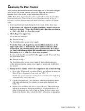
... a problem, such as described in "Computer Covers" in Chapter 4. 2-4 Dell PowerEdge 6100/200 System Service Manual To reseat a microprocessor, first remove it from overheating, each chip. No. Verify that the user has saved all open application programs if possible. Observe the monitor screen for the Dell Server Assistant main menu. See "Running the System Diagnostics" found later in this computer has more than one power supply, disconnect both power supply...
... a problem, such as described in "Computer Covers" in Chapter 4. 2-4 Dell PowerEdge 6100/200 System Service Manual To reseat a microprocessor, first remove it from overheating, each chip. No. Verify that the user has saved all open application programs if possible. Observe the monitor screen for the Dell Server Assistant main menu. See "Running the System Diagnostics" found later in this computer has more than one power supply, disconnect both power supply...

Service Manual
Page 41
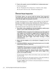
... computer cover. 7. Does the problem appear to be rebooted to reseat an expansion card, remove the card as necessary. Because a device may require dedicated memory spaces, interrupt levels, or DMA channels, all of which must be resolved? Resource conflicts can result in this chapter. For information about these jumpers and switches, see "System Board Jumpers and Switches" and "Microprocessor Module Jumpers" in troubleshooting all jumper and switch settings are necessary. No. A message...
... computer cover. 7. Does the problem appear to be rebooted to reseat an expansion card, remove the card as necessary. Because a device may require dedicated memory spaces, interrupt levels, or DMA channels, all of which must be resolved? Resource conflicts can result in this chapter. For information about these jumpers and switches, see "System Board Jumpers and Switches" and "Microprocessor Module Jumpers" in troubleshooting all jumper and switch settings are necessary. No. A message...
Service Manual
Page 42
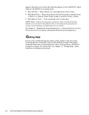
... Installation and Troubleshooting Guide. 2-6 Dell PowerEdge 6100/200 System Service Manual For instructions, see Chapter 11, "Getting Help," in the system diagnostics reveals the source of the problem or leads to isolate a failure • Run Specific Tests - appears, allowing you to choose the following options or exit to MS-DOS, which returns to be inserted in the Installation and Troubleshooting Guide for a thorough check of the problem, call Dell for technical assistance. Runs...
... Installation and Troubleshooting Guide. 2-6 Dell PowerEdge 6100/200 System Service Manual For instructions, see Chapter 11, "Getting Help," in the system diagnostics reveals the source of the problem or leads to isolate a failure • Run Specific Tests - appears, allowing you to choose the following options or exit to MS-DOS, which returns to be inserted in the Installation and Troubleshooting Guide for a thorough check of the problem, call Dell for technical assistance. Runs...
Service Manual
Page 43
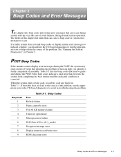
... operation. The tables in this chapter list faults that can occur during system start-up or, in the case of beeps that identifies the problem or that can cause a beep code or system error message to assist in the CD-based diagnostics to occur. Table 3-1 lists the beep codes that may emit a series of some failures, during the POST. If a faulty system does not emit beep codes or display...
... operation. The tables in this chapter list faults that can occur during system start-up or, in the case of beeps that identifies the problem or that can cause a beep code or system error message to assist in the CD-based diagnostics to occur. Table 3-1 lists the beep codes that may emit a series of some failures, during the POST. If a faulty system does not emit beep codes or display...
Service Manual
Page 44
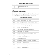
... be rebooted until an appropriate hardware change has been made. These messages can appear on the monitor screen. Some of EISA ROM Failed 3-2 Dell PowerEdge 6100/200 System Service Manual Please Unlock It 0070 CMOS Time & Date Not Set 0080 Option ROM has bad checksum 0083 Shadow of PCI ROM Failed 0084 Shadow of these error messages indicate fatal errors. Code 0002 Table 3-2. System Messages Message Primary Boot Device Not Found 0010 Cache Memory Failure, Do Not Enable Cache...
... be rebooted until an appropriate hardware change has been made. These messages can appear on the monitor screen. Some of EISA ROM Failed 3-2 Dell PowerEdge 6100/200 System Service Manual Please Unlock It 0070 CMOS Time & Date Not Set 0080 Option ROM has bad checksum 0083 Shadow of PCI ROM Failed 0084 Shadow of these error messages indicate fatal errors. Code 0002 Table 3-2. System Messages Message Primary Boot Device Not Found 0010 Cache Memory Failure, Do Not Enable Cache...

Service Manual
Page 73
... danger of a burn, be hot. tem configuration utility. Cut the cable tie that are located near the microprocessors. Discard the RTC chip according to the system board. Removing and Replacing Parts 4-25 Remove the support panel and the primary microprocessor module. 5. You will be careful when removing or installing system board components that secures the chip to the manufacturer's instructions. NOTE: The cable tie binding the chip to...
... danger of a burn, be hot. tem configuration utility. Cut the cable tie that are located near the microprocessors. Discard the RTC chip according to the system board. Removing and Replacing Parts 4-25 Remove the support panel and the primary microprocessor module. 5. You will be careful when removing or installing system board components that secures the chip to the manufacturer's instructions. NOTE: The cable tie binding the chip to...

Service Manual
Page 83
... Peripheral Configuration Configuration Mode Standard IDE Interface Floppy Interface Serial Port 1 Address Serial Port 2 Address Parallel Port Address Parallel Port Mode Parallel Port ECP-DMA Serial Port 1 IRQ Serial Port 2 IRQ Parallel Port IRQ Onboard SCSI-A ROM Scan Onboard SCSI-B ROM Scan Console Redirection Auto Disabled Enabled COM1, 3F8h COM2, 2F8h LPT1, 378h ISA Compatible Disabled IRQ4 IRQ3 IRQ7 F1 ESC Enter F5 F6 F10 Help Back Select Previous Item Next Item Select Menu Setup Defaults Previous Value Save & Exit Enable Enable Disable Figure A-4. Peripheral Configuration...
... Peripheral Configuration Configuration Mode Standard IDE Interface Floppy Interface Serial Port 1 Address Serial Port 2 Address Parallel Port Address Parallel Port Mode Parallel Port ECP-DMA Serial Port 1 IRQ Serial Port 2 IRQ Parallel Port IRQ Onboard SCSI-A ROM Scan Onboard SCSI-B ROM Scan Console Redirection Auto Disabled Enabled COM1, 3F8h COM2, 2F8h LPT1, 378h ISA Compatible Disabled IRQ4 IRQ3 IRQ7 F1 ESC Enter F5 F6 F10 Help Back Select Previous Item Next Item Select Menu Setup Defaults Previous Value Save & Exit Enable Enable Disable Figure A-4. Peripheral Configuration...

Service Manual
Page 86
...'s hardware revision level. Dell setting is 1.4, the correct value for the Dell PowerEdge 6100 system. A-10 Dell PowerEdge 6100/200 System Service Manual PIC Interrupt Routing Connects the interrupt mapping to the microprocessor's local APIC through the I /O APIC. GAT Mode Options are reset, change this value from the microprocessor bus. Advanced Chipset Configuration Submenu Categories (continued) Category Function MPS Version Specifies MultiProcessor Specification (MPS) number used by operating system. Second I/O APIC Enables or disables (default...
...'s hardware revision level. Dell setting is 1.4, the correct value for the Dell PowerEdge 6100 system. A-10 Dell PowerEdge 6100/200 System Service Manual PIC Interrupt Routing Connects the interrupt mapping to the microprocessor's local APIC through the I /O APIC. GAT Mode Options are reset, change this value from the microprocessor bus. Advanced Chipset Configuration Submenu Categories (continued) Category Function MPS Version Specifies MultiProcessor Specification (MPS) number used by operating system. Second I/O APIC Enables or disables (default...

Service Manual
Page 88
... (PCI Clocks) Ensures that a PCI card accesses the PCI bus within specified number of PCI clocks. Boot With PnP OS Determines how the non-boot devices are initialized. Security Menu A-12 Dell PowerEdge 6100/200 System Service Manual Set to None (default), BIOS initializes all non-boot devices. Windows 95 is not an option on this system. Set to Other, operating system initializes all non-boot devices. Table A-7. Security Menu Security Options User Password Is Administrative Password Is Set User Password Set Administrative Password Unattended Start Security Hot Key...
... (PCI Clocks) Ensures that a PCI card accesses the PCI bus within specified number of PCI clocks. Boot With PnP OS Determines how the non-boot devices are initialized. Security Menu A-12 Dell PowerEdge 6100/200 System Service Manual Set to None (default), BIOS initializes all non-boot devices. Windows 95 is not an option on this system. Set to Other, operating system initializes all non-boot devices. Table A-7. Security Menu Security Options User Password Is Administrative Password Is Set User Password Set Administrative Password Unattended Start Security Hot Key...
Service Manual
Page 96
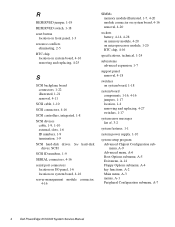
... board, 4-16 removal, 4-20 sockets battery, 4-14, 4-28 on memory module, 4-20 on microprocessor module, 1-20 RTC chip, 4-16 specifications, technical, 1-24 subsystems advanced expansion, 1-7 support panel removal, 4-18 switches on system board, 4-16 removing and replacing, 4-25 S SCSI backplane board connectors, 1-22 illustrated, 1-21 removal, 4-11 SCSI cable, 1-10 SCSI connectors, 4-16 SCSI controllers, integrated, 1-8 SCSI devices cable, 1-9, 1-10 external, slots, 1-6 ID numbers, 1-9 termination, 1-9 SCSI hard-disk drives. R RESERVED jumper, 1-19 RESERVED switch, 1-18 reset button location...
... board, 4-16 removal, 4-20 sockets battery, 4-14, 4-28 on memory module, 4-20 on microprocessor module, 1-20 RTC chip, 4-16 specifications, technical, 1-24 subsystems advanced expansion, 1-7 support panel removal, 4-18 switches on system board, 4-16 removing and replacing, 4-25 S SCSI backplane board connectors, 1-22 illustrated, 1-21 removal, 4-11 SCSI cable, 1-10 SCSI connectors, 4-16 SCSI controllers, integrated, 1-8 SCSI devices cable, 1-9, 1-10 external, slots, 1-6 ID numbers, 1-9 termination, 1-9 SCSI hard-disk drives. R RESERVED jumper, 1-19 RESERVED switch, 1-18 reset button location...


