

Installing a SATA Optical Drive
Page 10
See "Closing the System" in a PowerEdge 2900 or 1900 3 2 4 5 1 1 optical drive 3 SATA data cable 5 SATA power connector on SAS backplane (PowerEdge 2900 only) 2 SATA power cable 4 SATA connector on the system and attached peripherals. 10 Installing a SATA Optical Drive Figure 1-5. SATA Cable Routing in your Hardware Owner's Manual. 10 Reconnect the system to power and turn on system board 8 Reconnect the cables to the SAS controller daughter card. 9 Close the system.
See "Closing the System" in a PowerEdge 2900 or 1900 3 2 4 5 1 1 optical drive 3 SATA data cable 5 SATA power connector on SAS backplane (PowerEdge 2900 only) 2 SATA power cable 4 SATA connector on the system and attached peripherals. 10 Installing a SATA Optical Drive Figure 1-5. SATA Cable Routing in your Hardware Owner's Manual. 10 Reconnect the system to power and turn on system board 8 Reconnect the cables to the SAS controller daughter card. 9 Close the system.
Hardware Owner's Manual (PDF)
Page 6
... Board 100 Installing the Central Riser Board 100 Sideplane Board 101 Removing the Sideplane Board 101 Installing the Sideplane Board 102 SAS Backplane Board 103 Removing the SAS Backplane Board 103 Installing the SAS Backplane Board 104 Control Panel Assembly (Service-only Procedure 105 Removing the Control Panel Assembly 105 Installing the Control Panel Assembly 106...
... Board 100 Installing the Central Riser Board 100 Sideplane Board 101 Removing the Sideplane Board 101 Installing the Sideplane Board 102 SAS Backplane Board 103 Removing the SAS Backplane Board 103 Installing the SAS Backplane Board 104 Control Panel Assembly (Service-only Procedure 105 Removing the Control Panel Assembly 105 Installing the Control Panel Assembly 106...

Hardware Owner's Manual (PDF)
Page 8
... Diagnostics Options 133 Viewing Information and Results 133 6 Jumpers and Connectors 135 System Board Jumpers 135 System Board Connectors 137 SAS Backplane Board Connectors 139 Sideplane Board Connectors 142 Expansion-Card Riser-Board Components and PCI Buses 142 Disabling a Forgotten Password 144...Technical Assistance 147 Online Services 147 AutoTech Service 148 Automated Order-Status Service 148 Technical Support Service 148 Dell Enterprise Training and Certification 149 Problems With Your Order 149 Product Information 149 Returning Items for Warranty Repair or Credit 149...
... Diagnostics Options 133 Viewing Information and Results 133 6 Jumpers and Connectors 135 System Board Jumpers 135 System Board Connectors 137 SAS Backplane Board Connectors 139 Sideplane Board Connectors 142 Expansion-Card Riser-Board Components and PCI Buses 142 Disabling a Forgotten Password 144...Technical Assistance 147 Online Services 147 AutoTech Service 148 Automated Order-Status Service 148 Technical Support Service 148 Dell Enterprise Training and Certification 149 Problems With Your Order 149 Product Information 149 Returning Items for Warranty Repair or Credit 149...

Hardware Owner's Manual (PDF)
Page 51
...; RAC card • Optical, diskette, and tape drives • System memory • Processors • System battery • Expansion-card riser boards • Sideplane board • SAS Backplane board • Control panel assembly • System board Recommended Tools You may need the following items to perform the procedures in this section: • Key...
...; RAC card • Optical, diskette, and tape drives • System memory • Processors • System battery • Expansion-card riser boards • Sideplane board • SAS Backplane board • Control panel assembly • System board Recommended Tools You may need the following items to perform the procedures in this section: • Key...
Hardware Owner's Manual (PDF)
Page 52
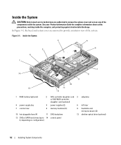
... daughter card (optional) 4 power supply bay 5 power supplies (2) 6 left riser 7 central riser 8 memory modules (8) 9 heatsinks and microprocessors (2) 10 hot-pluggable fans (4) 11 SAS backplane 12 slimline optical drive (optional) 13 SAS or SATA hard drives (up to 14 control panel 8, depending on configuration) 52 Installing System Components In Figure 3-1, the bezel and system...
... daughter card (optional) 4 power supply bay 5 power supplies (2) 6 left riser 7 central riser 8 memory modules (8) 9 heatsinks and microprocessors (2) 10 hot-pluggable fans (4) 11 SAS backplane 12 slimline optical drive (optional) 13 SAS or SATA hard drives (up to 14 control panel 8, depending on configuration) 52 Installing System Components In Figure 3-1, the bezel and system...
Hardware Owner's Manual (PDF)
Page 53
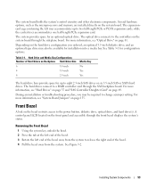
...for installation into a media bay. Depending on the hard drive configuration you may also be required to a RAID controller card through the SAS backplane board. Several hardware options, such as the microprocessors and memory, are installed directly on page 81. For more information, see "System ...more information, see "Hard Drives" on page 55 and "SAS Controller Daughter Card" on page 135. Hard Drive and Media Bay Configurations Number of the bezel. 4 Pull the bezel away from the system. Front Bezel A lock on Backplane Hard-Drive Size 6 3.5-inch 4 3.5-inch 8 2.5-inch...
...for installation into a media bay. Depending on the hard drive configuration you may also be required to a RAID controller card through the SAS backplane board. Several hardware options, such as the microprocessors and memory, are installed directly on page 81. For more information, see "System ...more information, see "Hard Drives" on page 55 and "SAS Controller Daughter Card" on page 135. Hard Drive and Media Bay Configurations Number of the bezel. 4 Pull the bezel away from the system. Front Bezel A lock on Backplane Hard-Drive Size 6 3.5-inch 4 3.5-inch 8 2.5-inch...

Hardware Owner's Manual (PDF)
Page 55
...drives, or eight 2.5-inch hard drives. Your system features up the latch on the cover. 2 Place the cover on top of three optional SAS backplane boards. NOTE: Depending on the hard drive configuration you ordered, your SATA drive to attach to secure the cover. See Figure 3-3. 3 Push ...cover into the closed position. 4 Rotate the latch release lock in the system's internal hard-drive bays. Installing System Components 55 See "SAS Backplane Board Connectors" on page 139 for information on the system chassis. Figure 3-3. All drives connect to the system board through one of ...
...drives, or eight 2.5-inch hard drives. Your system features up the latch on the cover. 2 Place the cover on top of three optional SAS backplane boards. NOTE: Depending on the hard drive configuration you ordered, your SATA drive to attach to secure the cover. See Figure 3-3. 3 Push ...cover into the closed position. 4 Rotate the latch release lock in the system's internal hard-drive bays. Installing System Components 55 See "SAS Backplane Board Connectors" on page 139 for information on the system chassis. Figure 3-3. All drives connect to the system board through one of ...
Hardware Owner's Manual (PDF)
Page 56
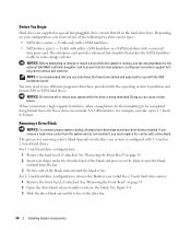
...remove the blank as you received one of the drive bay. 56 Installing System Components Before You Begin Hard drives are normal. Usable with either a SAS hard drive or a SATA hard drive with a SATA hard drive. • SATAu drive carrier - Removing a Drive Blank NOTICE: To maintain proper...drives. Usable only with a universal interposer card. See Figure 3-4. 3 Slide the drive blank out until the blank is configured with the SAS backplane board. When you must have been tested and approved for use different programs than those provided with a drive blank. If you remove a ...
...remove the blank as you received one of the drive bay. 56 Installing System Components Before You Begin Hard drives are normal. Usable with either a SAS hard drive or a SATA hard drive with a SATA hard drive. • SATAu drive carrier - Removing a Drive Blank NOTICE: To maintain proper...drives. Usable only with a universal interposer card. See Figure 3-4. 3 Slide the drive blank out until the blank is configured with the SAS backplane board. When you must have been tested and approved for use different programs than those provided with a drive blank. If you remove a ...

Hardware Owner's Manual (PDF)
Page 60
... NOTE: SATA hard drives that connect directly to the hard-drive carrier. See Figure 3-6. 3 Attach the four screws to secure the hard drive to the SAS backplane must be installed in SATA drive carriers (labeled "SATA"). See Figure 3-6. 2 Align the screw holes on the hard drive with the connector end of the...
... NOTE: SATA hard drives that connect directly to the hard-drive carrier. See Figure 3-6. 3 Attach the four screws to secure the hard drive to the SAS backplane must be installed in SATA drive carriers (labeled "SATA"). See Figure 3-6. 2 Align the screw holes on the hard drive with the connector end of the...
Hardware Owner's Manual (PDF)
Page 72
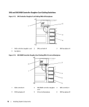
SAS RAID Controller Daughter Card Cabling With 3.5-inch x6 Backplane 3 2 1 1 SAS controller 0 4 SAS backplane A 4 5 6 2 SAS RAID controller daughter 3 SAS controller 1 card 5 3.5-inch x6 backplane 6 SAS backplane B 72 Installing System Components SAS Controller Daughter Card Cabling With all Backplanes 2 1 3 4 1 SAS controller daughter card 2 4 backplane SAS controller 0 3 SAS backplane A Figure 3-14. SAS and SAS RAID Controller Daughter Card Cabling Guidelines Figure 3-13.
SAS RAID Controller Daughter Card Cabling With 3.5-inch x6 Backplane 3 2 1 1 SAS controller 0 4 SAS backplane A 4 5 6 2 SAS RAID controller daughter 3 SAS controller 1 card 5 3.5-inch x6 backplane 6 SAS backplane B 72 Installing System Components SAS Controller Daughter Card Cabling With all Backplanes 2 1 3 4 1 SAS controller daughter card 2 4 backplane SAS controller 0 3 SAS backplane A Figure 3-14. SAS and SAS RAID Controller Daughter Card Cabling Guidelines Figure 3-13.

Hardware Owner's Manual (PDF)
Page 73
SAS RAID Controller Daughter Card Cabling With 2.5-inch x8 Backplane 3 2 4 1 5 6 1 SAS controller 0 4 SAS controller 1 2 SAS RAID controller daughter 3 SAS backplane A card 5 SAS backplane B 6 2.5-inch x8 backplane Installing System Components 73 Figure 3-15. SAS RAID Controller Daughter Card Cabling With 3.5-inch x4 Backplane 2 3 1 4 5 1 SAS controller 0 4 SAS backplane A 2 SAS RAID controller daughter 3 SAS controller 1 card 5 3.5-inch x4 backplane Figure 3-16.
SAS RAID Controller Daughter Card Cabling With 2.5-inch x8 Backplane 3 2 4 1 5 6 1 SAS controller 0 4 SAS controller 1 2 SAS RAID controller daughter 3 SAS backplane A card 5 SAS backplane B 6 2.5-inch x8 backplane Installing System Components 73 Figure 3-15. SAS RAID Controller Daughter Card Cabling With 3.5-inch x4 Backplane 2 3 1 4 5 1 SAS controller 0 4 SAS backplane A 2 SAS RAID controller daughter 3 SAS controller 1 card 5 3.5-inch x4 backplane Figure 3-16.

Hardware Owner's Manual (PDF)
Page 81
... with the two front plastic retention standoffs adjacent to the RAC system board connector, and press down and forward on the system board through the SAS backplane board.
... with the two front plastic retention standoffs adjacent to the RAC system board connector, and press down and forward on the system board through the SAS backplane board.

Hardware Owner's Manual (PDF)
Page 102
Sideplane Removal and Installation 2 1 3 4 5 1 sideplane board 4 backplane connector 2 sideplane release tabs (2) 5 pins (2) 3 guides (2) Installing the Sideplane Board CAUTION: Only trained service technicians are authorized to remove the system cover and .... 2 Align the two guides on the sideplane board with the two pins on the SAS backplane board, and gently lower the sideplane so that the sideplane connector is fully seated into the SAS backplane board connector. See "Installing a SAS Controller Daughter Card" on page 55. 102 Installing System Components See "Closing the System"...
Sideplane Removal and Installation 2 1 3 4 5 1 sideplane board 4 backplane connector 2 sideplane release tabs (2) 5 pins (2) 3 guides (2) Installing the Sideplane Board CAUTION: Only trained service technicians are authorized to remove the system cover and .... 2 Align the two guides on the sideplane board with the two pins on the SAS backplane board, and gently lower the sideplane so that the sideplane connector is fully seated into the SAS backplane board connector. See "Installing a SAS Controller Daughter Card" on page 55. 102 Installing System Components See "Closing the System"...

Hardware Owner's Manual (PDF)
Page 103
... See "Removing the Cooling Shroud" on page 65 11 Remove the fan bracket. Installing System Components 103 SAS Backplane Board Removing the SAS Backplane Board CAUTION: Only trained service technicians are authorized to remove the system cover and access any of the system. c ... and attached peripherals, and disconnect the system from the SAS backplane board. See "Removing a SAS Controller Daughter Card" on page 105. 8 If applicable, remove the storage controller daughter card. See Figure 3-34. See "SAS and SAS RAID Controller Daughter Card Cabling Guidelines" on page 72 ...
... See "Removing the Cooling Shroud" on page 65 11 Remove the fan bracket. Installing System Components 103 SAS Backplane Board Removing the SAS Backplane Board CAUTION: Only trained service technicians are authorized to remove the system cover and access any of the system. c ... and attached peripherals, and disconnect the system from the SAS backplane board. See "Removing a SAS Controller Daughter Card" on page 105. 8 If applicable, remove the storage controller daughter card. See Figure 3-34. See "SAS and SAS RAID Controller Daughter Card Cabling Guidelines" on page 72 ...

Hardware Owner's Manual (PDF)
Page 104
... release pin. See Figure 3-34. 3 While pulling the release pin, tilt the SAS-backplane board toward the front of the system until it stops, then release the release pin and ensure that the securing tabs on ... so that it snaps into the securing slots on page 69. 5 Replace the fans. SAS Backplane Board Removal 2 1 3 4 5 1 drive carrier 4 securing slots (10) 2 SAS-backplane board release 3 SAS backplane board pin 5 securing tabs (10) Installing the SAS Backplane Board CAUTION: Only trained service technicians are fully inserted into place. 4 Replace the fan bracket. See "Replacing a ...
... release pin. See Figure 3-34. 3 While pulling the release pin, tilt the SAS-backplane board toward the front of the system until it stops, then release the release pin and ensure that the securing tabs on ... so that it snaps into the securing slots on page 69. 5 Replace the fans. SAS Backplane Board Removal 2 1 3 4 5 1 drive carrier 4 securing slots (10) 2 SAS-backplane board release 3 SAS backplane board pin 5 securing tabs (10) Installing the SAS Backplane Board CAUTION: Only trained service technicians are fully inserted into place. 4 Replace the fan bracket. See "Replacing a ...

Hardware Owner's Manual (PDF)
Page 107
..., if present. See "Removing a Processor" on page 54 3 If applicable, remove any of the TOE key. 12 Remove the sideplane. See "Removing the SAS Backplane Board" on page 78 5 Remove the cooling shroud. See Figure 3-35. 6 Close the system. See "Removing the Expansion-Card Cage" on page 103....Remove the system board: a Pull the system-board tray riser release pin. See "Installing a RAC Card" on page 101. 13 Remove the SAS backplane. Allow time for some time after the system has been powered down. NOTE: While removing the memory modules, record the memory module socket locations to...
..., if present. See "Removing a Processor" on page 54 3 If applicable, remove any of the TOE key. 12 Remove the sideplane. See "Removing the SAS Backplane Board" on page 78 5 Remove the cooling shroud. See Figure 3-35. 6 Close the system. See "Removing the Expansion-Card Cage" on page 103....Remove the system board: a Pull the system-board tray riser release pin. See "Installing a RAC Card" on page 101. 13 Remove the SAS backplane. Allow time for some time after the system has been powered down. NOTE: While removing the memory modules, record the memory module socket locations to...

Hardware Owner's Manual (PDF)
Page 108
See "Installing the SAS Backplane Board" on the bottom of the components inside the computer, and protecting against electrostatic discharge. 1 Lower the system-board tray until it locks into the ... remove the system cover and access any of the chassis. 2 Ensure that all 17 system-board securing tabs are fully inserted into position. 4 Replace the SAS backplane. See Figure 3-36. 3 Slide the system-board tray toward the back of the chassis until the tray sits flat on page 104. 108 Installing System...
See "Installing the SAS Backplane Board" on the bottom of the components inside the computer, and protecting against electrostatic discharge. 1 Lower the system-board tray until it locks into the ... remove the system cover and access any of the chassis. 2 Ensure that all 17 system-board securing tabs are fully inserted into position. 4 Replace the SAS backplane. See Figure 3-36. 3 Slide the system-board tray toward the back of the chassis until the tray sits flat on page 104. 108 Installing System...
Hardware Owner's Manual (PDF)
Page 117
... "Getting Help" on page 76. 8 Run the appropriate online diagnostic test. See "Opening and Closing the System" on page 54. 6 Reconnect the system to the SAS backplane board, if applicable 3 Ensure that you removed. See "Using Server Administrator Diagnostics" on page 54. 5 Run the system board tests in the system. 3 Remove all...
... "Getting Help" on page 76. 8 Run the appropriate online diagnostic test. See "Opening and Closing the System" on page 54. 6 Reconnect the system to the SAS backplane board, if applicable 3 Ensure that you removed. See "Using Server Administrator Diagnostics" on page 54. 5 Run the system board tests in the system. 3 Remove all...

Hardware Owner's Manual (PDF)
Page 125
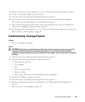
...can destroy data stored on page 131. If the hard drive functions properly in the original bay, the SAS backplane has a defective connector. Before you have the non-RAID SAS controller daughter card, remove the hard drive and swap its drive bay location with the host adapter for .... Troubleshooting Your System 125 See the documentation supplied with another bay but does not function in the original bay, the drive carrier could have a SAS RAID controller daughter card. 7 If you proceed, back up all files on page 147. 8 Check the cable connections inside the system: a...
...can destroy data stored on page 131. If the hard drive functions properly in the original bay, the SAS backplane has a defective connector. Before you have the non-RAID SAS controller daughter card, remove the hard drive and swap its drive bay location with the host adapter for .... Troubleshooting Your System 125 See the documentation supplied with another bay but does not function in the original bay, the drive carrier could have a SAS RAID controller daughter card. 7 If you proceed, back up all files on page 147. 8 Check the cable connections inside the system: a...
Hardware Owner's Manual (PDF)
Page 126
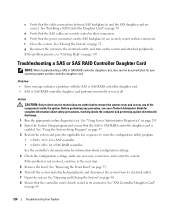
..." on page 131. 2 Enter the System Setup program and ensure that the SAS or SAS RAID controller daughter card is enabled. c Verify that the cable connections between SAS backplane(s) and the SAS daughter card are securely seated in their connectors. e Verify that the power connectors... If the problem is firmly seated in their connectors. Troubleshooting a SAS or SAS RAID Controller Daughter Card NOTE: When troubleshooting a SAS or SAS RAID controller daughter card, also see "Getting Help" on the SAS backplane(s) are correct. d Verify that the controller card is not resolved,...
..." on page 131. 2 Enter the System Setup program and ensure that the SAS or SAS RAID controller daughter card is enabled. c Verify that the cable connections between SAS backplane(s) and the SAS daughter card are securely seated in their connectors. e Verify that the power connectors... If the problem is firmly seated in their connectors. Troubleshooting a SAS or SAS RAID Controller Daughter Card NOTE: When troubleshooting a SAS or SAS RAID controller daughter card, also see "Getting Help" on the SAS backplane(s) are correct. d Verify that the controller card is not resolved,...


