
Getting Started Guide
Page 7
.... This document may not be found on the CDs that came with your system, or on support.dell.com. • CDs included with your rack solution describes how to troubleshoot the system and install or replace system components. This service may be offered... in your system into a rack. • The Hardware Owner's Manual provides information about system features and describes how to install your Product Information Guide. Dell™ Enterprise Training and Certification is available; Supported Operating Systems •...
.... This document may not be found on the CDs that came with your system, or on support.dell.com. • CDs included with your rack solution describes how to troubleshoot the system and install or replace system components. This service may be offered... in your system into a rack. • The Hardware Owner's Manual provides information about system features and describes how to install your Product Information Guide. Dell™ Enterprise Training and Certification is available; Supported Operating Systems •...

Getting Started Guide
Page 8
Installing the Rails and System in a Rack Once you need them later. See your rack installation documentation for your system and identify each item. Keep all shipping materials in case you have read the "Safety Instructions" located in the rack installation documentation for instructions on installing your system in the rack. Unpacking the System Unpack your system, install the rails and the system in a rack. 6 Getting Started With Your System
Installing the Rails and System in a Rack Once you need them later. See your rack installation documentation for your system and identify each item. Keep all shipping materials in case you have read the "Safety Instructions" located in the rack installation documentation for instructions on installing your system in the rack. Unpacking the System Unpack your system, install the rails and the system in a rack. 6 Getting Started With Your System

Getting Started Guide
Page 14
Physical Rack Height Width Depth Weight (maximum configuration) 8.656 cm (3.40 in) 44.7 cm (17.6 in) 75.68 cm (29.79 in the positive and negative x, y, and z axes (one pulse on each side of the system) of 71 G for specific system configurations, see www.dell.com/environmental_datasheets. Temperature Operating 10° to 35...
Physical Rack Height Width Depth Weight (maximum configuration) 8.656 cm (3.40 in) 44.7 cm (17.6 in) 75.68 cm (29.79 in the positive and negative x, y, and z axes (one pulse on each side of the system) of 71 G for specific system configurations, see www.dell.com/environmental_datasheets. Temperature Operating 10° to 35...
Hardware Owner's Manual (PDF)
Page 11
... options. The system indicators and features are illustrated in this document or as a separate document. • The Rack Installation Guide or Rack Installation Instructions included with your rack solution describes how to install your system into a rack. • The Getting Started Guide provides an overview of system features, setting up your system, and technical...
... options. The system indicators and features are illustrated in this document or as a separate document. • The Rack Installation Guide or Rack Installation Instructions included with your rack solution describes how to install your system into a rack. • The Getting Started Guide provides an overview of system features, setting up your system, and technical...

Hardware Owner's Manual (PDF)
Page 13
...power-on indicator lights when the system power is on the front and back panels can be used to locate a particular system within a rack. The power button controls the DC power supply output to do so by qualified support personnel or by the operating system's documentation. NOTE:... identification buttons on . About Your System 13 Front-Panel Features and Indicators Figure 1-1 shows the controls, indicators, and connectors located behind the optional rack bezel on the back blink until one of a paper clip. Use this button only if directed to the system. If the system is not...
...power-on indicator lights when the system power is on the front and back panels can be used to locate a particular system within a rack. The power button controls the DC power supply output to do so by qualified support personnel or by the operating system's documentation. NOTE:... identification buttons on . About Your System 13 Front-Panel Features and Indicators Figure 1-1 shows the controls, indicators, and connectors located behind the optional rack bezel on the back blink until one of a paper clip. Use this button only if directed to the system. If the system is not...
Hardware Owner's Manual (PDF)
Page 63
... system has a single power supply, turn off the system and all attached peripherals. For information about the cable management arm, see the system's Rack Installation Guide. 1 If your rack system, you connect the system to unlatch and lift the cable management arm if it must be installed in the redundant mode when...
... system has a single power supply, turn off the system and all attached peripherals. For information about the cable management arm, see the system's Rack Installation Guide. 1 If your rack system, you connect the system to unlatch and lift the cable management arm if it must be installed in the redundant mode when...

Hardware Owner's Manual (PDF)
Page 173
.... RAM - Any information stored in RAM is associated with a block of pixels up and down. readme file - ROM - NTFS - The NT File System option in a rack. NVRAM - Memory that is lost when you turn off your system's boot routine and the POST. NVRAM is expressed as RAM and hard drives. Redundant...
.... RAM - Any information stored in RAM is associated with a block of pixels up and down. readme file - ROM - NTFS - The NT File System option in a rack. NVRAM - Memory that is lost when you turn off your system's boot routine and the POST. NVRAM is expressed as RAM and hard drives. Redundant...

Cabling Instructions for the -48 VDC Power Supply
Page 5
... energy hazard. A readily accessible disconnect device that has a connection between the DC source and the point of connection of the DC supply circuit to the rack cabinet frame. CAUTION: When installing the unit, the ground connection must comply with applicable local or national codes and practices. This document describes the requirements...
... energy hazard. A readily accessible disconnect device that has a connection between the DC source and the point of connection of the DC supply circuit to the rack cabinet frame. CAUTION: When installing the unit, the ground connection must comply with applicable local or national codes and practices. This document describes the requirements...
Rack Installation Guide
Page 5
... Systems 5 General Installation Instructions 6 Before You Begin 6 Important Safety Information 6 Rack Requirements for VersaRails 6 Rack Stabilizer Feet 7 Recommended Tools and Supplies 7 Rack Kit Contents 7 Installation Tasks 8 Removing the Rack Doors 9 Marking the Rack 9 Configuring the Sliding Rail Assemblies 11 Installing the Mounting Rails in the Rack 12 Installing RapidRails Mounting Rails 12 Installing the VersaRails Mounting...
... Systems 5 General Installation Instructions 6 Before You Begin 6 Important Safety Information 6 Rack Requirements for VersaRails 6 Rack Stabilizer Feet 7 Recommended Tools and Supplies 7 Rack Kit Contents 7 Installation Tasks 8 Removing the Rack Doors 9 Marking the Rack 9 Configuring the Sliding Rail Assemblies 11 Installing the Mounting Rails in the Rack 12 Installing RapidRails Mounting Rails 12 Installing the VersaRails Mounting...

Rack Installation Guide
Page 7
... trained service technicians. Thus, "component" refers to any other rack, be installed in the rack. • Do not step on or stand on racks joined to ensure that the rack is provided to help protect your system. The installation of a Dell rack. Rack Installation Guide 5 Dell disclaims all applicable safety standards and local electric code requirements. The weight...
... trained service technicians. Thus, "component" refers to any other rack, be installed in the rack. • Do not step on or stand on racks joined to ensure that the rack is provided to help protect your system. The installation of a Dell rack. Rack Installation Guide 5 Dell disclaims all applicable safety standards and local electric code requirements. The weight...

Rack Installation Guide
Page 8
...when systems are important to prevent injury to yourself and to be installed in manufacturer's rack cabinets that have brakes. Rack Requirements for VersaRails NOTICE: The VersaRails rack kit is installed in this document to protect yourself as well as the safety instructions found...92, International Electrotechnical Commission (IEC) 297, and Deutsche Industrie Norm (DIN) 41494. CAUTION: When installing multiple systems in the rack cabinet. Extend the leveling feet for the current system before attempting to prevent the cabinet from rolling. Important Safety Information Observe the...
...when systems are important to prevent injury to yourself and to be installed in manufacturer's rack cabinets that have brakes. Rack Requirements for VersaRails NOTICE: The VersaRails rack kit is installed in this document to protect yourself as well as the safety instructions found...92, International Electrotechnical Commission (IEC) 297, and Deutsche Industrie Norm (DIN) 41494. CAUTION: When installing multiple systems in the rack cabinet. Extend the leveling feet for the current system before attempting to prevent the cabinet from rolling. Important Safety Information Observe the...

Rack Installation Guide
Page 9
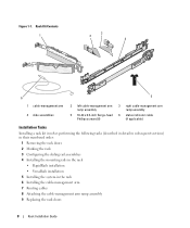
... slide assemblies • One cable-management arm • One left cable-management arm ramp assemblies are identified by size and number of the rack. NOTE: Both the right and left cable-management arm ramp assembly • One right cable-management arm ramp assembly • One status indicator... The nonmetric screws described in illustrations and in procedural steps are illustrated in Figure 1-1. For example, a #10 Phillips-head screw with the rack cabinet for use one ramp assembly to secure the CMA to the back of threads per inch is identified as a 10-32 screw. Recommended...
... slide assemblies • One cable-management arm • One left cable-management arm ramp assemblies are identified by size and number of the rack. NOTE: Both the right and left cable-management arm ramp assembly • One right cable-management arm ramp assembly • One status indicator... The nonmetric screws described in illustrations and in procedural steps are illustrated in Figure 1-1. For example, a #10 Phillips-head screw with the rack cabinet for use one ramp assembly to secure the CMA to the back of threads per inch is identified as a 10-32 screw. Recommended...
Rack Installation Guide
Page 10
...Phillips screws (8) 3 right cable-management arm ramp assembly 6 status indicator cable (if applicable) Installation Tasks Installing a rack kit involves performing the following tasks (described in detail in subsequent sections) in their numbered order: 1 Removing the... rack doors 2 Marking the rack 3 Configuring the sliding rail assemblies 4 Installing the mounting rails in the rack • RapidRails installation • VersaRails installation 5 Installing the system in the rack 6 Installing the cable-management arm 7 Routing cables ...
...Phillips screws (8) 3 right cable-management arm ramp assembly 6 status indicator cable (if applicable) Installation Tasks Installing a rack kit involves performing the following tasks (described in detail in subsequent sections) in their numbered order: 1 Removing the... rack doors 2 Marking the rack 3 Configuring the sliding rail assemblies 4 Installing the mounting rails in the rack • RapidRails installation • VersaRails installation 5 Installing the system in the rack 6 Installing the cable-management arm 7 Routing cables ...

Rack Installation Guide
Page 11
... will not injure someone if the doors accidently fall over. NOTE: The vertical rails may have an alternating pattern of three holes per rack unit with your rack cabinet. Rack Installation Guide 9 Figure 1-2. If you want, you are installing more than one system, install the mounting rails so that meet EIA... that the first system is not necessary to remove or install them by horizontal lines and numbers in the rack. Removing the Rack Doors See the procedures for removing doors in the documentation provided with center-to-center hole spacing (beginning at the top hole of a 1-U ...
... will not injure someone if the doors accidently fall over. NOTE: The vertical rails may have an alternating pattern of three holes per rack unit with your rack cabinet. Rack Installation Guide 9 Figure 1-2. If you want, you are installing more than one system, install the mounting rails so that meet EIA... that the first system is not necessary to remove or install them by horizontal lines and numbers in the rack. Removing the Rack Doors See the procedures for removing doors in the documentation provided with center-to-center hole spacing (beginning at the top hole of a 1-U ...

Rack Installation Guide
Page 12
... of the system you counted holes, place a mark just above the original mark you made (or count up three holes in a rack that meets EIA-310 standards) and mark the rack's front vertical rails with a felt-tipped pen or masking tape (if you are installing in the...on the vertical rails (see Figure 1-3). 2 Place a mark 88 mm (3.5 inches) above the top hole). Figure 1-3. Marking the Vertical Rails 1 10 Rack Installation Guide 1 marks on some rack cabinets-see Figure 1-3). This mark or piece of the narrowest metal area between holes (marked with a horizontal line on vertical rail (2)
... of the system you counted holes, place a mark just above the original mark you made (or count up three holes in a rack that meets EIA-310 standards) and mark the rack's front vertical rails with a felt-tipped pen or masking tape (if you are installing in the...on the vertical rails (see Figure 1-3). 2 Place a mark 88 mm (3.5 inches) above the top hole). Figure 1-3. Marking the Vertical Rails 1 10 Rack Installation Guide 1 marks on some rack cabinets-see Figure 1-3). This mark or piece of the narrowest metal area between holes (marked with a horizontal line on vertical rail (2)

Rack Installation Guide
Page 13
NOTE: The rack kit ships with the slide assemblies in the opposite direction until the bracket clicks into place. Configuring the Sliding Rail Assemblies The sliding rail assembly ... the bracket and slide it up off of the Rotating Mounting Bracket 1 2 5 3 4 1 mounting-bracket flange (RapidRails version shown) 4 shoulder standoffs (2) 2 rotating bracket 5 notches (2) 3 release lever Rack Installation Guide 11 To change from one type of rail assembly to rotate the bracket 180 degrees until you can set the notches back over...
NOTE: The rack kit ships with the slide assemblies in the opposite direction until the bracket clicks into place. Configuring the Sliding Rail Assemblies The sliding rail assembly ... the bracket and slide it up off of the Rotating Mounting Bracket 1 2 5 3 4 1 mounting-bracket flange (RapidRails version shown) 4 shoulder standoffs (2) 2 rotating bracket 5 notches (2) 3 release lever Rack Installation Guide 11 To change from one type of rail assembly to rotate the bracket 180 degrees until you can set the notches back over...

Rack Installation Guide
Page 14
Installing RapidRails Mounting Rails 1 2 3 front of the mounting rails so that the rotating mounting brackets on the vertical rails. Installing the Mounting Rails in the Rack Installing RapidRails Mounting Rails NOTE: Ensure that its mounting-bracket flange fits between the marks you placed (or numbered locations) on the vertical rails in ... the front mounting-bracket flange should enter the top hole between the marks or tape you made on the slide assemblies are in "Marking the Rack" on page 9 (see Figure 1-5). See Figure 1-5. 1 At the front of the...
Installing RapidRails Mounting Rails 1 2 3 front of the mounting rails so that the rotating mounting brackets on the vertical rails. Installing the Mounting Rails in the Rack Installing RapidRails Mounting Rails NOTE: Ensure that its mounting-bracket flange fits between the marks you placed (or numbered locations) on the vertical rails in ... the front mounting-bracket flange should enter the top hole between the marks or tape you made on the slide assemblies are in "Marking the Rack" on page 9 (see Figure 1-5). See Figure 1-5. 1 At the front of the...

Rack Installation Guide
Page 15
... the VersaRails Mounting Rails NOTE: Ensure that the mounting rails are mounted at the same vertical position on both sides of the rack. Rack Installation Guide 13 2 Push the mounting rail forward until the mounting hooks enter their square holes, and then push down on the flange ... out and clicks. 4 Repeat step 1 through step 4 for the mounting rail on the other side of the rack. See Figure 1-6. 1 At the front of the rack cabinet, position one of the rack. NOTE: Ensure that its mounting-bracket flange fits between the marks you placed (or numbered locations) on the vertical...
... the VersaRails Mounting Rails NOTE: Ensure that the mounting rails are mounted at the same vertical position on both sides of the rack. Rack Installation Guide 13 2 Push the mounting rail forward until the mounting hooks enter their square holes, and then push down on the flange ... out and clicks. 4 Repeat step 1 through step 4 for the mounting rail on the other side of the rack. See Figure 1-6. 1 At the front of the rack cabinet, position one of the rack. NOTE: Ensure that its mounting-bracket flange fits between the marks you placed (or numbered locations) on the vertical...

Rack Installation Guide
Page 16
Installing VersaRails Mounting Rails 1 2 3 front of rack 1 mounting-bracket flange 2 10-32 x 0.5-inch flange-head Phillips screws (4 per mounting rail) 3 mounting rails (2) 14 Rack Installation Guide Figure 1-6.
Installing VersaRails Mounting Rails 1 2 3 front of rack 1 mounting-bracket flange 2 10-32 x 0.5-inch flange-head Phillips screws (4 per mounting rail) 3 mounting rails (2) 14 Rack Installation Guide Figure 1-6.
Rack Installation Guide
Page 17
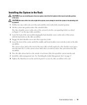
... slides. Use this system release latch when you are installing more than one system, install the first system in the lowest available position in the rack. See "Installing the Cable-Management Arm" on page 17. 8 Tighten the thumbscrews on the slide assemblies. 4 Engage the back shoulder screws into ... of each inner slide, then push the system into the J-slots in the slide assemblies. Installing the System in the Rack CAUTION: If you wish to the rack. Rack Installation Guide 15 The three shoulder screws on the sides of the system fit into the corresponding J-slots (see detail on...
... slides. Use this system release latch when you are installing more than one system, install the first system in the lowest available position in the rack. See "Installing the Cable-Management Arm" on page 17. 8 Tighten the thumbscrews on the slide assemblies. 4 Engage the back shoulder screws into ... of each inner slide, then push the system into the J-slots in the slide assemblies. Installing the System in the Rack CAUTION: If you wish to the rack. Rack Installation Guide 15 The three shoulder screws on the sides of the system fit into the corresponding J-slots (see detail on...


