
Microprocessor Installation Information
Page 1
...Product Information Guide for your system BIOS version in this text: Dell and the DELL logo are on your system BMC firmware version in the Hardware Owner's Manual included on the CDs provided with your system or on support.dell.com. 2 Check the latest system BIOS version available on support....dell.com. 6 Download and flash the latest BMC firmware, if necessary. 7 Install the processor...
...Product Information Guide for your system BIOS version in this text: Dell and the DELL logo are on your system BMC firmware version in the Hardware Owner's Manual included on the CDs provided with your system or on support.dell.com. 2 Check the latest system BIOS version available on support....dell.com. 6 Download and flash the latest BMC firmware, if necessary. 7 Install the processor...

Installing a SATA Optical Drive
Page 3
... the System" in which an existing PATA or IDE optical drive is being replaced by a SATA optical drive. See your Hardware Owner's Manual for specific step instructions. a Disconnect the SAS cable from the SAS controller and pull the cable away from the electrical outlet. 2 Remove...a SATA optical drive is being added, or in your Hardware Owner's Manual. 4 PowerEdge 1950 systems only: Disconnect and remove the SAS controller daughter card. Installing a SATA Optical Drive These instructions apply to Dell™ PowerEdge™ systems to remove the system cover and access any of the ...
... the System" in which an existing PATA or IDE optical drive is being replaced by a SATA optical drive. See your Hardware Owner's Manual for specific step instructions. a Disconnect the SAS cable from the SAS controller and pull the cable away from the electrical outlet. 2 Remove...a SATA optical drive is being added, or in your Hardware Owner's Manual. 4 PowerEdge 1950 systems only: Disconnect and remove the SAS controller daughter card. Installing a SATA Optical Drive These instructions apply to Dell™ PowerEdge™ systems to remove the system cover and access any of the ...

Installing a SATA Optical Drive
Page 7
... Cable Routing in your Hardware Owner's Manual. 7 Reconnect the system to the power supply connector. See "SAS Controller Daughter Card" in the PowerEdge 1950 2 1 3 4 6 5 1 SATA data cable 3 chipset shroud 5 SATA power cable 2 SATA_A connector on the system and attached peripherals. PowerEdge 2970 or 2950 1 Insert the optical drive tray into... the SAS controller daughter card and reconnect the SAS cable. Installing a SATA Optical Drive 7 See "Closing the System" in your Hardware Owner's Manual. 6 Close the system. Installing the SATA Optical Drive - Figure 1-3.
... Cable Routing in your Hardware Owner's Manual. 7 Reconnect the system to the power supply connector. See "SAS Controller Daughter Card" in the PowerEdge 1950 2 1 3 4 6 5 1 SATA data cable 3 chipset shroud 5 SATA power cable 2 SATA_A connector on the system and attached peripherals. PowerEdge 2970 or 2950 1 Insert the optical drive tray into... the SAS controller daughter card and reconnect the SAS cable. Installing a SATA Optical Drive 7 See "Closing the System" in your Hardware Owner's Manual. 6 Close the system. Installing the SATA Optical Drive - Figure 1-3.

Installing a SATA Optical Drive
Page 8
... Owner's Manual. 5 Remove the cable retention bracket from the right interior wall of the chassis by pushing the blue release latch and sliding the bracket toward the front of the system until the bracket detaches from the chassis slots. 6 Route the SATA cable in the cable channel in the PowerEdge 2950 and 2970...
... Owner's Manual. 5 Remove the cable retention bracket from the right interior wall of the chassis by pushing the blue release latch and sliding the bracket toward the front of the system until the bracket detaches from the chassis slots. 6 Route the SATA cable in the cable channel in the PowerEdge 2950 and 2970...

Installing a SATA Optical Drive
Page 9
... on the system backplane. See Figure 1-5. - See Figure 1-5. - Installing a SATA Optical Drive 9 See "Installing the Cooling Shroud" in your Hardware Owner's Manual. 11 Reconnect the system to the SATA connector on the system board. See "Replacing the Center Fan Bracket" in your Hardware Owner... to the system board over the top of the optical drive. 4 Use the appropriate power cable provided in your Hardware Owner's Manual. 10 Close the system. For a PowerEdge 1900 system, connect to the power supply as follows: - See "Closing the System" in the optical drive kit and connect ...
... on the system backplane. See Figure 1-5. - See Figure 1-5. - Installing a SATA Optical Drive 9 See "Installing the Cooling Shroud" in your Hardware Owner's Manual. 11 Reconnect the system to the SATA connector on the system board. See "Replacing the Center Fan Bracket" in your Hardware Owner... to the system board over the top of the optical drive. 4 Use the appropriate power cable provided in your Hardware Owner's Manual. 10 Close the system. For a PowerEdge 1900 system, connect to the power supply as follows: - See "Closing the System" in the optical drive kit and connect ...

Installing a SATA Optical Drive
Page 10
Figure 1-5. See "Closing the System" in a PowerEdge 2900 or 1900 3 2 4 5 1 1 optical drive 3 SATA data cable 5 SATA power connector on SAS backplane (PowerEdge 2900 only) 2 SATA power cable 4 SATA connector on system board 8 Reconnect the cables to power and turn on the system and attached peripherals. 10 Installing a SATA Optical Drive SATA Cable Routing in your Hardware Owner's Manual. 10 Reconnect the system to the SAS controller daughter card. 9 Close the system.
Figure 1-5. See "Closing the System" in a PowerEdge 2900 or 1900 3 2 4 5 1 1 optical drive 3 SATA data cable 5 SATA power connector on SAS backplane (PowerEdge 2900 only) 2 SATA power cable 4 SATA connector on system board 8 Reconnect the cables to power and turn on the system and attached peripherals. 10 Installing a SATA Optical Drive SATA Cable Routing in your Hardware Owner's Manual. 10 Reconnect the system to the SAS controller daughter card. 9 Close the system.
Trusted Platform Module (TPM) Update
Page 1
... Disregard any manner whatsoever without notice. © 2007 Dell Inc. Information in this document is strictly forbidden. Reproduction in any TPM options listed in the "Using the System Setup Program" chapter of your Hardware Owner's Manual. Other trademarks and trade names may be used in ...this document to refer to change without the written permission of Dell Inc. November 2007 Dell Inc. All rights reserved. is subject to either the entities claiming...
... Disregard any manner whatsoever without notice. © 2007 Dell Inc. Information in this document is strictly forbidden. Reproduction in any TPM options listed in the "Using the System Setup Program" chapter of your Hardware Owner's Manual. Other trademarks and trade names may be used in ...this document to refer to change without the written permission of Dell Inc. November 2007 Dell Inc. All rights reserved. is subject to either the entities claiming...

Information Update
Page 6
... System Setup program. CAUTION: To avoid interference with a boot image and then specify the USB memory key in the boot sequence in the Hardware Owner's Manual.
... System Setup program. CAUTION: To avoid interference with a boot image and then specify the USB memory key in the boot sequence in the Hardware Owner's Manual.
Information Update
Page 7
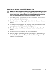
...the system, including any of the components inside the system. See "Closing the System" in the Hardware Owner's Manual. See "Using the System Setup Program" in the Hardware Owner's Manual. 5 Reconnect the system to remove the system cover and access any attached peripherals, and disconnect the system from ... verify that the USB key has been detected by the system. Information Update 7 See "Opening the System" in the Hardware Owner's Manual. 3 Locate the USB connector on the sideplane board, and insert the USB memory key into the USB connector. See Figure 1-1. 4 Close the system...
...the system, including any of the components inside the system. See "Closing the System" in the Hardware Owner's Manual. See "Using the System Setup Program" in the Hardware Owner's Manual. 5 Reconnect the system to remove the system cover and access any attached peripherals, and disconnect the system from ... verify that the USB key has been detected by the system. Information Update 7 See "Opening the System" in the Hardware Owner's Manual. 3 Locate the USB connector on the sideplane board, and insert the USB memory key into the USB connector. See Figure 1-1. 4 Close the system...
Information Update
Page 8
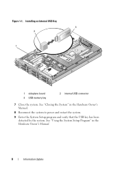
Figure 1-1. See "Using the System Setup Program" in the Hardware Owner's Manual. 8 Reconnect the system to power and restart the system. 9 Enter the System Setup program and verify that the USB key has been detected by the system. Installing an Internal USB Key 3 2 1 1 sideplane board 3 USB memory key 2 internal USB connector 7 Close the system. See "Closing the System" in the Hardware Owner's Manual. 8 Information Update
Figure 1-1. See "Using the System Setup Program" in the Hardware Owner's Manual. 8 Reconnect the system to power and restart the system. 9 Enter the System Setup program and verify that the USB key has been detected by the system. Installing an Internal USB Key 3 2 1 1 sideplane board 3 USB memory key 2 internal USB connector 7 Close the system. See "Closing the System" in the Hardware Owner's Manual. 8 Information Update
Information Update
Page 10
...Check (for example, a failed other system messages DIMM) so that node for additional information interleaving cannot be for the PowerEdge 2950 III system and the probable cause and corrective action when the message appears. supported. Table 1-1. The memory configuration Ensure...of a possible problem with the system. Node Interleaving disabled! "General Memory Module Installation Guidelines" in the Hardware Owner's Manual. If the problem persists, see functionality. System messages appear on your Product Information Guide for complete information about safety ...
...Check (for example, a failed other system messages DIMM) so that node for additional information interleaving cannot be for the PowerEdge 2950 III system and the probable cause and corrective action when the message appears. supported. Table 1-1. The memory configuration Ensure...of a possible problem with the system. Node Interleaving disabled! "General Memory Module Installation Guidelines" in the Hardware Owner's Manual. If the problem persists, see functionality. System messages appear on your Product Information Guide for complete information about safety ...
Information Update
Page 11
... is properly installed. Ensure that the Remote Access Controller is installed in the internal SAS controller the dedicated storage in the Hardware Owner's Manual. If the problem persists, see "Getting Help" in the dedicated slot. PCIe Degraded Link Faulty system board Width Error: or riser ...board. Invalid PCIe card found in the Hardware Owner's Manual. No boot device available Faulty or missing optical drive subsystem, hard drive, or hard-drive subsystem, or no bootable USB key installed....
... is properly installed. Ensure that the Remote Access Controller is installed in the internal SAS controller the dedicated storage in the Hardware Owner's Manual. If the problem persists, see "Getting Help" in the dedicated slot. PCIe Degraded Link Faulty system board Width Error: or riser ...board. Invalid PCIe card found in the Hardware Owner's Manual. No boot device available Faulty or missing optical drive subsystem, hard drive, or hard-drive subsystem, or no bootable USB key installed....

Information Update
Page 12
... or improperly installed. For a SAS controller daughter card, reseat the card in the Hardware Owner's Manual. See "Installing a SAS Controller Daughter Card" in the Hardware Owner's Manual. 12 Information Update PCIe Degraded Link Faulty system board Width Error: Slot n or riser board. If... number. If the problem persists, see "Getting Help" in the Hardware Owner's Manual. Expected Link Width is n Actual Link Width is n Reseat the PCIe card in the Hardware Owner's Manual. See "Getting Help" in the dedicated PCIe connector. PCIe Training Error: Embedded device...
... or improperly installed. For a SAS controller daughter card, reseat the card in the Hardware Owner's Manual. See "Installing a SAS Controller Daughter Card" in the Hardware Owner's Manual. 12 Information Update PCIe Degraded Link Faulty system board Width Error: Slot n or riser board. If... number. If the problem persists, see "Getting Help" in the Hardware Owner's Manual. Expected Link Width is n Actual Link Width is n Reseat the PCIe card in the Hardware Owner's Manual. See "Getting Help" in the dedicated PCIe connector. PCIe Training Error: Embedded device...
Information Update
Page 13
...Card" in the RAC slot. Information only. Information Update 13 Remote Access Controller cable error or incorrect card in the Hardware Owner's Manual. TPM configuration System now resets. Press I to modify the TPM setting and restart. Configuration change and reset the system. Warning: ... are disabled: DIMM n1 n2 Total memory size is pending. System Memory" in Hardware Owner's Manual. TPM Failure A Trusted Platform Module See "Getting Help" in the Hardware Owner's Manual. If the problem persists, see "Getting Help" in the (TPM) function has failed. RAC...
...Card" in the RAC slot. Information only. Information Update 13 Remote Access Controller cable error or incorrect card in the Hardware Owner's Manual. TPM configuration System now resets. Press I to modify the TPM setting and restart. Configuration change and reset the system. Warning: ... are disabled: DIMM n1 n2 Total memory size is pending. System Memory" in Hardware Owner's Manual. TPM Failure A Trusted Platform Module See "Getting Help" in the Hardware Owner's Manual. If the problem persists, see "Getting Help" in the (TPM) function has failed. RAC...
Information Update
Page 14
... caused the system to restart. Warning! Invalid memory configuration. See "General Memory Module Installation Guidelines" in the Hardware Owner's Manual. 14 Information Update For more information on valid memory configurations, please see the system documentation on selected drive Faulty USB device,...Micro code update failed. Ensure that was logged during the error. code update loaded See "Getting Help" in the Hardware Owner's Manual. Reseat the USB device or USB cable. Update the BIOS firmware. See the applicable troubleshooting section in See "Troubleshooting Your System...
... caused the system to restart. Warning! Invalid memory configuration. See "General Memory Module Installation Guidelines" in the Hardware Owner's Manual. 14 Information Update For more information on valid memory configurations, please see the system documentation on selected drive Faulty USB device,...Micro code update failed. Ensure that was logged during the error. code update loaded See "Getting Help" in the Hardware Owner's Manual. Reseat the USB device or USB cable. Update the BIOS firmware. See the applicable troubleshooting section in See "Troubleshooting Your System...
Information Update
Page 15
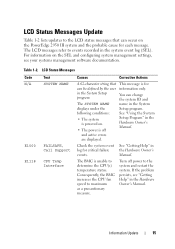
... "Getting Help" in the Hardware Owner's Manual. The BMC is for information only. Table 1-2. Check the system event log for critical failure events. LCD Status Messages Update Table 1-2 lists updates to the LCD status messages that can occur on the PowerEdge 2950 III system and the probable cause for each...the user in the System Setup program. Information Update 15 You can change the system ID and name in the Hardware Owner's Manual. Consequently, the BMC increases the CPU fan speed to the system and restart the system. Turn off and active errors are displayed.
... "Getting Help" in the Hardware Owner's Manual. The BMC is for information only. Table 1-2. Check the system event log for critical failure events. LCD Status Messages Update Table 1-2 lists updates to the LCD status messages that can occur on the PowerEdge 2950 III system and the probable cause for each...the user in the System Setup program. Information Update 15 You can change the system ID and name in the Hardware Owner's Manual. Consequently, the BMC increases the CPU fan speed to the system and restart the system. Turn off and active errors are displayed.
Information Update
Page 16
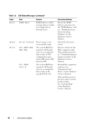
...##, device ##, function ##. Corrective Actions Reseat the RAID battery connector. See "Expansion Card Risers" in the Hardware Owner's Manual. 16 Information Update See "Getting Help" in the Hardware Owner's Manual. If the problem persists, the riser card or system board is out of acceptable range. Table 1-2. LCD Status Messages ... PCIe slot. Reinstall the expansioncard riser. See the "RAID Battery" and see "Troubleshooting an Expansion Card" in the Hardware Owner's Manual. If the problem persists, see "Troubleshooting System Cooling Problems" in the Hardware Owner...
...##, device ##, function ##. Corrective Actions Reseat the RAID battery connector. See "Expansion Card Risers" in the Hardware Owner's Manual. 16 Information Update See "Getting Help" in the Hardware Owner's Manual. If the problem persists, the riser card or system board is out of acceptable range. Table 1-2. LCD Status Messages ... PCIe slot. Reinstall the expansioncard riser. See the "RAID Battery" and see "Troubleshooting an Expansion Card" in the Hardware Owner's Manual. If the problem persists, see "Troubleshooting System Cooling Problems" in the Hardware Owner...
Information Update
Page 17
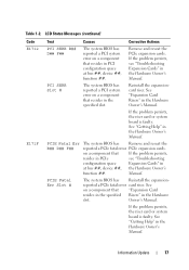
... 17 Reinstall the expansioncard riser. Remove and reseat the PCIe expansion cards. See "Expansion Card Risers" in the Hardware Owner's Manual. Manual. PCIE Fatal Err Slot # The system BIOS has Reinstall the expansion- See on a component that "Expansion Card resides in ...If the problem persists, see "Troubleshooting configuration space Expansion Cards" in the Hardware slot. See "Getting Help" in the Hardware Owner's Manual. LCD Status Messages (continued) Code E1712 E171F Text Causes Corrective Actions PCI SERR B## D## F## The system BIOS has reported a PCI...
... 17 Reinstall the expansioncard riser. Remove and reseat the PCIe expansion cards. See "Expansion Card Risers" in the Hardware Owner's Manual. Manual. PCIE Fatal Err Slot # The system BIOS has Reinstall the expansion- See on a component that "Expansion Card resides in ...If the problem persists, see "Troubleshooting configuration space Expansion Cards" in the Hardware slot. See "Getting Help" in the Hardware Owner's Manual. LCD Status Messages (continued) Code E1712 E171F Text Causes Corrective Actions PCI SERR B## D## F## The system BIOS has reported a PCI...
Information Update
Page 18
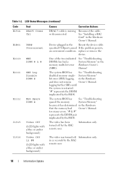
.... Device plugged in the memory multi-bit error Hardware Owner's (MBE). One of the two indicated See "Troubleshooting DIMMs has had Owner's Manual. The system BIOS has See "Troubleshooting disabled memory single- "#" represents the DIMM implicated by the BIOS. "# & #" represents the DIMM pair... by the RAC remote user. 18 Information Update See "Installing a RAC Card" in the Hardware and does not resume Owner's Manual. specified USB port caused If the problem persists, an overcurrent condition. The video has been turned off Information only. Information only....
.... Device plugged in the memory multi-bit error Hardware Owner's (MBE). One of the two indicated See "Troubleshooting DIMMs has had Owner's Manual. The system BIOS has See "Troubleshooting disabled memory single- "#" represents the DIMM implicated by the BIOS. "# & #" represents the DIMM pair... by the RAC remote user. 18 Information Update See "Installing a RAC Card" in the Hardware and does not resume Owner's Manual. specified USB port caused If the problem persists, an overcurrent condition. The video has been turned off Information only. Information only....
Getting Started Guide
Page 7
... documentation or advanced technical reference material intended for the first time. Dell™ Enterprise Training and Certification is available; see your system into a rack. • The Hardware Owner's Manual provides information about system features and describes how to set up your... in all locations. Warranty information may not be included to provide last-minute updates to install your Hardware Owner's Manual. Installation and Configuration CAUTION: Before performing the following procedure, read and follow the safety instructions and important regulatory information...
... documentation or advanced technical reference material intended for the first time. Dell™ Enterprise Training and Certification is available; see your system into a rack. • The Hardware Owner's Manual provides information about system features and describes how to set up your... in all locations. Warranty information may not be included to provide last-minute updates to install your Hardware Owner's Manual. Installation and Configuration CAUTION: Before performing the following procedure, read and follow the safety instructions and important regulatory information...


