
Installing a SATA Optical Drive
Page 6
... system board. a Route the cable through the power cable cutout in a PowerEdge 1950 Drive Tray 2 3 1 4 5 1 optical drive 3 SATA power cable 5 optical drive carrier 2 SATA cable 4 carrier latch Installing the SATA Optical Drive - Installing a SATA Optical Drive in the fan bracket and follow the power cable routing to the power supply connector. See Figure 1-3. c Connect the cable...
... system board. a Route the cable through the power cable cutout in a PowerEdge 1950 Drive Tray 2 3 1 4 5 1 optical drive 3 SATA power cable 5 optical drive carrier 2 SATA cable 4 carrier latch Installing the SATA Optical Drive - Installing a SATA Optical Drive in the fan bracket and follow the power cable routing to the power supply connector. See Figure 1-3. c Connect the cable...

Installing a SATA Optical Drive
Page 7
...Manual. 7 Reconnect the system to the power supply connector. See "SAS Controller Daughter Card" in the PowerEdge 1950 2 1 3 4 6 5 1 SATA data cable 3 chipset shroud 5 SATA power cable 2 SATA_A connector on the system and attached peripherals. Installing a SATA Optical Drive 7 PowerEdge 2970 or 2950 1 Insert the optical... drive tray into the system until it is fully inserted and locked into position. 2 Connect the SATA cable (the end with the branching power cable) to the back of the optical...
...Manual. 7 Reconnect the system to the power supply connector. See "SAS Controller Daughter Card" in the PowerEdge 1950 2 1 3 4 6 5 1 SATA data cable 3 chipset shroud 5 SATA power cable 2 SATA_A connector on the system and attached peripherals. Installing a SATA Optical Drive 7 PowerEdge 2970 or 2950 1 Insert the optical... drive tray into the system until it is fully inserted and locked into position. 2 Connect the SATA cable (the end with the branching power cable) to the back of the optical...

Installing a SATA Optical Drive
Page 9
... other to an available power supply cable. 5 Replace the center fan bracket. For a PowerEdge 2900, use the SATA_D connector. See Figure 1-5. - For a PowerEdge 1900, use the SATA_B connector. - For a PowerEdge 2900 system, connect to power and turn on the system and attached peripherals. PowerEdge 2900 and 1900 1 If ...the back of the fan bracket and connect the cable to the SATA connector on the system backplane. For a PowerEdge 1900 system, connect to the power supply as follows: - See "Installing the Cooling Shroud" in your Hardware Owner's Manual. 10 Close the system....
... other to an available power supply cable. 5 Replace the center fan bracket. For a PowerEdge 2900, use the SATA_D connector. See Figure 1-5. - For a PowerEdge 1900, use the SATA_B connector. - For a PowerEdge 2900 system, connect to power and turn on the system and attached peripherals. PowerEdge 2900 and 1900 1 If ...the back of the fan bracket and connect the cable to the SATA connector on the system backplane. For a PowerEdge 1900 system, connect to the power supply as follows: - See "Installing the Cooling Shroud" in your Hardware Owner's Manual. 10 Close the system....
Getting Started Guide
Page 5
...must use an operating system that signals the appropriate systems management software if the top cover is opened. • Up to two hot-pluggable, 930-W power supplies in a 1 + 1 redundant configuration. • Six hot-pluggable system cooling fans. Not all versions of 48 GB by dividing processor operations between ... combinations of the processor, heat sink, and fan as well as additional processors. NOTE: If you must order the processor upgrade kits from Dell contains the correct version of 256-MB, 512-MB, 1-GB, 2-GB, or 4-GB memory modules in the twelve memory module sockets on...
...must use an operating system that signals the appropriate systems management software if the top cover is opened. • Up to two hot-pluggable, 930-W power supplies in a 1 + 1 redundant configuration. • Six hot-pluggable system cooling fans. Not all versions of 48 GB by dividing processor operations between ... combinations of the processor, heat sink, and fan as well as additional processors. NOTE: If you must order the processor upgrade kits from Dell contains the correct version of 256-MB, 512-MB, 1-GB, 2-GB, or 4-GB memory modules in the twelve memory module sockets on...

Getting Started Guide
Page 9
Getting Started With Your System 7 Connecting the Keyboard, Mouse, and Monitor Connect the keyboard, mouse, and monitor (optional). The connectors on the monitor's cable connector. Plug the other end of your system have icons indicating which cable to the system. Connecting the Power Connect the system's power cable(s) to plug into a grounded electrical outlet or a separate power source such as an uninterrupted power supply (UPS) or a power distribution unit (PDU). Be sure to tighten the screws (if any) on the back of the cable into each connector.
Getting Started With Your System 7 Connecting the Keyboard, Mouse, and Monitor Connect the keyboard, mouse, and monitor (optional). The connectors on the monitor's cable connector. Plug the other end of your system have icons indicating which cable to the system. Connecting the Power Connect the system's power cable(s) to plug into a grounded electrical outlet or a separate power source such as an uninterrupted power supply (UPS) or a power distribution unit (PDU). Be sure to tighten the screws (if any) on the back of the cable into each connector.

Getting Started Guide
Page 10
Installing the Power Cord Retention Bracket Attach the power cord retention bracket on the system and monitor (optional). Turning on the System Turn on the right bend of the power supply handle. The power indicators should light. Press the power button on the system and the monitor. Adjust the monitor's controls until the displayed image is satisfactory. 8 Getting Started With Your System Bend the system power cable into a loop as shown in the illustration and attach to the bracket's cable clasp. Repeat the procedure for the second power supply.
Installing the Power Cord Retention Bracket Attach the power cord retention bracket on the system and monitor (optional). Turning on the System Turn on the right bend of the power supply handle. The power indicators should light. Press the power button on the system and the monitor. Adjust the monitor's controls until the displayed image is satisfactory. 8 Getting Started With Your System Bend the system power cable into a loop as shown in the illustration and attach to the bracket's cable clasp. Repeat the procedure for the second power supply.

Getting Started Guide
Page 13
...BTU/hr maximum Under typical line conditions and over the entire system ambient operating range, the inrush current may reach 55 A per power supply) Wattage Voltage Heat dissipation Maximum inrush current Batteries System battery RAID battery (optional) Physical Rack Height Width Two TOE-capable RJ-45...) with rack flanges Getting Started With Your System 11 Connectors Back NIC Serial USB Video Front Video USB Video Video type Video memory Power AC power supply (per power supply for integrated 1-GB NICs) 9-pin, DTE, 16550-compatible Four 4-pin, USB 2.0-compliant 15-pin VGA 15-pin VGA Two 4-...
...BTU/hr maximum Under typical line conditions and over the entire system ambient operating range, the inrush current may reach 55 A per power supply) Wattage Voltage Heat dissipation Maximum inrush current Batteries System battery RAID battery (optional) Physical Rack Height Width Two TOE-capable RJ-45...) with rack flanges Getting Started With Your System 11 Connectors Back NIC Serial USB Video Front Video USB Video Video type Video memory Power AC power supply (per power supply for integrated 1-GB NICs) 9-pin, DTE, 16550-compatible Four 4-pin, USB 2.0-compliant 15-pin VGA 15-pin VGA Two 4-...
Hardware Owner's Manual (PDF)
Page 4
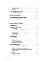
... Drive Carrier 58 Installing a SATA Hard Drive Into a SATA Drive Carrier 59 Installing a SATA Hard Drive and Interposer Card Into a SATAu Hard-Drive Carrier 60 Power Supplies 62 Removing a Power Supply 62 Installing a Power Supply 63 4 Contents
... Drive Carrier 58 Installing a SATA Hard Drive Into a SATA Drive Carrier 59 Installing a SATA Hard Drive and Interposer Card Into a SATAu Hard-Drive Carrier 60 Power Supplies 62 Removing a Power Supply 62 Installing a Power Supply 63 4 Contents

Hardware Owner's Manual (PDF)
Page 5
Removing the Power Supply Blank 64 Installing the Power Supply Blank 64 Fans 64 Removing and Installing a Fan 65 Removing or Installing the Cooling Shroud Fan 66 Expansion Cards 68 Installing an Expansion Card 68 ...
Removing the Power Supply Blank 64 Installing the Power Supply Blank 64 Fans 64 Removing and Installing a Fan 65 Removing or Installing the Cooling Shroud Fan 66 Expansion Cards 68 Installing an Expansion Card 68 ...

Hardware Owner's Manual (PDF)
Page 7
... Troubleshooting a Serial I/O Device 119 Troubleshooting a USB Device 119 Troubleshooting a NIC 120 Troubleshooting a Wet System 120 Troubleshooting a Damaged System 121 Troubleshooting the System Battery 122 Troubleshooting Power Supplies 122 Troubleshooting System Cooling Problems 123 Troubleshooting a Fan 123 Troubleshooting System Memory 124 Troubleshooting a Diskette Drive 126 Troubleshooting an Optical Drive 127 Troubleshooting an External...
... Troubleshooting a Serial I/O Device 119 Troubleshooting a USB Device 119 Troubleshooting a NIC 120 Troubleshooting a Wet System 120 Troubleshooting a Damaged System 121 Troubleshooting the System Battery 122 Troubleshooting Power Supplies 122 Troubleshooting System Cooling Problems 123 Troubleshooting a Fan 123 Troubleshooting System Memory 124 Troubleshooting a Diskette Drive 126 Troubleshooting an Optical Drive 127 Troubleshooting an External...

Hardware Owner's Manual (PDF)
Page 12
..., and connectors located behind the optional rack bezel on . Front-Panel Features and Indicators 1 2 34 5 6 7 8 11 Table 1-2. The power button controls the DC power supply output to troubleshoot software and device driver errors when using certain operating systems. This button can be pressed using the... power button and the system is running an ACPI-compliant operating system, the power is turned off . If the system is...
..., and connectors located behind the optional rack bezel on . Front-Panel Features and Indicators 1 2 34 5 6 7 8 11 Table 1-2. The power button controls the DC power supply output to troubleshoot software and device driver errors when using certain operating systems. This button can be pressed using the... power button and the system is running an ACPI-compliant operating system, the power is turned off . If the system is...

Hardware Owner's Manual (PDF)
Page 16
... 11 10 9 8 1 serial connector 4 NIC1 connector 7 expansion-card slots (6) 10 system status indicator connector 13 power supply 1 2 video connector 5 NIC2 connector 8 system status indicator 11 power supply 2 (optional) 3 USB connectors (4) 6 remote access connector (optional) 9 system identification button 12 power supply status indicators Connecting External Devices When connecting external devices to your system, follow these guidelines: •...
... 11 10 9 8 1 serial connector 4 NIC1 connector 7 expansion-card slots (6) 10 system status indicator connector 13 power supply 1 2 video connector 5 NIC2 connector 8 system status indicator 11 power supply 2 (optional) 3 USB connectors (4) 6 remote access connector (optional) 9 system identification button 12 power supply status indicators Connecting External Devices When connecting external devices to your system, follow these guidelines: •...

Hardware Owner's Manual (PDF)
Page 17
... Power Supply Indicators Indicator Function Power supply status Green indicates that a valid AC source is connected to the system's power supplies. AC line status Green indicates that the power supply is operational. See "Using the System Setup Program" on the optional redundant power supplies show whether power is present or whether a power fault has occurred (see Table 1-4 and Figure 1-5). Redundant Power Supply Indicators 1 2 3 1 power supply status 2 power supply...
... Power Supply Indicators Indicator Function Power supply status Green indicates that a valid AC source is connected to the system's power supplies. AC line status Green indicates that the power supply is operational. See "Using the System Setup Program" on the optional redundant power supplies show whether power is present or whether a power fault has occurred (see Table 1-4 and Figure 1-5). Redundant Power Supply Indicators 1 2 3 1 power supply status 2 power supply...
Hardware Owner's Manual (PDF)
Page 21
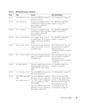
... system BIOS has reported an See "Getting Help" on page 147. specified power supply is available from the specified power supply; PS # Input Range Power source for specified power supply is out of acceptable range Check the AC power source for the specified power supply. If the last Supplies" on page 122. Remove and reseat the PCI expansion cards. See "Troubleshooting...
... system BIOS has reported an See "Getting Help" on page 147. specified power supply is available from the specified power supply; PS # Input Range Power source for specified power supply is out of acceptable range Check the AC power source for the specified power supply. If the last Supplies" on page 122. Remove and reseat the PCI expansion cards. See "Troubleshooting...

Hardware Owner's Manual (PDF)
Page 26
...about safety precautions, working inside the system. In contrast, you know that the problem is easily corrected. wait approximately ten seconds, reconnect the power cable, and restart the system. Either of a possible problem with sensors, such as temperature, voltage, fans, and so on the screen ...Messages For faults associated with the system. You perform this task from the LCD. Table 1-7 lists the system messages that is a failing power supply. CAUTION: Only trained service technicians are authorized to the same display entry. The code on the status LCD, locate the code in a...
...about safety precautions, working inside the system. In contrast, you know that the problem is easily corrected. wait approximately ten seconds, reconnect the power cable, and restart the system. Either of a possible problem with sensors, such as temperature, voltage, fans, and so on the screen ...Messages For faults associated with the system. You perform this task from the LCD. Table 1-7 lists the system messages that is a failing power supply. CAUTION: Only trained service technicians are authorized to the same display entry. The code on the status LCD, locate the code in a...

Hardware Owner's Manual (PDF)
Page 49
Installing System Components This section describes how to install the following system components: • Hot-plug hard drives • Power supplies • Cooling fans • Expansion cards • Tape, optical, and diskette drives • System battery • System memory ...card • Microprocessors • SAS backplane board • SAS controller daughter card • Control panel assembly • System board • Power distribution board Recommended Tools You may need the following items to perform the procedures in this section: • Keys to the system keylocks •...
Installing System Components This section describes how to install the following system components: • Hot-plug hard drives • Power supplies • Cooling fans • Expansion cards • Tape, optical, and diskette drives • System battery • System memory ...card • Microprocessors • SAS backplane board • SAS controller daughter card • Control panel assembly • System board • Power distribution board Recommended Tools You may need the following items to perform the procedures in this section: • Keys to the system keylocks •...
Hardware Owner's Manual (PDF)
Page 53
... discharge. To avoid injury, do not attempt to lift the system by yourself. 1 Unless you are installing a hot-plug component such as a cooling fan or power supply, turn the latch release lock on the cover latch counterclockwise to the unlocked position. See Figure 3-4. 3 Push the latch down to lever the cover into...
... discharge. To avoid injury, do not attempt to lift the system by yourself. 1 Unless you are installing a hot-plug component such as a cooling fan or power supply, turn the latch release lock on the cover latch counterclockwise to the unlocked position. See Figure 3-4. 3 Push the latch down to lever the cover into...

Hardware Owner's Manual (PDF)
Page 62
... in a non-redundant configuration. Remove and replace only one power supply is powered on the left power supply bay (1). NOTE: On a rack system, you can leave the system running and proceed to the next step. 2 Disconnect the power supply power cable from the power source. 3 Disconnect the power cable from the power supply and remove the cable from the cable retention bracket...
... in a non-redundant configuration. Remove and replace only one power supply is powered on the left power supply bay (1). NOTE: On a rack system, you can leave the system running and proceed to the next step. 2 Disconnect the power supply power cable from the power source. 3 Disconnect the power cable from the power supply and remove the cable from the cable retention bracket...

Hardware Owner's Manual (PDF)
Page 63
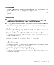
... the new power supply into place. 4 Connect the power cable to the power supply and the power outlet. NOTICE: On a rack system, you are adding a second power supply, remove the power supply blank. The power-supply status indicator turns green to recognize the power supply and determine its...For information about the cable management arm, see Figure 1-5). Installing and Removing a Power Supply 1 3 2 4 6 5 1 power supply 4 power supply blank 2 handle 5 screw 3 tab 6 locking tab Installing a Power Supply 1 If you may need to the cable retention bracket just past the loop....
... the new power supply into place. 4 Connect the power cable to the power supply and the power outlet. NOTICE: On a rack system, you are adding a second power supply, remove the power supply blank. The power-supply status indicator turns green to recognize the power supply and determine its...For information about the cable management arm, see Figure 1-5). Installing and Removing a Power Supply 1 3 2 4 6 5 1 power supply 4 power supply blank 2 handle 5 screw 3 tab 6 locking tab Installing a Power Supply 1 If you may need to the cable retention bracket just past the loop....
Hardware Owner's Manual (PDF)
Page 64
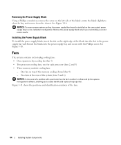
...One fan on top of a problem with the Phillips screw. Rotate the blank into the slot in a non-redundant configuration. Remove the power supply blank only if you to clear the bay, and remove from the chassis. Fans The system contains six hot-plug cooling fans: •... to easily identify and replace the proper fan. NOTICE: To ensure proper system cooling, the power supply blank must be installed on the unoccupied power supply bay in the power supply bay wall. Removing the Power Supply Blank Using a Phillips screwdriver, remove the screw on the left side of the fans. 64...
...One fan on top of a problem with the Phillips screw. Rotate the blank into the slot in a non-redundant configuration. Remove the power supply blank only if you to clear the bay, and remove from the chassis. Fans The system contains six hot-plug cooling fans: •... to easily identify and replace the proper fan. NOTICE: To ensure proper system cooling, the power supply blank must be installed on the unoccupied power supply bay in the power supply bay wall. Removing the Power Supply Blank Using a Phillips screwdriver, remove the screw on the left side of the fans. 64...


