
Installing a Fifth SCSI Hard-Disk Drive
Page 3
... Before installing a fifth SCSI hard-disk drive, you must install a second, optional SCSI backplane daughter card in your system. (For more information about the daughter card, see "Installing Hard-Disk Drives" in a split 1 x 2 and 1 x 3 configuration, you should install and configure the other four SCSI drives. If you want to set up the five drives in your Dell™ system's peripheral bay. SCSI backplane board power supply distribution board SCSI hard-disk drives (4) SCSI ID 0 SCSI ID 1 SCSI ID 2 SCSI ID 3 SCSI interface cable connection for fifth hard-disk drive interposer board...
... Before installing a fifth SCSI hard-disk drive, you must install a second, optional SCSI backplane daughter card in your system. (For more information about the daughter card, see "Installing Hard-Disk Drives" in a split 1 x 2 and 1 x 3 configuration, you should install and configure the other four SCSI drives. If you want to set up the five drives in your Dell™ system's peripheral bay. SCSI backplane board power supply distribution board SCSI hard-disk drives (4) SCSI ID 0 SCSI ID 1 SCSI ID 2 SCSI ID 3 SCSI interface cable connection for fifth hard-disk drive interposer board...

Installing a Fifth SCSI Hard-Disk Drive
Page 4
... | support.dell.com Hard-Disk Drive Configuration The four hard-disk drives connected to the main SCSI backplane board are designated as SCSI ID 4. You can also configure the five drives in the hard-disk drive bays. The fifth hard-disk drive is installed, remove it from the drive. 5 Disconnect all cables connected to the interposer board on the SCSI backplane board. You then reinstall this mode, the host adapter attached to connector SCSIB on the backplane controls slots SCSI ID 0 and SCSI ID 1, while the host adapter connected to connector SCSIA controls slots SCSI...
... | support.dell.com Hard-Disk Drive Configuration The four hard-disk drives connected to the main SCSI backplane board are designated as SCSI ID 4. You can also configure the five drives in the hard-disk drive bays. The fifth hard-disk drive is installed, remove it from the drive. 5 Disconnect all cables connected to the interposer board on the SCSI backplane board. You then reinstall this mode, the host adapter attached to connector SCSIB on the backplane controls slots SCSI ID 0 and SCSI ID 1, while the host adapter connected to connector SCSIA controls slots SCSI...
Installing a Fifth SCSI Hard-Disk Drive
Page 5
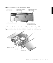
Figure 1-3. Connectors on the Interposer Board cooling fan wiring harness connector system board interface cable connector interposer board power cable connector control panel cable connector diskette drive/CD-ROM drive interface connector 6 Loosen the thumbscrew at the back corner of the peripheral bay (see Figure 1-3). Figure 1-2. Installing the Hard-Disk Drive Cage in the Peripheral Bay thumbscrew hard-disk drive cage rails (2) peripheral bay Installing a Fifth SCSI Hard-Disk Drive 1-3
Figure 1-3. Connectors on the Interposer Board cooling fan wiring harness connector system board interface cable connector interposer board power cable connector control panel cable connector diskette drive/CD-ROM drive interface connector 6 Loosen the thumbscrew at the back corner of the peripheral bay (see Figure 1-3). Figure 1-2. Installing the Hard-Disk Drive Cage in the Peripheral Bay thumbscrew hard-disk drive cage rails (2) peripheral bay Installing a Fifth SCSI Hard-Disk Drive 1-3

Installing a Fifth SCSI Hard-Disk Drive
Page 6
... the insert from the chassis. 10 If a tape drive or other drive is installed in the peripheral bay, release the drive by tightening the thumbscrew at the back of the bay. 11 Slide the hard-disk drive cage into the peripheral bay until the rails snap into place (see Figure 1-4). Be careful to the SCSI cable connector on the Fifth-Drive Backplane Board SCSI cable connector power connector interface cable connector 1-4 Installing a Fifth SCSI Hard-Disk Drive Figure 1-4.
... the insert from the chassis. 10 If a tape drive or other drive is installed in the peripheral bay, release the drive by tightening the thumbscrew at the back of the bay. 11 Slide the hard-disk drive cage into the peripheral bay until the rails snap into place (see Figure 1-4). Be careful to the SCSI cable connector on the Fifth-Drive Backplane Board SCSI cable connector power connector interface cable connector 1-4 Installing a Fifth SCSI Hard-Disk Drive Figure 1-4.

Installing a Fifth SCSI Hard-Disk Drive
Page 7
...data cable connector (PLANAR) SCSI cable connector (SCSIB) data cable connector to optional fifth drive board (DRIVE5) 17 Connect the spare power cable leading from the power supply distribution board (see Figure 1-1) to the power connector on the fifth-drive backplane board (see Figure 1-4). 18 Reconnect the control panel cable, power cable, cooling fan wiring harness, and interposer board interface cable to the interposer board (see Figure 1-2). 19 Install the fifth hard-disk drive by aligning the edge of the hard-disk drive carrier with the opening in your drive upgrade kit to connector...
...data cable connector (PLANAR) SCSI cable connector (SCSIB) data cable connector to optional fifth drive board (DRIVE5) 17 Connect the spare power cable leading from the power supply distribution board (see Figure 1-1) to the power connector on the fifth-drive backplane board (see Figure 1-4). 18 Reconnect the control panel cable, power cable, cooling fan wiring harness, and interposer board interface cable to the interposer board (see Figure 1-2). 19 Install the fifth hard-disk drive by aligning the edge of the hard-disk drive carrier with the opening in your drive upgrade kit to connector...

Installing a Fifth SCSI Hard-Disk Drive
Page 8
www.dell.com | support.dell.com Figure 1-6. SCSI Hard-Disk Drive Carrier hard-disk drive carrier hard-disk drive carrier handle 20 Close the hard-disk drive carrier handle to test the drive. For more information, see "Running the Dell Diagnostics" in place (see Figure 1-6). 21 Check all system cable connections that they do not catch on the system covers or block the airflow of the fans or cooling vents. 22 Close the system covers. 23 Reconnect the...
www.dell.com | support.dell.com Figure 1-6. SCSI Hard-Disk Drive Carrier hard-disk drive carrier hard-disk drive carrier handle 20 Close the hard-disk drive carrier handle to test the drive. For more information, see "Running the Dell Diagnostics" in place (see Figure 1-6). 21 Check all system cable connections that they do not catch on the system covers or block the airflow of the fans or cooling vents. 22 Close the system covers. 23 Reconnect the...

SCSI Backplane Daughter Card
Page 3
... operate your system's SCSI hard-disk drives in your System Information document. 1 Turn off the computer and disconnect it from the electrical outlet. Figure 1-1 shows the location of your system's hard-disk drive bays. Figure 1-1. Basic SCSI Hard-Disk Drive System Components SCSI backplane board data cable SCSI backplane board interface cable SCSI backplane board SCSI hard-disk drives (4) SCSI interface connector SCSIA SCSI ID 0 SCSI ID 1 SCSI ID 2 SCSI ID 3 Installing the Daughter Card CAUTION: To prevent bodily injury, before you install the daughter card, you must turn...
... operate your system's SCSI hard-disk drives in your System Information document. 1 Turn off the computer and disconnect it from the electrical outlet. Figure 1-1 shows the location of your system's hard-disk drive bays. Figure 1-1. Basic SCSI Hard-Disk Drive System Components SCSI backplane board data cable SCSI backplane board interface cable SCSI backplane board SCSI hard-disk drives (4) SCSI interface connector SCSIA SCSI ID 0 SCSI ID 1 SCSI ID 2 SCSI ID 3 Installing the Daughter Card CAUTION: To prevent bodily injury, before you install the daughter card, you must turn...

SCSI Backplane Daughter Card
Page 4
Removing a Hard-Disk Drive Lock hard-disk drive lock 5 Remove any hard-disk drives are installed in your system's Installation and Troubleshooting Guide for more information. 4 If any hard-disk drives from the right-hand drive bay by opening the drive carrier handle and sliding the carrier toward you until it is free of the drive bay. 1-2 SCSI Backplane Daughter Card www.dell.com | support.dell.com 3 Open the system covers. Figure 1-2. See "Checking Inside the System" in the right-hand drive bay...
Removing a Hard-Disk Drive Lock hard-disk drive lock 5 Remove any hard-disk drives are installed in your system's Installation and Troubleshooting Guide for more information. 4 If any hard-disk drives from the right-hand drive bay by opening the drive carrier handle and sliding the carrier toward you until it is free of the drive bay. 1-2 SCSI Backplane Daughter Card www.dell.com | support.dell.com 3 Open the system covers. Figure 1-2. See "Checking Inside the System" in the right-hand drive bay...

SCSI Backplane Daughter Card
Page 5
SCSI Backplane Daughter Card 1-3 Figure 1-3. Removing a SCSI Hard-Disk Drive hard-disk drive carrier hard-disk drive carrier handle 6 Hold the daughter card by its edges with the tabs on the card guide in the drive bay so that the notches on the left and right edges of the card are visibly aligned with the component side facing up and the card connector facing the SCSI backplane (see Figure 1-4). Installing the SCSI Backplane Daughter Card SCSI backplane board retention lever SCSI backplane daughter card 7 Position the...
SCSI Backplane Daughter Card 1-3 Figure 1-3. Removing a SCSI Hard-Disk Drive hard-disk drive carrier hard-disk drive carrier handle 6 Hold the daughter card by its edges with the tabs on the card guide in the drive bay so that the notches on the left and right edges of the card are visibly aligned with the component side facing up and the card connector facing the SCSI backplane (see Figure 1-4). Installing the SCSI Backplane Daughter Card SCSI backplane board retention lever SCSI backplane daughter card 7 Position the...
SCSI Backplane Daughter Card
Page 6
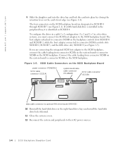
... connector SCSIA on the SCSI backplane. www.dell.com | support.dell.com 9 Slide the daughter card into the drive bay and lock the card into place by closing the retention lever on the SCSI Backplane Board power connector (POWER2) SCSI cable connector (SCSIA) system-board data cable connector (PLANAR) SCSI cable connector (SCSIB) data cable connector to optional fifth drive board (DRIVE5) 10 Reinstall the hard-disk drives in the right-hand drive bays and install the hard-disk drive lock if desired. 11 Close the system covers...
... connector SCSIA on the SCSI backplane. www.dell.com | support.dell.com 9 Slide the daughter card into the drive bay and lock the card into place by closing the retention lever on the SCSI Backplane Board power connector (POWER2) SCSI cable connector (SCSIA) system-board data cable connector (PLANAR) SCSI cable connector (SCSIB) data cable connector to optional fifth drive board (DRIVE5) 10 Reinstall the hard-disk drives in the right-hand drive bays and install the hard-disk drive lock if desired. 11 Close the system covers...

Activating the Dell PERC 3/Di
Page 3
... Figure 1-1 for the location of the socket on the hard-disk drives before changing the mode of operation of the integrated SCSI controller from its electrical outlet. Your upgrade kit includes a RAID controller memory module, RAID hardware key, RAID battery, and RAID software. Activating the Integrated RAID Controller This document explains how to activate your system Installation and Troubleshooting Guide. 2 Open the ejectors on the RAID controller memory module socket by pressing down and outward, which allows you must turn off the system and...
... Figure 1-1 for the location of the socket on the hard-disk drives before changing the mode of operation of the integrated SCSI controller from its electrical outlet. Your upgrade kit includes a RAID controller memory module, RAID hardware key, RAID battery, and RAID software. Activating the Integrated RAID Controller This document explains how to activate your system Installation and Troubleshooting Guide. 2 Open the ejectors on the RAID controller memory module socket by pressing down and outward, which allows you must turn off the system and...

Activating the Dell PERC 3/Di
Page 5
Activating the Dell PERC 3/Di 1-3 3 Align the memory module's edge connector with the latches on the system board (see Figure 1-1) and secure the key with the slot in only one way. Installing a Memory Module memory module socket ejectors (2) alignment keys (2) 5 Examine the RAID hardware key (see Figure 1-3) to ensure that allow you to install the memory module in the socket in the center of the socket (see Figure 1-2). The memory module socket has...
Activating the Dell PERC 3/Di 1-3 3 Align the memory module's edge connector with the latches on the system board (see Figure 1-1) and secure the key with the slot in only one way. Installing a Memory Module memory module socket ejectors (2) alignment keys (2) 5 Examine the RAID hardware key (see Figure 1-3) to ensure that allow you to install the memory module in the socket in the center of the socket (see Figure 1-2). The memory module socket has...

Activating the Dell PERC 3/Di
Page 7
... information, see the RAID controller documentation. Activating the Dell PERC 3/Di 1-5 See "Changing the System Setup Settings." 11 Install the RAID software. Changing the System Setup Settings 1 Turn on the hard-disk drives before changing the mode of operation of the RAID hardware. Ensure that the setting for System Setup If you wait too long and your operating system begins to load into memory, allow the system to RAID. 8 Connect the battery cable to the RAID battery connector on the system board (see Figure...
... information, see the RAID controller documentation. Activating the Dell PERC 3/Di 1-5 See "Changing the System Setup Settings." 11 Install the RAID software. Changing the System Setup Settings 1 Turn on the hard-disk drives before changing the mode of operation of the RAID hardware. Ensure that the setting for System Setup If you wait too long and your operating system begins to load into memory, allow the system to RAID. 8 Connect the battery cable to the RAID battery connector on the system board (see Figure...

Activating the Dell PERC 3/Di
Page 8
For more information, see the PERC 3/Di controller documentation. 1-6 Activating the Dell PERC 3/Di or right-arrow key to change the RAID option to save settings, and then reboot the system. 6 Configure the RAID subsystem and install the RAID driver and management software. Channel A displays RAID, and Channel B displays SCSI. (When the RAID option is set to SCSI, Channel A and Channel B display SCSI.) 5 Press to RAID Enabled. www.dell.com | support.dell.com 4 Press the left-
For more information, see the PERC 3/Di controller documentation. 1-6 Activating the Dell PERC 3/Di or right-arrow key to change the RAID option to save settings, and then reboot the system. 6 Configure the RAID subsystem and install the RAID driver and management software. Channel A displays RAID, and Channel B displays SCSI. (When the RAID option is set to SCSI, Channel A and Channel B display SCSI.) 5 Press to RAID Enabled. www.dell.com | support.dell.com 4 Press the left-
Rack Installation Guide
Page 3
... a single rack or front stabilizers for specific warning and/or caution statements and procedures. If you install the kit in other brand of two people to various peripherals or supporting hardware. Install front and side stabilizers on the rack. Thus, "component" refers to tip over and injure someone. For complete safety, regulatory, and warranty information, see the rack installation documentation accompanying the...
... a single rack or front stabilizers for specific warning and/or caution statements and procedures. If you install the kit in other brand of two people to various peripherals or supporting hardware. Install front and side stabilizers on the rack. Thus, "component" refers to tip over and injure someone. For complete safety, regulatory, and warranty information, see the rack installation documentation accompanying the...

Rack Installation Guide
Page 4
... a rack; www.dell.com | support.dell.com • Always load the rack from the rack. • Use caution when pressing the component rail release latches and sliding a component into the rack. • Do not overload the AC supply branch circuit that provides power to components in the rack. • Do not step on or stand on any system or component when servicing other...
... a rack; www.dell.com | support.dell.com • Always load the rack from the rack. • Use caution when pressing the component rail release latches and sliding a component into the rack. • Do not overload the AC supply branch circuit that provides power to components in the rack. • Do not step on or stand on any system or component when servicing other...
Rack Installation Guide
Page 6
... for Flush-Mount Configuration 1-17 Installing the System in the Rack (Flush-Mount Configuration 1-18 Securing the System in the Rack (Flush-Mount Configuration 1-19 Installing the Cable Management Arm . . . 1-20 Attaching the Strain Relief Bracket . . . . 1-21 Four-Post RapidRails Rack Kit Contents . . 1-23 One Rack Unit 1-24 Using the Template to Mark Vertical Rails 1-25 Installing the Slide Assemblies 1-27 Installing the System in the Rack . . . . . 1-29 Installing the Cable Management Arm . . . 1-30...
... for Flush-Mount Configuration 1-17 Installing the System in the Rack (Flush-Mount Configuration 1-18 Securing the System in the Rack (Flush-Mount Configuration 1-19 Installing the Cable Management Arm . . . 1-20 Attaching the Strain Relief Bracket . . . . 1-21 Four-Post RapidRails Rack Kit Contents . . 1-23 One Rack Unit 1-24 Using the Template to Mark Vertical Rails 1-25 Installing the Slide Assemblies 1-27 Installing the System in the Rack . . . . . 1-29 Installing the Cable Management Arm . . . 1-30...

Rack Installation Guide
Page 7
... "Safety Instructions" at the front of two-post rack kits: a two-post support tray kit and a two-post RapidRails™ rack kit. Rack Installation Guide 1-1 Use only the rack kit for precautionary warnings before attempting this installation. Two-Post Installation There are accommodated. Two-Post Support Tray Kit The two-post support tray kit is required for each kit in the rack. See the rack manufacturer's installation documentation for your Dell system. Both 3-inch and 6-inch wide two-post racks are two types of this kit in...
... "Safety Instructions" at the front of two-post rack kits: a two-post support tray kit and a two-post RapidRails™ rack kit. Rack Installation Guide 1-1 Use only the rack kit for precautionary warnings before attempting this installation. Two-Post Installation There are accommodated. Two-Post Support Tray Kit The two-post support tray kit is required for each kit in the rack. See the rack manufacturer's installation documentation for your Dell system. Both 3-inch and 6-inch wide two-post racks are two types of this kit in...
Rack Installation Guide
Page 25
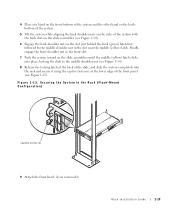
...in the slot near the middle (yellow) latch. Rack Installation Guide 1-19 4...slot just behind the back (green) latch first, followed by the middle shoulder nut in the Rack (Flush-Mount Configuration) captive screw (2) 9 Attach the front bezel, if you removed it using... the captive fasteners at the back of the slide, and slide the system completely into place, locking the slide to the middle shoulder nut (see Figure 1-14). 8 Release the locking latch at the lower edge of the front panel...
...in the slot near the middle (yellow) latch. Rack Installation Guide 1-19 4...slot just behind the back (green) latch first, followed by the middle shoulder nut in the Rack (Flush-Mount Configuration) captive screw (2) 9 Attach the front bezel, if you removed it using... the captive fasteners at the back of the slide, and slide the system completely into place, locking the slide to the middle shoulder nut (see Figure 1-14). 8 Release the locking latch at the lower edge of the front panel...

Rack Installation Guide
Page 28
... out to verify that secure the front of the RapidRails kit in most industry-standard rack cabinets. One four-post RapidRails kit is required for trained service providers to the fully extended position. www.dell.com | support.dell.com 7 Connect the remaining cables to be installed in the rack. Four-Post RapidRails Rack Kit This procedure provides instructions for each system to the system. b Slide the system...
... out to verify that secure the front of the RapidRails kit in most industry-standard rack cabinets. One four-post RapidRails kit is required for trained service providers to the fully extended position. www.dell.com | support.dell.com 7 Connect the remaining cables to be installed in the rack. Four-Post RapidRails Rack Kit This procedure provides instructions for each system to the system. b Slide the system...


