
User Manual
Page 5
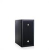
Contents Safety Instructions 5 SAFETY: Rack Mounting of Systems 5 Rack Installation Instructions 5 Rack Specifications 6 Before You Begin 6 Installation Tasks 7 Recommended Tools and Supplies 7 Removing and Replacing the Rack Doors 8 Removing and Replacing the Side Panels . . . . . 12 Reversing the Front Door (Optional 16 Securing the Rack Leveling Feet 23 Installing the Rack Stabilizer Feet 24 Adjusting the Rack Posts (Optional 27 Routing Cables 28 Coupling Two Racks 32 Contents 3
Contents Safety Instructions 5 SAFETY: Rack Mounting of Systems 5 Rack Installation Instructions 5 Rack Specifications 6 Before You Begin 6 Installation Tasks 7 Recommended Tools and Supplies 7 Removing and Replacing the Rack Doors 8 Removing and Replacing the Side Panels . . . . . 12 Reversing the Front Door (Optional 16 Securing the Rack Leveling Feet 23 Installing the Rack Stabilizer Feet 24 Adjusting the Rack Posts (Optional 27 Routing Cables 28 Coupling Two Racks 32 Contents 3
User Manual
Page 7
... circuit that shipped with any system as well as a separate document. Dell disclaims all liability and warranties with respect to the rack. • Do not stand or step on any other rack. • Before installing your equipment in the rack. The rack can allow the rack to tip over. • Always load from potential damage. CAUTION...
... circuit that shipped with any system as well as a separate document. Dell disclaims all liability and warranties with respect to the rack. • Do not stand or step on any other rack. • Before installing your equipment in the rack. The rack can allow the rack to tip over. • Always load from potential damage. CAUTION...

User Manual
Page 8
...tip over rough surfaces. If you begin installing your system in this document to others who may occur. Rack Specifications CAUTION: The rack meets the specifications of the procedures for support and to install the next system. WARNING: You must strictly...protect yourself as well as the safety instructions that came with components installed. Important Safety Information Observe the safety precautions in a rack, complete all of American National Standards Institute (ANSI), Consumer Electronics Association (CEA) Standard EIA/CEA-310-E, International Electrotechnical Commission...
...tip over rough surfaces. If you begin installing your system in this document to others who may occur. Rack Specifications CAUTION: The rack meets the specifications of the procedures for support and to install the next system. WARNING: You must strictly...protect yourself as well as the safety instructions that came with components installed. Important Safety Information Observe the safety precautions in a rack, complete all of American National Standards Institute (ANSI), Consumer Electronics Association (CEA) Standard EIA/CEA-310-E, International Electrotechnical Commission...

User Manual
Page 9
... 12-mm wrench Installation Guide 7 WARNING: After installing systems in a rack, never pull more than one system out of the rack on racks joined to other component is pulled out of the rack with the slide assemblies fully extended. Failure to install stabilizers accordingly before ...installing components in the rack. The stabilizer feet help prevent the rack from tipping over when a system or other racks. Rack Stabilizer Feet WARNING: Before installing systems in a rack, install front and side stabilizers on stand-alone racks or the front stabilizer on its ...
... 12-mm wrench Installation Guide 7 WARNING: After installing systems in a rack, never pull more than one system out of the rack on racks joined to other component is pulled out of the rack with the slide assemblies fully extended. Failure to install stabilizers accordingly before ...installing components in the rack. The stabilizer feet help prevent the rack from tipping over when a system or other racks. Rack Stabilizer Feet WARNING: Before installing systems in a rack, install front and side stabilizers on stand-alone racks or the front stabilizer on its ...

User Manual
Page 10
The hinge pin's retention clip prevents the hinge from pallet) Removing and Replacing the Rack Doors WARNING: Because of the size and weight of the hinge body. 8 Installation Guide WARNING: When storing the doors, lay the doors flat so they ..., pull the hinge pin upward so that the front door opens) • Keys to the rack doors and side panels • 13-mm wrench (for rack removal from pallet) • 17-mm wrench (for rack removal from being pulled out of the rack cabinet doors, never attempt to remove or install them by yourself.
The hinge pin's retention clip prevents the hinge from pallet) Removing and Replacing the Rack Doors WARNING: Because of the size and weight of the hinge body. 8 Installation Guide WARNING: When storing the doors, lay the doors flat so they ..., pull the hinge pin upward so that the front door opens) • Keys to the rack doors and side panels • 13-mm wrench (for rack removal from pallet) • 17-mm wrench (for rack removal from being pulled out of the rack cabinet doors, never attempt to remove or install them by yourself.

User Manual
Page 11
... bottom hinge post. Installation Guide 9 WARNING: Due to the size and weight of the door's hinge-pin housing, pull the door slightly away from the rack so that the door clears the hinge body. 4 Release the hinge pin. 5 Lift the door upward so that you lay the removed door flat with...
... bottom hinge post. Installation Guide 9 WARNING: Due to the size and weight of the door's hinge-pin housing, pull the door slightly away from the rack so that the door clears the hinge body. 4 Release the hinge pin. 5 Lift the door upward so that you lay the removed door flat with...

User Manual
Page 12
Opening and Removing the Back Doors WARNING: Because of the size and weight of the rack cabinet doors, never attempt to remove or install them by yourself. 1 Turn the door handle and open the back doors (see Figure 1-2). Opening the Back Doors 1 1 door handle 2 2 back door (2) 10 Installation Guide Replacing the Front Door To replace the front door, perform the steps for removal in reverse. Figure 1-2.
Opening and Removing the Back Doors WARNING: Because of the size and weight of the rack cabinet doors, never attempt to remove or install them by yourself. 1 Turn the door handle and open the back doors (see Figure 1-2). Opening the Back Doors 1 1 door handle 2 2 back door (2) 10 Installation Guide Replacing the Front Door To replace the front door, perform the steps for removal in reverse. Figure 1-2.

User Manual
Page 13
... with its outer surface facing upward. Figure 1-3. Removing the Back Doors 1 2 3 1 hinge pin 3 hinge-pin housing 2 hinge body WARNING: Due to prevent them from the rack. a While supporting the door, pull the pin for the bottom hinge. 2 Remove the right back door.
... with its outer surface facing upward. Figure 1-3. Removing the Back Doors 1 2 3 1 hinge pin 3 hinge-pin housing 2 hinge body WARNING: Due to prevent them from the rack. a While supporting the door, pull the pin for the bottom hinge. 2 Remove the right back door.

User Manual
Page 14
... flat with the outer surface facing upward helps prevent damage to its cosmetic coating. NOTE: You must remove the lower side panels in a rack, having the sides open makes it easier to install slide assemblies and support rails and to reverse the direction that the front door opens....side stabilizer feet. e Repeat step a through step 4 for the left back door. Removing and Replacing the Side Panels CAUTION: For stand-alone racks, reinstalling the side panels is not mandatory for removal in a safe location with the panel's outer surface facing upward to help prevent damage to its...
... flat with the outer surface facing upward helps prevent damage to its cosmetic coating. NOTE: You must remove the lower side panels in a rack, having the sides open makes it easier to install slide assemblies and support rails and to reverse the direction that the front door opens....side stabilizer feet. e Repeat step a through step 4 for the left back door. Removing and Replacing the Side Panels CAUTION: For stand-alone racks, reinstalling the side panels is not mandatory for removal in a safe location with the panel's outer surface facing upward to help prevent damage to its...

User Manual
Page 15
Figure 1-4. Replacing the Upper Side Panels 1 2 3 1 panel lip 3 latches (2) 2 upper side panel (2) Removing the Lower Side Panels 1 Pull both latches down and allow the side panel to swing outward slightly at the top. 2 Firmly grasp both sides of the panel. 3 Lift the panel upward until the panel hooks clear the holes in the bottom of the rack frame. 4 Place the panel in a safe location with the panel's outer surface facing upward to help prevent damage to its cosmetic coating. 5 Repeat step 1 through step 4 for the other lower side panel. Installation Guide 13
Figure 1-4. Replacing the Upper Side Panels 1 2 3 1 panel lip 3 latches (2) 2 upper side panel (2) Removing the Lower Side Panels 1 Pull both latches down and allow the side panel to swing outward slightly at the top. 2 Firmly grasp both sides of the panel. 3 Lift the panel upward until the panel hooks clear the holes in the bottom of the rack frame. 4 Place the panel in a safe location with the panel's outer surface facing upward to help prevent damage to its cosmetic coating. 5 Repeat step 1 through step 4 for the other lower side panel. Installation Guide 13

User Manual
Page 16
Replacing the Lower Side Panels 1 2 3 1 panel hook (2) 3 lower side panel (2) 2 latch (2) NOTE: The following procedures apply to extra-deep racks only. 14 Installation Guide Figure 1-5. Replacing the Lower Side Panels 1 Lower the panel into the rack, inserting the back panel hook into the back hole in the bottom of the rack frame and the front hook into the corresponding hole in the front of the rack frame (see Figure 1-5). 2 Swing the top end of the panel towards the rack. 3 Press the panel into the rack until both latches lock into place.
Replacing the Lower Side Panels 1 2 3 1 panel hook (2) 3 lower side panel (2) 2 latch (2) NOTE: The following procedures apply to extra-deep racks only. 14 Installation Guide Figure 1-5. Replacing the Lower Side Panels 1 Lower the panel into the rack, inserting the back panel hook into the back hole in the bottom of the rack frame and the front hook into the corresponding hole in the front of the rack frame (see Figure 1-5). 2 Swing the top end of the panel towards the rack. 3 Press the panel into the rack until both latches lock into place.

User Manual
Page 17
Replacing the Rear Side Panels 1 2 3 1 rear side panel 3 alignment bracket 4 2 screw (2) 4 slot in place from inside the rack. 2 Lift the rear side panel up and away from the rack. Removing the Rear Side Panel 1 Remove the screws (2) holding the rear side panel in PDU tray Installation Guide 15 Figure 1-6. Replacing the Rear Side Panel 1 Insert the alignment bracket located in the middle of the rear panel into the slot on the rack PDU tray. 2 Install screws at the top and bottom to secure the rear side panel.
Replacing the Rear Side Panels 1 2 3 1 rear side panel 3 alignment bracket 4 2 screw (2) 4 slot in place from inside the rack. 2 Lift the rear side panel up and away from the rack. Removing the Rear Side Panel 1 Remove the screws (2) holding the rear side panel in PDU tray Installation Guide 15 Figure 1-6. Replacing the Rear Side Panel 1 Insert the alignment bracket located in the middle of the rear panel into the slot on the rack PDU tray. 2 Install screws at the top and bottom to secure the rear side panel.

User Manual
Page 18
... the hinge body. 16 Installation Guide Reversing the Front Door (Optional) NOTE: Use a 4-mm Allen wrench to remove the front-door hinge bodies from the rack and reinstall them on page 12). 3 Reverse the top hinge body. You might need a stepladder in order to the... rack. a Pull the hinge pin slightly upward so that secures the top hinge body to access the Allen bolt that you can access the retention clip (...
... the hinge body. 16 Installation Guide Reversing the Front Door (Optional) NOTE: Use a 4-mm Allen wrench to remove the front-door hinge bodies from the rack and reinstall them on page 12). 3 Reverse the top hinge body. You might need a stepladder in order to the... rack. a Pull the hinge pin slightly upward so that secures the top hinge body to access the Allen bolt that you can access the retention clip (...

User Manual
Page 19
f Rotate the hinge body 180 degrees so that secure the hinge body to the rack, and place the bolts with the hinge pin, retention clip, and body spring. Removing the Front-Door Hinges 1 6 2 5 4 3 1 hinge pin 3 bottom hinge 5 retention clip 2 top hinge 4 hinge post 6 body spring c Remove the hinge spring from the hinge body. d Place the hinge pin, retention clip, and spring in a safe location. e Using the 4-mm Allen wrench, remove the Allen bolts that the hinge-pin holes are now on the right side of the hinge body (see Figure 1-8). Installation Guide 17 Figure 1-7.
f Rotate the hinge body 180 degrees so that secure the hinge body to the rack, and place the bolts with the hinge pin, retention clip, and body spring. Removing the Front-Door Hinges 1 6 2 5 4 3 1 hinge pin 3 bottom hinge 5 retention clip 2 top hinge 4 hinge post 6 body spring c Remove the hinge spring from the hinge body. d Place the hinge pin, retention clip, and spring in a safe location. e Using the 4-mm Allen wrench, remove the Allen bolts that the hinge-pin holes are now on the right side of the hinge body (see Figure 1-8). Installation Guide 17 Figure 1-7.

User Manual
Page 20
Figure 1-8. Reversing the Top and Bottom Hinges 1 2 3 4 5 7 6 1 hinge pin 3 spring 5 hinge post 7 front of the rack with the Allen bolts. h Insert the spring between the top and bottom hinge-pin holes in the right side of the rack, and fasten the hinge body to the right side of rack 2 top hinge body 4 retention clip 6 bottom hinge body g Locate the top bolt holes in the bottom hinge body. 18 Installation Guide
Figure 1-8. Reversing the Top and Bottom Hinges 1 2 3 4 5 7 6 1 hinge pin 3 spring 5 hinge post 7 front of the rack with the Allen bolts. h Insert the spring between the top and bottom hinge-pin holes in the right side of the rack, and fasten the hinge body to the right side of rack 2 top hinge body 4 retention clip 6 bottom hinge body g Locate the top bolt holes in the bottom hinge body. 18 Installation Guide

User Manual
Page 21
... 19 a Remove the Allen bolts that secure the hinge body to the rack, and place the bolts in the right side of the rack, and use the Allen bolts to fasten the hinge body to the right side of the rack. 5 Rotate the front door 180 degrees so that its hinge-pin housings...
... 19 a Remove the Allen bolts that secure the hinge body to the rack, and place the bolts in the right side of the rack, and use the Allen bolts to fasten the hinge body to the right side of the rack. 5 Rotate the front door 180 degrees so that its hinge-pin housings...

User Manual
Page 22
a Unscrew the two Phillips screws that hold the lock catch to the vertical frame member. c Reinstall the lock catch on page 8. 7 Reverse the lock catch. b Remove the lock catch and rotate it 180 degrees. See Figure 1-10. 20 Installation Guide 6 Replace the front door by reversing the steps in "Removing the Front Door" on the other rack front vertical frame member by aligning the holes of the catch with the holes of the frame member and then reinserting the two Phillips screws.
a Unscrew the two Phillips screws that hold the lock catch to the vertical frame member. c Reinstall the lock catch on page 8. 7 Reverse the lock catch. b Remove the lock catch and rotate it 180 degrees. See Figure 1-10. 20 Installation Guide 6 Replace the front door by reversing the steps in "Removing the Front Door" on the other rack front vertical frame member by aligning the holes of the catch with the holes of the frame member and then reinserting the two Phillips screws.

User Manual
Page 25
... clockwise with a 12-mm wrench (see Figure 1-12). 3 Repeat steps 1 and 2 for the remaining leveling feet. 4 Ensure that each corner of the rack. f Locate the sixth horizontal bar from tipping over. 1 Using a screwdriver, lower the leveling foot until it , aligning the center tabs on the badge with... location that the casters on each leveling foot is supporting the weight of clearance between the floor and the casters as you install your rack is situated on a slightly uneven floor surface. WARNING: Adjust the leveling feet until they are designed to the leveling feet. Having the...
... clockwise with a 12-mm wrench (see Figure 1-12). 3 Repeat steps 1 and 2 for the remaining leveling feet. 4 Ensure that each corner of the rack. f Locate the sixth horizontal bar from tipping over. 1 Using a screwdriver, lower the leveling foot until it , aligning the center tabs on the badge with... location that the casters on each leveling foot is supporting the weight of clearance between the floor and the casters as you install your rack is situated on a slightly uneven floor surface. WARNING: Adjust the leveling feet until they are designed to the leveling feet. Having the...

User Manual
Page 26
... a suite. 24 Installation Guide Adjusting the Leveling Feet 1 2 3 1 leveling foot stem 3 leveling pad 2 hex nut Installing the Rack Stabilizer Feet WARNING: Installing systems in a rack without the front and side stabilizer feet installed could cause the rack to tip over, potentially resulting in a suite, and install left or right stabilizer feet on all...
... a suite. 24 Installation Guide Adjusting the Leveling Feet 1 2 3 1 leveling foot stem 3 leveling pad 2 hex nut Installing the Rack Stabilizer Feet WARNING: Installing systems in a rack without the front and side stabilizer feet installed could cause the rack to tip over, potentially resulting in a suite, and install left or right stabilizer feet on all...

User Manual
Page 27
Figure 1-13. Installing the Front Stabilizer Feet 1 1 front stabilizer foot (2) Installation Guide 25 Installing the Front Stabilizer Feet 1 Open the front door. 2 Reach into the rack and pull up firmly on each stabilizer to detach them from the frame. 3 Remove the plastic fasteners attached to the stabilizer feet. 4 Position each front stabilizer foot against the base of the rack frame and align its holes with the corresponding holes in the frame. 5 Use the provided bolts, washers, and cage nuts to secure each foot to the rack as shown in Figure 1-13.
Figure 1-13. Installing the Front Stabilizer Feet 1 1 front stabilizer foot (2) Installation Guide 25 Installing the Front Stabilizer Feet 1 Open the front door. 2 Reach into the rack and pull up firmly on each stabilizer to detach them from the frame. 3 Remove the plastic fasteners attached to the stabilizer feet. 4 Position each front stabilizer foot against the base of the rack frame and align its holes with the corresponding holes in the frame. 5 Use the provided bolts, washers, and cage nuts to secure each foot to the rack as shown in Figure 1-13.


