
User Manual
Page 5
Contents Safety Instructions 5 SAFETY: Rack Mounting of Systems 5 Rack Installation Instructions 5 Rack Specifications 6 Before You Begin 6 Installation Tasks 7 Recommended Tools and Supplies 7 Removing and Replacing the Rack Doors 8 Removing and Replacing the Side Panels . . . . . 12 Reversing the Front Door (Optional 16 Securing the Rack Leveling Feet 23 Installing the Rack Stabilizer Feet 24 Adjusting the Rack Posts (Optional 27 Routing Cables 28 Coupling Two Racks 32 Contents 3
Contents Safety Instructions 5 SAFETY: Rack Mounting of Systems 5 Rack Installation Instructions 5 Rack Specifications 6 Before You Begin 6 Installation Tasks 7 Recommended Tools and Supplies 7 Removing and Replacing the Rack Doors 8 Removing and Replacing the Side Panels . . . . . 12 Reversing the Front Door (Optional 16 Securing the Rack Leveling Feet 23 Installing the Rack Stabilizer Feet 24 Adjusting the Rack Posts (Optional 27 Routing Cables 28 Coupling Two Racks 32 Contents 3

User Manual
Page 26
..., always install the stabilizer feet before installing components in a suite, and install left or right stabilizer feet on the racks at each end of a suite. 24 Installation Guide Figure 1-12. Adjusting the Leveling Feet 1 2 3 1 leveling foot stem 3 leveling pad 2 hex nut Installing the Rack Stabilizer Feet WARNING: Installing systems in a rack...
..., always install the stabilizer feet before installing components in a suite, and install left or right stabilizer feet on the racks at each end of a suite. 24 Installation Guide Figure 1-12. Adjusting the Leveling Feet 1 2 3 1 leveling foot stem 3 leveling pad 2 hex nut Installing the Rack Stabilizer Feet WARNING: Installing systems in a rack...

User Manual
Page 36
b Adjust the leveling feet on the racks, hook the brackets into the square holes inside and adjacent to the rack posts, and tighten the brackets using the wingnuts (see "Adjusting the Leveling Feet" on page 24. Coupling Two Racks 1 3 2 1 coupling bracket locations 3 coupling bracket (4) 2 wingnut 34 Installation Guide a Position the two racks side by side. c To install the coupling brackets on both racks so that the racks are parallel and in the same horizontal plane. Figure 1-21. For instructions, see Figure 1-21). 5 Install the coupling brackets.
b Adjust the leveling feet on the racks, hook the brackets into the square holes inside and adjacent to the rack posts, and tighten the brackets using the wingnuts (see "Adjusting the Leveling Feet" on page 24. Coupling Two Racks 1 3 2 1 coupling bracket locations 3 coupling bracket (4) 2 wingnut 34 Installation Guide a Position the two racks side by side. c To install the coupling brackets on both racks so that the racks are parallel and in the same horizontal plane. Figure 1-21. For instructions, see Figure 1-21). 5 Install the coupling brackets.
Dell PowerEdge 2420 Rack Installation Guide
Page 7
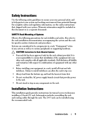
...rack cabinet provided. Installation Guide 5 "Component" refers to combinations of equipment with any system as well as a separate document. Dell disclaims all applicable standards. SAFETY: Rack Mounting of the equipment into any components in a rack. CAUTION: Instructions for Rack-Mounted... Systems: • Your rack kit has been approved only for trained service technicians installing a 24-unit (U) rack. For complete safety and regulatory information, see the safety instructions that installation of Systems Observe the following safety...
...rack cabinet provided. Installation Guide 5 "Component" refers to combinations of equipment with any system as well as a separate document. Dell disclaims all applicable standards. SAFETY: Rack Mounting of the equipment into any components in a rack. CAUTION: Instructions for Rack-Mounted... Systems: • Your rack kit has been approved only for trained service technicians installing a 24-unit (U) rack. For complete safety and regulatory information, see the safety instructions that installation of Systems Observe the following safety...

Dell PowerEdge 2420 Rack Installation Guide
Page 8
... the safety precautions in the following subsections when installing your rack, carefully read through this document to install the next system. Rack Requirements CAUTION: The 24-U rack meets the specifications of cabinet control may become unstable and tip over rough surfaces. Avoid long or steep inclines, rough surfaces, or ramps where...
... the safety precautions in the following subsections when installing your rack, carefully read through this document to install the next system. Rack Requirements CAUTION: The 24-U rack meets the specifications of cabinet control may become unstable and tip over rough surfaces. Avoid long or steep inclines, rough surfaces, or ramps where...

Dell PowerEdge 2420 Rack Installation Guide
Page 25
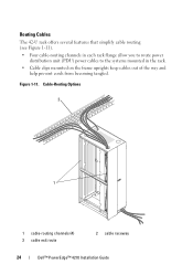
Routing Cables The 24-U rack offers several features that simplify cable routing (see Figure 1-14). Installation Guide 23 You can route cables out of the rack in two ways ...
Routing Cables The 24-U rack offers several features that simplify cable routing (see Figure 1-14). Installation Guide 23 You can route cables out of the rack in two ways ...

Dell PowerEdge 2420 Rack Installation Guide
Page 26
Figure 1-14. Cable-Routing Options 1 2 3 4 1 cable raceway 3 cable clips 5 bottom cable exit 5 2 top cable slot 4 PDU channels (2 per side) 24 Installation Guide
Figure 1-14. Cable-Routing Options 1 2 3 4 1 cable raceway 3 cable clips 5 bottom cable exit 5 2 top cable slot 4 PDU channels (2 per side) 24 Installation Guide

User Manual
Page 5
... Replacing the Side Panels 14 Reversing the Front Door (optional 14 Securing the Rack Leveling Feet 19 Installing the Rack Stabilizer Feet 21 Routing Cables 24 Removing the Door Panels From the Optional Door Kit 26 Coupling Two Racks 26 Index 31 Contents 3
... Replacing the Side Panels 14 Reversing the Front Door (optional 14 Securing the Rack Leveling Feet 19 Installing the Rack Stabilizer Feet 21 Routing Cables 24 Removing the Door Panels From the Optional Door Kit 26 Coupling Two Racks 26 Index 31 Contents 3
User Manual
Page 26
Cable-Routing Options 2 1 1 cable-routing channels (4) 3 cable exit route 2 cable raceway 24 Dell™ PowerEdge™ 4210 Installation Guide Figure 1-11. Routing Cables The 42-U rack offers several features that simplify cable routing (see Figure 1-11). • Four cable-routing channels in each rack flange allow you to route power distribution unit (PDU) power cables to the systems mounted in the rack. • Cable clips mounted on the frame uprights keep cables out of the way and help prevent cords from becoming tangled.
Cable-Routing Options 2 1 1 cable-routing channels (4) 3 cable exit route 2 cable raceway 24 Dell™ PowerEdge™ 4210 Installation Guide Figure 1-11. Routing Cables The 42-U rack offers several features that simplify cable routing (see Figure 1-11). • Four cable-routing channels in each rack flange allow you to route power distribution unit (PDU) power cables to the systems mounted in the rack. • Cable clips mounted on the frame uprights keep cables out of the way and help prevent cords from becoming tangled.

User Manual
Page 33
Index B back door opening, 10 removing, 11 C cables routing, 24 coupling two racks, 26 D doors removing, 8 F front door removing, 8, 10 L leveling feet, 19 R rack mount precautions, 7 rack stabilizer feet, 7, 21 routing cables, 24 S safety instructions, 5 side panels removing, 13-14 stabilizer feet installing front-stabilizer foot, 21 installing side-stabilizer foot, 22 T tools and supplies, 8 Index 31
Index B back door opening, 10 removing, 11 C cables routing, 24 coupling two racks, 26 D doors removing, 8 F front door removing, 8, 10 L leveling feet, 19 R rack mount precautions, 7 rack stabilizer feet, 7, 21 routing cables, 24 S safety instructions, 5 side panels removing, 13-14 stabilizer feet installing front-stabilizer foot, 21 installing side-stabilizer foot, 22 T tools and supplies, 8 Index 31

