Activating the Dell PERC2
Page 3
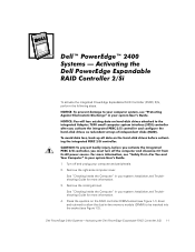
Remove the cooling shroud. Dell PowerEdge 2400 Systems-Activating the Dell PowerEdge Expandable RAID Controller 2/Si 1-1 See "Checking Inside the Computer" in your system Installation and Troubleshooting Guide for more information. 4. See "Checking Inside the Computer" in your computer and peripherals. 2. To activate the integrated PowerEdge Expandable RAID Controller (PERC) 2/Si, perform the following steps. 1. Turn off...
Remove the cooling shroud. Dell PowerEdge 2400 Systems-Activating the Dell PowerEdge Expandable RAID Controller 2/Si 1-1 See "Checking Inside the Computer" in your system Installation and Troubleshooting Guide for more information. 4. See "Checking Inside the Computer" in your computer and peripherals. 2. To activate the integrated PowerEdge Expandable RAID Controller (PERC) 2/Si, perform the following steps. 1. Turn off...
Activating the Dell PERC2
Page 4
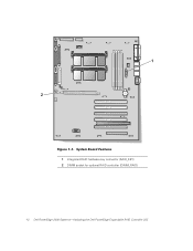
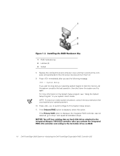
1 Integrated RAID hardware key connector (RAID_KEY) 2 DIMM socket for optional RAID controller (DIMM_RAID) 1-2 Dell PowerEdge 2400 Systems-Activating the Dell PowerEdge Expandable RAID Controller 2/Si
1 Integrated RAID hardware key connector (RAID_KEY) 2 DIMM socket for optional RAID controller (DIMM_RAID) 1-2 Dell PowerEdge 2400 Systems-Activating the Dell PowerEdge Expandable RAID Controller 2/Si
Activating the Dell PERC2
Page 5
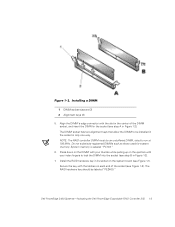
Do not substitute registered DIMMs such as those used for system memory. System memory is labeled "PC133." 6. Dell PowerEdge 2400 Systems-Activating the Dell PowerEdge Expandable RAID Controller 2/Si 1-3 Press down on the DIMM with your thumbs while pulling up on the ejectors with your index fingers to lock the ...
Do not substitute registered DIMMs such as those used for system memory. System memory is labeled "PC133." 6. Dell PowerEdge 2400 Systems-Activating the Dell PowerEdge Expandable RAID Controller 2/Si 1-3 Press down on the DIMM with your thumbs while pulling up on the ejectors with your index fingers to lock the ...
Activating the Dell PERC2
Page 6
... too long and your operating system. 10. then shut down the system and try again. Press to switch to step 1 and repeat all installation steps. 1-4 Dell PowerEdge 2400 Systems-Activating the Dell PowerEdge Expandable RAID Controller 2/Si 1 RAID hardware key 2 Latches (2) 3 Socket 8.
... too long and your operating system. 10. then shut down the system and try again. Press to switch to step 1 and repeat all installation steps. 1-4 Dell PowerEdge 2400 Systems-Activating the Dell PowerEdge Expandable RAID Controller 2/Si 1 RAID hardware key 2 Latches (2) 3 Socket 8.
Activating the Dell PERC2
Page 7
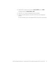
For more information, refer to RAID. The default setting for Onboard RAID is SCSI. 13. 12. Configure the RAID subsystem and install the RAID driver and management software. Dell PowerEdge 2400 Systems-Activating the Dell PowerEdge Expandable RAID Controller 2/Si 1-5 Press the left- or right-arrow key to set the Onboard RAID option to the integrated PERC 2/Si controller documentation. Press to save the settings and reboot the system. 14.
For more information, refer to RAID. The default setting for Onboard RAID is SCSI. 13. 12. Configure the RAID subsystem and install the RAID driver and management software. Dell PowerEdge 2400 Systems-Activating the Dell PowerEdge Expandable RAID Controller 2/Si 1-5 Press the left- or right-arrow key to set the Onboard RAID option to the integrated PERC 2/Si controller documentation. Press to save the settings and reboot the system. 14.

Activating the Dell PERC2
Page 8
1-6 Dell PowerEdge 2400 Systems-Activating the Dell PowerEdge Expandable RAID Controller 2/Si
1-6 Dell PowerEdge 2400 Systems-Activating the Dell PowerEdge Expandable RAID Controller 2/Si
Installing an Air Baffle on Systems With a Single 866-MHz Processor
Page 1
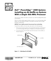
...10MRD Rev. Line up the holes on the terminator card with the posts on the air baffle, as described in your Dell PowerEdge 2400 system documentation. (Rev. 3/29/00) FILE LOCATION: D:\test\10MRDam1.fm This document updates information contained in Figure 1-1.... Remove the terminator card from the guide bracket assembly, as shown in your Dell PowerEdge 2400 Systems Installation and Troubleshooting Guide. 2. retaining tab air baffle terminator card DELL CONFIDENTIAL - To install the air baffle on the system's terminator card for singleprocessor configurations. A01...
...10MRD Rev. Line up the holes on the terminator card with the posts on the air baffle, as described in your Dell PowerEdge 2400 system documentation. (Rev. 3/29/00) FILE LOCATION: D:\test\10MRDam1.fm This document updates information contained in Figure 1-1.... Remove the terminator card from the guide bracket assembly, as shown in your Dell PowerEdge 2400 Systems Installation and Troubleshooting Guide. 2. retaining tab air baffle terminator card DELL CONFIDENTIAL - To install the air baffle on the system's terminator card for singleprocessor configurations. A01...
Installing Redundant Power Supplies
Page 3
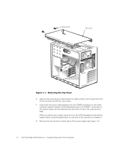
Remove the front bezel and both computer covers. Disconnect the AC power cable from the AC power receptacle on upgrading your Dell system with dual, redundant hot-plug power supplies and a power-supply distribution board (PSDB). 1. Remove the two screws at the front edge of the power supply. 3. Installing Redundant Power Supplies 1-1 For instructions, see Figure 1-1). This document provides instructions on the back of the top cover (see Chapter 7, Checking Inside the Computer, in the Installation and Troubleshooting Guide. 2. Dell PowerEdge 2400 Systems -
Remove the front bezel and both computer covers. Disconnect the AC power cable from the AC power receptacle on upgrading your Dell system with dual, redundant hot-plug power supplies and a power-supply distribution board (PSDB). 1. Remove the two screws at the front edge of the power supply. 3. Installing Redundant Power Supplies 1-1 For instructions, see Figure 1-1). This document provides instructions on the back of the top cover (see Chapter 7, Checking Inside the Computer, in the Installation and Troubleshooting Guide. 2. Dell PowerEdge 2400 Systems -
Installing Redundant Power Supplies
Page 4
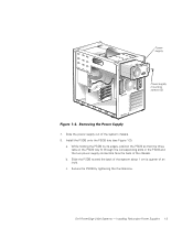
... cover 4. Installing Redundant Power Supplies Slide the top cover about 2 centimeters (cm) (about half an inch) toward the front of the power supply (see Figure 1-2). 1-2 Dell PowerEdge 2400 Systems - Remove the two screws on either side of the computer and lift the cover away. 5. Disconnect the power cable harness from the SCSI backplane...
... cover 4. Installing Redundant Power Supplies Slide the top cover about 2 centimeters (cm) (about half an inch) toward the front of the power supply (see Figure 1-2). 1-2 Dell PowerEdge 2400 Systems - Remove the two screws on either side of the computer and lift the cover away. 5. Disconnect the power cable harness from the SCSI backplane...
Installing Redundant Power Supplies
Page 5
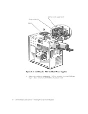
b. Dell PowerEdge 2400 Systems - Secure the PSDB by its edges, position the PSDB so that the three tabs on the PSDB tray fit through the corresponding slots in the PSDB and the two power supply connectors face the back of the system chassis. 8. Power supply Power-supply mounting screws (2) 7. Install the PSDB onto the PSDB tray (see Figure 1-3): a. Slide the power supply out of the chassis. Installing Redundant Power Supplies 1-3 While holding the PSDB by tightening the thumbscrew. Slide the PSDB toward the back of the system about 1 cm (a quarter of an inch). c.
b. Dell PowerEdge 2400 Systems - Secure the PSDB by its edges, position the PSDB so that the three tabs on the PSDB tray fit through the corresponding slots in the PSDB and the two power supply connectors face the back of the system chassis. 8. Power supply Power-supply mounting screws (2) 7. Install the PSDB onto the PSDB tray (see Figure 1-3): a. Slide the power supply out of the chassis. Installing Redundant Power Supplies 1-3 While holding the PSDB by tightening the thumbscrew. Slide the PSDB toward the back of the system about 1 cm (a quarter of an inch). c.
Installing Redundant Power Supplies
Page 6
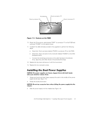
Power supplies (2) PSDB Catch on the system board. 1-4 Dell PowerEdge 2400 Systems - Attach the 12-conductor cable labeled "PWR3" to connector P3 on the PSDB (see Figure 1-4) and to connector POWER2 on power supply handle 9. Installing Redundant Power Supplies
Power supplies (2) PSDB Catch on the system board. 1-4 Dell PowerEdge 2400 Systems - Attach the 12-conductor cable labeled "PWR3" to connector P3 on the PSDB (see Figure 1-4) and to connector POWER2 on power supply handle 9. Installing Redundant Power Supplies
Installing Redundant Power Supplies
Page 7
.... Connect the remaining connectors on the PSDB. Slide the power supply into the chassis (see Figure 1-3). 2. Rotate the handle downward. 3. Replace the two computer covers. 1. Dell PowerEdge 2400 Systems - Using your thumb and index finger, squeeze the catch in the middle of the power supply handle (see Figure 1-3). Thumbscrew Power connector P2 Power...
.... Connect the remaining connectors on the PSDB. Slide the power supply into the chassis (see Figure 1-3). 2. Rotate the handle downward. 3. Replace the two computer covers. 1. Dell PowerEdge 2400 Systems - Using your thumb and index finger, squeeze the catch in the middle of the power supply handle (see Figure 1-3). Thumbscrew Power connector P2 Power...
Installing Redundant Power Supplies
Page 8
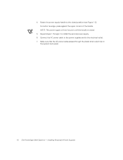
Make sure that the AC power cable passes through 4 to the electrical outlet. 7. Installing Redundant Power Supplies Repeat steps 1 through the plastic strain-relief clip on the system back panel. 1-6 Dell PowerEdge 2400 Systems - Connect the AC power cable to the power supplies and to install the second power supply. 6. Rotate the power supply handle to the closed . 5. For better leverage, press against the upper corners of the handle. 4. NOTE: The power supply will not function until the handle is closed position (see Figure 1-3).
Make sure that the AC power cable passes through 4 to the electrical outlet. 7. Installing Redundant Power Supplies Repeat steps 1 through the plastic strain-relief clip on the system back panel. 1-6 Dell PowerEdge 2400 Systems - Connect the AC power cable to the power supplies and to install the second power supply. 6. Rotate the power supply handle to the closed . 5. For better leverage, press against the upper corners of the handle. 4. NOTE: The power supply will not function until the handle is closed position (see Figure 1-3).
Rack Installation Guide
Page 13
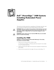
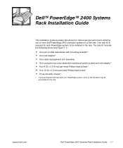
... to be preinstalled in the rack. One rack kit is required for trained service technicians installing one or more Dell PowerEdge 2400 computer systems in the rack. support.dell.com Dell PowerEdge 2400 Systems Rack Installation Guide 1-1 The rack kit includes the following items (see Figure 1-1): • One pair of slide assemblies with mounting brackets* &#...x 0.313-inch pan-head Phillips-head screws* • One 10-32 x 0.5-inch pan-head Phillips-head screw* • Three shoulder screws* * If you purchased a Dell rack with your PowerEdge system, some of the hardware may be installed in...
... to be preinstalled in the rack. One rack kit is required for trained service technicians installing one or more Dell PowerEdge 2400 computer systems in the rack. support.dell.com Dell PowerEdge 2400 Systems Rack Installation Guide 1-1 The rack kit includes the following items (see Figure 1-1): • One pair of slide assemblies with mounting brackets* &#...x 0.313-inch pan-head Phillips-head screws* • One 10-32 x 0.5-inch pan-head Phillips-head screw* • Three shoulder screws* * If you purchased a Dell rack with your PowerEdge system, some of the hardware may be installed in...
Rack Installation Guide
Page 14
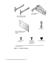
Figure 1-1. slide assemblies (1 pair) with mounting brackets* cable-management arm assembly top cover assembly including shoulder screws and rack adapter * rack adapter (1) 10-32 x 0.5-inch screws (1) 8-32 x 0.313inch screws (4) *2 screws may be installed shoulder screws (3) * If you purchased a Dell rack with your PowerEdge system, some of the hardware may be preinstalled in the rack. Rack Kit Contents 1-2 Dell PowerEdge 2400 Systems Rack Installation Guide
Figure 1-1. slide assemblies (1 pair) with mounting brackets* cable-management arm assembly top cover assembly including shoulder screws and rack adapter * rack adapter (1) 10-32 x 0.5-inch screws (1) 8-32 x 0.313inch screws (4) *2 screws may be installed shoulder screws (3) * If you purchased a Dell rack with your PowerEdge system, some of the hardware may be preinstalled in the rack. Rack Kit Contents 1-2 Dell PowerEdge 2400 Systems Rack Installation Guide
Rack Installation Guide
Page 15
... slide assemblies in the rack, perform the following steps. support.dell.com Dell PowerEdge 2400 Systems Rack Installation Guide 1-3 Open the latch on installing the PowerEdge system itself, see Figure 1-2). If you purchased a Dell rack along with your PowerEdge system in the rack, carefully read "Safety Instructions" found later... of the doors, never attempt to the doors while installing the kit. Before You Begin Before you begin installing your PowerEdge system, the slide assemblies may be preinstalled in the rack. CAUTION: To prevent personal injury due to the size and...
... slide assemblies in the rack, perform the following steps. support.dell.com Dell PowerEdge 2400 Systems Rack Installation Guide 1-3 Open the latch on installing the PowerEdge system itself, see Figure 1-2). If you purchased a Dell rack along with your PowerEdge system in the rack, carefully read "Safety Instructions" found later... of the doors, never attempt to the doors while installing the kit. Before You Begin Before you begin installing your PowerEdge system, the slide assemblies may be preinstalled in the rack. CAUTION: To prevent personal injury due to the size and...
Rack Installation Guide
Page 16
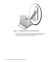
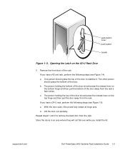
Opening the Latch on the 24-U Rack Door If you have a 42-U rack cabinet, slide the latch's push-button cover up as far as it will go, press the push button, rotate the handle clockwise until the latch releases, and then pull the door open (see Figure 1-3). 1-4 Dell PowerEdge 2400 Systems Rack Installation Guide Figure 1-2.
Opening the Latch on the 24-U Rack Door If you have a 42-U rack cabinet, slide the latch's push-button cover up as far as it will go, press the push button, rotate the handle clockwise until the latch releases, and then pull the door open (see Figure 1-3). 1-4 Dell PowerEdge 2400 Systems Rack Installation Guide Figure 1-2.
Rack Installation Guide
Page 17
Repeat steps 1 and 2 to stabilize it. support.dell.com Dell PowerEdge 2400 Systems Rack Installation Guide 1-5 If you have a 24-U rack, perform the following steps (see Figure 1-5): a. With the door open, lift out and fully retract all ...
Repeat steps 1 and 2 to stabilize it. support.dell.com Dell PowerEdge 2400 Systems Rack Installation Guide 1-5 If you have a 24-U rack, perform the following steps (see Figure 1-5): a. With the door open, lift out and fully retract all ...
Rack Installation Guide
Page 18
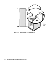
Removing the 42-U Rack Doors hinge release lever 1-6 Dell PowerEdge 2400 Systems Rack Installation Guide Figure 1-4.
Removing the 42-U Rack Doors hinge release lever 1-6 Dell PowerEdge 2400 Systems Rack Installation Guide Figure 1-4.
Rack Installation Guide
Page 19
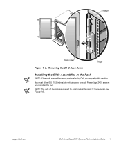
support.dell.com Dell PowerEdge 2400 Systems Rack Installation Guide 1-7 NOTE: The rails of vertical space for each PowerEdge 2400 system you may skip this section. You must allow 6 U (10.5 inches) of the rack are marked by Dell, you install in 1-U increments (see Figure 1-6). hinge pin hinge insert hinge Figure 1-5. Removing the 24-U Rack Doors Installing the Slide Assemblies in the Rack NOTE: If the slide assemblies were preinstalled by small indentations in the rack.
support.dell.com Dell PowerEdge 2400 Systems Rack Installation Guide 1-7 NOTE: The rails of vertical space for each PowerEdge 2400 system you may skip this section. You must allow 6 U (10.5 inches) of the rack are marked by Dell, you install in 1-U increments (see Figure 1-6). hinge pin hinge insert hinge Figure 1-5. Removing the 24-U Rack Doors Installing the Slide Assemblies in the Rack NOTE: If the slide assemblies were preinstalled by small indentations in the rack.


