Service Manual
Page 10
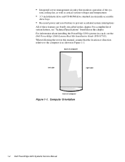
... All of computer Figure 1-1. For a complete list of the sys- Computer Orientation 1-2 Dell PowerEdge 2200 Systems Service Manual back of computer left side right side front of these features are briefly described in this manual, assume that monitors operation of system features, see the Dell PowerEdge 2200 Systems Rack Kit Installation Guide (P/N 87743). When following the text in this...
... All of computer Figure 1-1. For a complete list of the sys- Computer Orientation 1-2 Dell PowerEdge 2200 Systems Service Manual back of computer left side right side front of these features are briefly described in this manual, assume that monitors operation of system features, see the Dell PowerEdge 2200 Systems Rack Kit Installation Guide (P/N 87743). When following the text in this...

Service Manual
Page 12
system power supply control panel assembly diskette drive CD-ROM drive third drive bay diskette controller cable power cables control panel cable SCSI cable system cooling fan front bezel internal hard-disk drive cage Figure 1-3. Front/Right Side Internal View system-board/ mounting plate assembly 1-4 Dell PowerEdge 2200 Systems Service Manual
system power supply control panel assembly diskette drive CD-ROM drive third drive bay diskette controller cable power cables control panel cable SCSI cable system cooling fan front bezel internal hard-disk drive cage Figure 1-3. Front/Right Side Internal View system-board/ mounting plate assembly 1-4 Dell PowerEdge 2200 Systems Service Manual

Service Manual
Page 14
...drive in the middle externally accessible drive bay, and a SCSI drive installed in the lower externally accessible drive bay. 1-6 Dell PowerEdge 2200 Systems Service Manual The six expansion-card slots include three EISA expansion-card connectors and three PCI expansion-card connectors. Video Controller The video ...Integrated Server Management The system board contains integrated server management circuitry that can support a mixture of the Dell PowerEdge 2200 Systems User's Guide. The standard video subsystem contains 1 MB of a high-speed, high-resolution VGA-compatible video subsystem.
...drive in the middle externally accessible drive bay, and a SCSI drive installed in the lower externally accessible drive bay. 1-6 Dell PowerEdge 2200 Systems Service Manual The six expansion-card slots include three EISA expansion-card connectors and three PCI expansion-card connectors. Video Controller The video ...Integrated Server Management The system board contains integrated server management circuitry that can support a mixture of the Dell PowerEdge 2200 Systems User's Guide. The standard video subsystem contains 1 MB of a high-speed, high-resolution VGA-compatible video subsystem.
Service Manual
Page 16
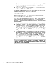
...SCSI controller card for the built-in the system, they will be corrupted during transmission. 1-8 Dell PowerEdge 2200 Systems Service Manual Figure 1-5 shows an example of the stillavailable SCSI ID numbers. • If Dell installs additional SCSI hard-disk drives in SCSI controller. NOTE: There is no action is ... jumper on the drives or data may be configured as SCSI ID 0. Therefore, regardless of the SCSI chain and disabled for the PowerEdge 2200 system. • If you install or remove a termination jumper, do not move or remove any other jumpers installed on a CD...
...SCSI controller card for the built-in the system, they will be corrupted during transmission. 1-8 Dell PowerEdge 2200 Systems Service Manual Figure 1-5 shows an example of the stillavailable SCSI ID numbers. • If Dell installs additional SCSI hard-disk drives in SCSI controller. NOTE: There is no action is ... jumper on the drives or data may be configured as SCSI ID 0. Therefore, regardless of the SCSI chain and disabled for the PowerEdge 2200 system. • If you install or remove a termination jumper, do not move or remove any other jumpers installed on a CD...
Service Manual
Page 18
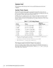
... to +5.25 VDC 50 mA 1 Maximum continuous DC output power should not exceed 170 W. 2 The total power of the connectors. 1-10 Dell PowerEdge 2200 Systems Service Manual System Unit The following subsections provide service-related information about the computer. NOTE: The power supply produces DC voltages only under its loaded condition. Maximum combined load on the...
... to +5.25 VDC 50 mA 1 Maximum continuous DC output power should not exceed 170 W. 2 The total power of the connectors. 1-10 Dell PowerEdge 2200 Systems Service Manual System Unit The following subsections provide service-related information about the computer. NOTE: The power supply produces DC voltages only under its loaded condition. Maximum combined load on the...
Service Manual
Page 20
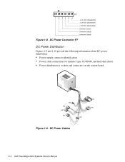
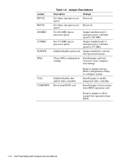
DC Power Connector P7 DC Power Distribution Figures 1-9 and 1-10 provide the following information about DC power distribution: • Power-supply connector identification • Power cable connections for diskette, tape, CD-ROM, and hard-disk drives • Power distribution to sockets and connectors on the system board P1 P4 P5 P7 P6 P3 P2 Figure 1-9. P7 1 2 34 5 6 +3.3 VDC (blue/white) +3.3 VDC (blue/white) +3.3 VDC (blue/white) common (black) common (black) common (black) Figure 1-8. DC Power Cables 1-12 Dell PowerEdge 2200 Systems Service Manual
DC Power Connector P7 DC Power Distribution Figures 1-9 and 1-10 provide the following information about DC power distribution: • Power-supply connector identification • Power cable connections for diskette, tape, CD-ROM, and hard-disk drives • Power distribution to sockets and connectors on the system board P1 P4 P5 P7 P6 P3 P2 Figure 1-9. P7 1 2 34 5 6 +3.3 VDC (blue/white) +3.3 VDC (blue/white) +3.3 VDC (blue/white) common (black) common (black) common (black) Figure 1-8. DC Power Cables 1-12 Dell PowerEdge 2200 Systems Service Manual

Service Manual
Page 22
... connector (HDLED) auxiliary fan connector (AUXFAN) configuration jumpers PCI connectors (PCI4 [bottom], PCI5, and PCI6) server management connector (SVR_MGT) 1-14 Dell PowerEdge 2200 Systems Service Manual System Board Layout The subsections that follow provide service-related information about the system board components. diskette controller connector (FLOPPY) fan connector (FAN) keyboard (bottom) and mouse (top) connectors (KYBD...
... connector (HDLED) auxiliary fan connector (AUXFAN) configuration jumpers PCI connectors (PCI4 [bottom], PCI5, and PCI6) server management connector (SVR_MGT) 1-14 Dell PowerEdge 2200 Systems Service Manual System Board Layout The subsections that follow provide service-related information about the system board components. diskette controller connector (FLOPPY) fan connector (FAN) keyboard (bottom) and mouse (top) connectors (KYBD...
Service Manual
Page 24
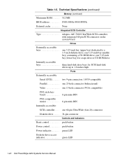
... microprocessor's internal speed is 233 MHz. Enables/disables password Jumper installed to enable integrated video controller. Remove jumper to boot system from BIOS. 1-16 Dell PowerEdge 2200 Systems Service Manual Install jumper to activate boot password feature. Jumper Descriptions Description Settings For future microprocessor Reserved. tion settings. Install jumper to allow normal boot operation from...
... microprocessor's internal speed is 233 MHz. Enables/disables password Jumper installed to enable integrated video controller. Remove jumper to boot system from BIOS. 1-16 Dell PowerEdge 2200 Systems Service Manual Install jumper to activate boot password feature. Jumper Descriptions Description Settings For future microprocessor Reserved. tion settings. Install jumper to allow normal boot operation from...
Service Manual
Page 28
... . . . . . 34-pin connector Controls and Indicators Reset control push button Power control push button Power indicator green LED Diskette-drive access indicator green LED 1-20 Dell PowerEdge 2200 Systems Service Manual one 5.25-inch bay (upper bay) dedicated to 1.6 inches high Ports Externally accessible: Serial (DTE two 9-pin connectors; 16550-compatible Parallel one 25-hole...
... . . . . . 34-pin connector Controls and Indicators Reset control push button Power control push button Power indicator green LED Diskette-drive access indicator green LED 1-20 Dell PowerEdge 2200 Systems Service Manual one 5.25-inch bay (upper bay) dedicated to 1.6 inches high Ports Externally accessible: Serial (DTE two 9-pin connectors; 16550-compatible Parallel one 25-hole...

Service Manual
Page 30
Table 1-5. square wave form: 27 G for 2 ms; Technical Specifications (continued) Environmental (continued) Maximum shock: Operating half-sine wave form: 50 G for 2 ms Storage half-sine wave form: 110 G for 15 ms Altitude: Operating 16 to 3048 m (-50 to 10,000 ft) Storage 16 to 10,600 m (-50 to 35,000 ft) z 1-22 Dell PowerEdge 2200 Systems Service Manual
Table 1-5. square wave form: 27 G for 2 ms; Technical Specifications (continued) Environmental (continued) Maximum shock: Operating half-sine wave form: 50 G for 2 ms Storage half-sine wave form: 110 G for 15 ms Altitude: Operating 16 to 3048 m (-50 to 10,000 ft) Storage 16 to 10,600 m (-50 to 35,000 ft) z 1-22 Dell PowerEdge 2200 Systems Service Manual
Service Manual
Page 32
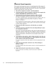
... enough to the serial and parallel port connectors are sticking. Each of the serial and parallel interface cables must be necessary to replace the keyboard. 2-2 Dell PowerEdge 2200 Systems Service Manual Verify that the keyboard and mouse interface cables are firmly attached to ensure a firm connection. 4. For proper connection of the video monitor, see "System...
... enough to the serial and parallel port connectors are sticking. Each of the serial and parallel interface cables must be necessary to replace the keyboard. 2-2 Dell PowerEdge 2200 Systems Service Manual Verify that the keyboard and mouse interface cables are firmly attached to ensure a firm connection. 4. For proper connection of the video monitor, see "System...

Service Manual
Page 34
...access indicators: These indicators light up during system operations. No. When you proceed with a metal surface on the chassis. 2-4 Dell PowerEdge 2200 Systems Service Manual • System error messages: These messages can get extremely hot during the boot routine, troubleshoot the diskette drive or hard-disk...If either of a problem, such as a loose expansion card, cable connector, or mounting screw. Observe the monitor screen for the Dell Server Assistant main menu. Remove the computer cover as appropriate. 5. Proceed to or from the drives. Be sure it has had ...
...access indicators: These indicators light up during system operations. No. When you proceed with a metal surface on the chassis. 2-4 Dell PowerEdge 2200 Systems Service Manual • System error messages: These messages can get extremely hot during the boot routine, troubleshoot the diskette drive or hard-disk...If either of a problem, such as a loose expansion card, cable connector, or mounting screw. Observe the monitor screen for the Dell Server Assistant main menu. Remove the computer cover as appropriate. 5. Proceed to or from the drives. Be sure it has had ...

Service Manual
Page 36
... a particular area or subsystem Getting Help If none of the troubleshooting procedures in this chapter or the tests in the Diagnostics and Troubleshooting Guide. 2-6 Dell PowerEdge 2200 Systems Service Manual To start the diagnostics, insert the CD into the CD-ROM drive, and then press the reset button on the monitor screen, followed by a screen...
... a particular area or subsystem Getting Help If none of the troubleshooting procedures in this chapter or the tests in the Diagnostics and Troubleshooting Guide. 2-6 Dell PowerEdge 2200 Systems Service Manual To start the diagnostics, insert the CD into the CD-ROM drive, and then press the reset button on the monitor screen, followed by a screen...

Service Manual
Page 38
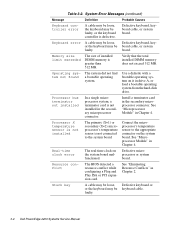
... board. Reseat the DIMMs or replace the system board. Memory controller or DIMM failure Defective DIMMs or system board. Gate A20 failure Defective system board. 3-2 Dell PowerEdge 2200 Systems Service Manual Unexpected interrupt Improperly seated expansion card or the system needs rebooting.
... board. Reseat the DIMMs or replace the system board. Memory controller or DIMM failure Defective DIMMs or system board. Gate A20 failure Defective system board. 3-2 Dell PowerEdge 2200 Systems Service Manual Unexpected interrupt Improperly seated expansion card or the system needs rebooting.
Service Manual
Page 40
... a single microprocessor system, a terminator card is defective. Stuck key A cable may be loose, Defective keyboard or or the keyboard may be keyboard cable. faulty. 3-4 Dell PowerEdge 2200 Systems Service Manual Table 3-2. or the keyboard may be board cable, or system faulty. Processor X temperature sensor is not installed The primary (X=1) or secondary (X=2) microprocessor's temperature sensor is...
... a single microprocessor system, a terminator card is defective. Stuck key A cable may be loose, Defective keyboard or or the keyboard may be keyboard cable. faulty. 3-4 Dell PowerEdge 2200 Systems Service Manual Table 3-2. or the keyboard may be board cable, or system faulty. Processor X temperature sensor is not installed The primary (X=1) or secondary (X=2) microprocessor's temperature sensor is...
Service Manual
Page 44
... static charge from your personal safety and to prevent damage to the computer system from their power sources to reduce the potential for your body. 4-2 Dell PowerEdge 2200 Systems Service Manual Disconnect the computer and any of the computer chassis to discharge any communications cables. 4. If a wrist grounding strap is not available, touch any unpainted...
... static charge from your personal safety and to prevent damage to the computer system from their power sources to reduce the potential for your body. 4-2 Dell PowerEdge 2200 Systems Service Manual Disconnect the computer and any of the computer chassis to discharge any communications cables. 4. If a wrist grounding strap is not available, touch any unpainted...

Service Manual
Page 46
... bezel to keep the opening between the front bezel and the computer chassis equal on all sides to prevent damage to the bezel alignment pins. 4-4 Dell PowerEdge 2200 Systems Service Manual then grasp the front of the cover, and lift the cover straight up off the chassis (Figure 4-1). Pry the front bezel loose with your...
... bezel to keep the opening between the front bezel and the computer chassis equal on all sides to prevent damage to the bezel alignment pins. 4-4 Dell PowerEdge 2200 Systems Service Manual then grasp the front of the cover, and lift the cover straight up off the chassis (Figure 4-1). Pry the front bezel loose with your...
Service Manual
Page 48
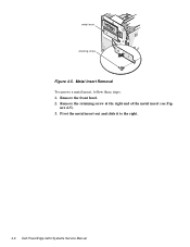
Metal Insert Removal To remove a metal insert, follow these steps: 1. Remove the retaining screw at the right end of the metal insert (see Fig- ure 4-5). 3. Pivot the metal insert out and slide it to the right. 4-6 Dell PowerEdge 2200 Systems Service Manual metal insert retaining screw Figure 4-5. Remove the front bezel. 2.
Metal Insert Removal To remove a metal insert, follow these steps: 1. Remove the retaining screw at the right end of the metal insert (see Fig- ure 4-5). 3. Pivot the metal insert out and slide it to the right. 4-6 Dell PowerEdge 2200 Systems Service Manual metal insert retaining screw Figure 4-5. Remove the front bezel. 2.
Service Manual
Page 50
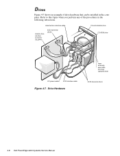
Refer to this figure when you perform any of drive hardware that can be installed in the following subsections. Drive Hardware lower externally accessible drive bay (optional drive) SCSI hard-disk drives 4-8 Dell PowerEdge 2200 Systems Service Manual Drives Figure 4-7 shows an example of the procedures in the computer. diskette drive interface cable diskette drive interface connector (FLOPPY) SCSI connector (SCSI) 3.5-inch diskette drive CD-ROM drive DC power cables SCSI interface cable Figure 4-7.
Refer to this figure when you perform any of drive hardware that can be installed in the following subsections. Drive Hardware lower externally accessible drive bay (optional drive) SCSI hard-disk drives 4-8 Dell PowerEdge 2200 Systems Service Manual Drives Figure 4-7 shows an example of the procedures in the computer. diskette drive interface cable diskette drive interface connector (FLOPPY) SCSI connector (SCSI) 3.5-inch diskette drive CD-ROM drive DC power cables SCSI interface cable Figure 4-7.

Service Manual
Page 52
... bus termination jumpers to 68-pin adapter drive-mounting extensions drive-release tabs Figure 4-9. drive-mounting rails (2) 50-pin to the settings you recorded. 4-10 Dell PowerEdge 2200 Systems Service Manual Check the back of the drive. If present, remove the 50-pin to 68-pin adapter between the SCSI cable and the drive connector.
... bus termination jumpers to 68-pin adapter drive-mounting extensions drive-release tabs Figure 4-9. drive-mounting rails (2) 50-pin to the settings you recorded. 4-10 Dell PowerEdge 2200 Systems Service Manual Check the back of the drive. If present, remove the 50-pin to 68-pin adapter between the SCSI cable and the drive connector.


